Practical industrial safety, risk assessment and shutdown systems, elsevier (2003)
Bạn đang xem bản rút gọn của tài liệu. Xem và tải ngay bản đầy đủ của tài liệu tại đây (29.21 MB, 359 trang )
Practical Industrial Safety, Risk Assessment, and
Shutdown Systems by Dave Macdonald
• ISBN: 0750658045
• Publisher: Elsevier Science & Technology Books
• Pub. Date: January 2004
Preface
Most of today's computer controlled industrial processes involve large amounts of energy and have the
potential for devastating accidents. Reliable, well-engineered safety systems are essential for
protection against destruction and loss of life.
This book is an intensive practical and valuable exposure to the most vital, up-to-date information
and practical know-how to enable you to participate in hazard studies and specify, design, install and
operate the safety and emergency shutdown systems in your plant, using international safety practices.
This book will provide you with a broad understanding of the latest safety instrumentation practices
and their applications to functional safety in manufacturing and process industries. This book could
save your business a fortune in possible downtime and financial loss.
The objectives of the book are to:
• Expand your practical knowledge in the application of safety instrumented
systems (SIS) as applied to industrial processes
• Provide you with the knowledge of the latest standards dealing with each stage of
the safety life cycle fi*om the initial evaluation of hazards to the detailed
engineering and maintenance of safety instrumented systems
• Give you the ability to plan hazard and risk assessment studies, then design,
implement and maintain the safety systems to ensure high reliability
• Assist your company to implement functional safety measures to international
standards
There are least six practical exercises to give you the hands-on experience you will need to
implement and support hazard studies; perform reliability evaluations; specify requirements; design,
plan and install reliable safety and emergency shutdown systems in your business.
Although a basic understanding of electrical engineering principles is essential, even those with a
superficial knowledge will substantially benefit by reading this book.
In particular, if you work in any of the following areas, you will benefit fi-om reading this book:
• histrumentation and control engineers and technicians
• Design, installation and maintenance engineers and technicians in the process
industries
• Managers and sales professionals employed by end users
• Systems integrators
• Systems consultants
• Consulting electrical engineers
• Plant engineers and instrument technicians
• Operations technicians
• Electrical maintenance technicians and supervisors
• histrumentation and control system engineers
• Process control engineers
• Mechanical engineers
Preface xvii
The structure of the book is as follows.
Chapter 1: Introduction, A review of the fundamentals
in safety instrumentation focussing
on a discussion on hazards and risks, safety systems engineering, and introduction to the lEC 61508
and ISA S84 standards. A concluding review of the safety life cycle model and its phases.
C h a p t e r 2 : H a z a r d s a n d risk r e d u c t i o n . An examination of basic hazards, the chemical
process, hazards studies, the lEC model, protection layers, risk reduction and classification and the
important concept of the safety integrity level (SIL).
Chapter 3: Hazard studies. A review of the outline of methodologies for hazard studies 1,
2 and 3.
Chapter 4: Safety requirements specifications. A discussion and guide to preparing
a safety requirements specification (SRS).
Chapter 5: Technology choices and the conceptual design stage. An
examination of how to get the concepts right for the specific application and choosing the right type of
equipment for the job, not the particular vendor but at least the right architecture for the logic solver
system and the right arrangement of sensors and actuators to give the quality of system required by the
SRS.
Chapter 6: Basic reliability analysis applied to safety systems. This discusses
the task of measuring or evaluating the SIS design for its overall safety integrity.
Chapter 7: Safety in field instruments and devices. This chapter examines the
range of instrumentation design techniques that have accumulated in the industry through experience
that began a long time before the days of PES and the high performance logic solvers.
Chapter 8: Engineering the safety system: hardware. An examination of two
aspects of engineering work for building an SIS. Firstly there is a look at some aspects of project
engineering management and secondly some basic engineering practices.
Chapter 9: Engineering the application software. Guidance is provided here on
how to deal with the application software stages of an SIS project with an examination of some of the
basic concepts and requirements that have been introduced in recent years to try to overcome the
major concerns that have arisen over the use of software in safety applications.
Chapter 10: Overall planning: lEC Phases 6,7 and 8. A brief look at the
planning boxes marked in on the lEC safety life cycle.
Chapter 1 1 : Installation and commissioning (lEC phase 12). TWS chapter
tracks the safety system from its building stage through factory acceptance testing, delivery and
installation and into final testing for handover to the operating team.
xvlii Preface
Chapter 12: Validation, operations and management of change (IEC
p h a s e s 1 3 , 1 4 a n d 1 5 ) . A discussion on validation, operations and maintenance.
Chapter 13: Justification for a safety instrumented system, in practice
engineers and managers have to make choices on the type, quaUty, and costs of the safety solutions
available within the constraints imposed by the essential safety requirements. This is discussed in
detail in this chapter.
Table of Contents
Preface
1
Introduction
2
Hazards and risk reduction
33
3
Hazard studies
65
4
Safety requirements specifications
108
5
Technology choices and the conceptual design stage
135
6
Basic reliability analysis applied to safety systems
171
7
Safety in field instruments and devices
200
8
Engineering the safety system: hardware
230
9
Engineering the application software
244
10
Overall planning: IEC phases 6, 7 and 8
255
11
Installation and commissioning (IEC phase 12)
264
12
13
Validation, operations and management of change (IEC phases
13, 14 and 15)
1
279
Justification for a safety instrumented system
296
App. A: Practical exercises
306
App. B: Glossary
343
Index
349
Introduction
1.1
Definition of safety instrumentation
What is safety instrumentation?
Here is a typical definition.
(Origin: UK Health and Safety Executive: 'Out of Control')
'Safety instrumented systems are designed to respond to conditions of a plant that may be
hazardous in themselves or if no action were taken could eventually give rise to a hazard.
They must generate the correct outputs to prevent the hazard or mitigate the
consequences'
Abbreviation: The acronym SIS means ^safety instrumented system'. We probably
all know the subject by other names because of the different ways in which these systems
have been applied. Here are some of the other names in use:
•
•
•
•
•
Trip and alarm system
Emergency shutdown system
Safety shutdown system
Safety interlock system
Safety related system (more general term for any system that maintains a safe
state for EUC)
Fig 1.1 defines the SIS as bounded by sensors, logic solver and actuators with associated
interfaces to users and the basic process control system. We are talking about automatic
control systems or devices that will protect persons, plant equipment or the environment
against harm that may arise from specified hazardous conditions.
2 Practical Industrial Safety, Risk Assessment and Shutdown Systems for Industry
Basic Process
Control System
SIS User
Interface
Sensors
Logic
Solver
Actuators
Figure 1.1
Definition of a safety instrumented system
We are talking about automatic control systems or devices that will protect persons,
plant equipment or the environment against harm that may arise from specified hazardous
conditions.
1.2
What is this book about?
This book is about instrumentation and control systems to support:
• The safety of people in their workplaces
• Protecting the environment against damage from industrial accidents
• Protecting businesses against serious losses from damage to plant and
machinery
• Creating awareness of the good practices available for the delivery of
effective safety instrumented systems
• Providing basic training in well established techniques for engineering of
safety systems
• Assisting engineers and technicians to support and participate in the safety
systems activities at their work with a good background knowledge of the
subject
• Being aware of what can go wrong and how to avoid it
1.3
Why is this book necessary?
• Safety systems are reaching wider fields of application
• Safety requires a multidiscipline approach
• New standards and new practices have emerged
There have been some steadily developing trends in the last 10 years which have moved
the subject of so-called functional safety from a specialized domain of a few engineers
into the broader engineering and manufacturing fields.
Basically, there is a need for a book to allow engineers and technicians to be aware of
what is established practice in the safety instrumentation field without having to become
specialists. After all it is the technicians who have to service and maintain the safety
systems and they are entitled to know about the best available practices.
Introduction 3
This book is also intended to be useful for:
• Project engineers and designers who may be involved in completely new
projects or in the modification/upgrading of existing plants
• Engineers involved in the development of packaged processing plants or
major equipment items where automatic protection systems may be needed
• Engineers and technicians working for instrumentation and control system
suppliers
1.4
Contents of the book
The subjects in this book cover the 'life cycle' of safety protection from the initial studies
and requirements stages through to the operation and support of the finished systems, i.e.
•
•
•
•
Identification of hazards and specification of the protection requirements
Technology choices
Engineering of the protection systems
Operations and maintenance including control of changes
This subject is well supplied with specialized terms and abbreviations, which can be
daunting and confusing. We have attempted to capture as many as possible in a glossary.
This is located at the back of the book.
Reference book: Acknowledgments are given to the authors of the following book for
many helpful features in their book that have been of assistance in the preparation of this
particular book. Details of this book are as follows:
Title: Safety Shutdown Systems: Design, Analysis and Justification
By: Paul Gruhn and Harry Cheddie
Published by: Instrument Society of America, 1998. ISBN 1-5517-665-1
Available from ISA Bookstore website: www.isa.org
1.5
Introduction to hazards and risks
The first part of the book is all about the identification of hazards and the reduction of the
risks they present.
What is a hazard and what is a risk?
A hazard is 'an inherent physical or chemical characteristic that has the potential for
causing harm to people, property, or the environment'
In chemical processes: 'It is the combination of a hazardous material, an operating
environment, and certain unplanned events that could result in an accident.'
Risk: 'Risk is usually defined as the combination of the severity and probability of an
event. In other words, how often can it happen and how bad is it when it does? Risk can
be evaluated qualitatively or quantitatively'
Roughly: RISK = FREQUENCY x CONSEQUENCE OF HAZARD
Consider the risk on a cricket field.
4 Practical Industrial Safety, Risk Assessment and Shutdown Systems for Industry
If we can't take away the hazard we shall have to reduce the risk
Reduce the frequency and/or reduce the consequence
I Example:
Glen McGrath is the bowler: He is the Hazard
{ You are the batsman: You are at risk
Frequency = 6 times per over. Consequence = bruises!
Risk = 6 X briiisesl
Risk reduction: Limit bouncers to 2 per over. Wear more pads.
Risk -^ 2 ^ siiial! bruise!
L^,..
Figure 1.2
Risk reduction: the fast bowler
1.5.1
Risk reduction
The reduction of risk is the job of protection measures. In some cases this will be an
alternative way of doing things or it can be a protection system such as a safety
instrumented system. When we set out designing a protection system we have to decide
how good it must be. We need to decide how much risk reduction we need (and this can
be one of the hardest things to agree on). The target is to reduce the risk from the
unacceptable to at least the tolerable. This principle has a fundamental impact on the way
we have to design a safety system as shown in the following diagram.
Hazard Identified
I
Risk
^dfcs
Estimatedtalculated
Tolerable Risk
Established
Risk Reduction
I
Safety Function
Defined
Figure 1.3
Risk reduction: design principles
The concept of tolerable risk is illustrated by the following diagram showing what is
known as the principle of ALARP.
Introduction 5
ALARP boundaries for individual risks: Typical values.
Risk magnitude
Intolerable region
Typically fatality risk is higher
than 10 £-4
The ALARP or
tolerability region
Risk cannot be justified
except in extraordinary
circumstances
Tolerable only if further risk reduction
is impracticable or if its cost is grossly
iisproportionate to the improvement gained
(risk is undertaken
only if a benefit is desired)
Tolerable if cost of reduction would
exceed the improvements gained
Broadly acceptable region
Typically fatality risk is lower
than 10 E-6
It is necessary to maintain
assurance that risk remains at
this level
Figure 1.4
Principle of ALARP
The ALARP (as low as reasonably practicable) principle recognizes that there are three
broad categories of risks:
• Negligible Risk: broadly accepted by most people as they go about their
everyday lives, these would include the risk of being struck by lightning or of
having brake failure in a car.
• Tolerable risk: We would rather not have the risk but it is tolerable in view of
the benefits obtained by accepting it. The cost in inconvenience or in money is
balanced against the scale of risk and a compromise is accepted. This would
apply to traveling in a car, we accept that accidents happen but we do our best
to minimize our chances of disaster. Does it apply to Bungee jumping?
• Unacceptable risk: The risk level is so high that we are not prepared to
tolerate it. The losses far outweigh any possible benefits in the situation.
Essentially this principle guides the hazard analysis participants into setting tolerable
risk targets for a hazardous situation. This is the first step in setting up a standard of
performance for any safety system.
1.6
Fatal accident rate (FAR)
This is one method of setting a tolerable risk level. If a design team is prepared to define
what is considered to be a target fatal accident rate for a particular situation it becomes
possible to define a numerical value for the tolerable risk. Whilst it seems a bit brutal to
set such targets the reality is that certain industries have historical norms and also have
targets for improving those statistical results.
6 Practical Industrial Safety, Risk Assessment and Shutdown Systems for Industry
The generally accepted basis for quoting FAR figures is the number of fatalities per one
g
hundred million hours of exposure. This may be taken as the fatalities per 10 worked
hours at a site or in an activity but if the exposure is limited to less than all the time at
work this must be taken into account.
Very roughly 1 person working for 50 years or 50 people working for 1 year will
accumulate 10 working hours
If 50 000 people are employed in the chemical industries there will be an average of:
8
50 000 X 2000 hrs worked per year = 1 x 1 0 hrs worked per year. If the same industry
recorded an FAR of 4 it means an average of 4 fatalities per year has occurred.
You can see from the following table that this scale of measurement allows some
comparisons to be made between various activities. Another scale of measurement is the
probability of a fatal accident per person per year for a particular activity.
Activity
FAR per 10*
Travel
Air
Train
Bus
Car
Occupation
Chemical industry
Manufacturing
Shipping
Coal mining
Agriculture
Boxing
Rock climbing
Staying at home
Living at 75 (based on simple
calculation of hr/lifetime)
3-5
4
50-60
4
8
8
10
10
20 000
4 000
1^
152
Individual risk of
deatli per person per
year x lO"^
0.02
0.03
2
2
0.5
9
2
1.4
133
Table 1.1
Individual risk andfatal accident rates based on UK data
FAR can be used as basis for setting the tolerable rate of occurrence for a hazardous
event. For example:
Suppose a plant has an average of 5 persons on site at all times and suppose that 1
explosion event is likely to cause 1 person to be killed. The site FAR has been set at 2.0 x
10"^/hr. We can calculate the minimum average period between explosions that could be
regarded as tolerable, as follows:
Fatality rate per year = (FAR/hr) x (hours exposed/yr)
=
=
(2 X 10"^) X (5 X 8760)
8.76 X 10"^
Avg. years per explosion = 1/8.76 x 10"^ = 1140 year
Introduction 7
Note: If there are A^ separate sources of explosion of the same type the period for each
source will be: A^ x 1140 years. These figures will define the target risk frequencies for
determining the scale of risk reduction needed fi-om a safety system.
1.7
Overview of safety systems engineering (SSE)
The term safety systems engineering is used to describe the systematic approach to the
design and management of safety instrumented systems.
1.7.1
Introduction
Safety systems engineering (SSE) comprises all the activities associated with the
specification and design of systems to perform safety functions. SSE has become a
discipline within the general field of engineering. Whenever there is a clear and obvious
need for safety to be engineered into any activity it should be done properly and in a
systematic manner.
1.7.2
What do we mean by safety functions?
We mean any function that specifically provides safety in any situation. E.g. a seat belt in
a car, an air bag, a pressure relief valve on a boiler or an instrumented shutdown system.
Thus an air bag has a safety function to prevent injury in the event of collision. The safety
system of an air bag comprises the sensor, the release mechanism, the inflator and the bag
itself
1.7.3
Functional safety
The term 'functional safety' is a concept directed at the functioning of the safety device
or safety system itself It describes the aspect of safety that is associated with the
functioning of any device or system that is intended to provide safety. The best
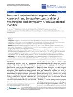
description might be this one from the following journal article:
'Functional safety in the field of industrial automation' by Hartmut von Krosigk.
Computing and Control Engineering Journal (UK lEE) Feb 2000.
'In order to achieve functional safety of a machine or a plant the safety related
protective or control system must function correctly and, when a failure occurs, must
behave in a defined manner so that the plant or machine remains in safe state or is
brought into a safe state.'
Short form: 'Functional safety is that part of the overall safety of a plant that depends
on the correct functioning of its safety related systems.'
(Modified from lEC 61508 part 4.)
The next diagram shows how functional safety makes a contribution to overall safety.
8 Practical Industrial Safety, Risk Assessment and Shutdown Systems for Industry
Overall Safety is seen as part of overall safety
Protection against
dangerous
radiation
-•wmcmmm' •
Protection against
electric sliocic
dM to ftuit^ml wroini
Protection against
lieat and fire
f
Protection against
mechanical liazards
and moving objects
Figure 1.5
Overall safety
The well-known standards certification authority in Germany is TUV. Their website
answers the question ' What is functional safety?'
Random hardware faults or systematic design errors - e.g. in software - or human
mistakes shall not result in a malfiinction of a safety related unit/system with the potential
consequence of:
• Injury or death of humans or
• Hazards to the environment or
• Loss of equipment or production
Then follows an explanation of the term 'unit/system'; for example:
• A simple device as a gas burner control unit
• A large distributed computer system like emergency shutdown and
fire & gas systems
• A field instrument
• The complete instrumented protective equipment of a plant
So we can conclude that functional safety is about the correct fiinctioning of a unit or
system designed to protect people and equipment from hazards.
1.8
Why be systematic?
Why be so formal? Why be systematic?
Critics might say...
•
•
•
•
We don't need all these rules!
Why not just use common sense?
Whose job is it anyway?
Make the contractor do it!
But now let's take a look at the problem.
Introduction 9
15H
6%
Bm04^S4im0m^^aMmmefm$inTh0
iM:
'*amafCimimr\MM:
Figure 1.6
Causes of control system failures
Specification errors dominate the causes of accidents analyzed in the above survey.
1.8.1
UKHSE publication
One of the best advocates for a systematic approach to safety engineering is the UK
Health and Safety Executive (HSE): Their publication: 'Out ofContror is a very useful
little book about' Why control systems go wrong and how to prevent failure' and it is the
origin of the analysis we have just seen.
This book not only provides extracts from the analyses of accidents but also explains
with great clarity the need for a systematic approach to the engineering of functional
safety. It also provides a valuable outline of the safety life cycle.
1.8.2
HSE summary
Some of the key points from the study are listed below:
Analysis of incidents
• Majority of incidents could have been anticipated if a systematic risk-based
approach had been used throughout the life of the system
• Safety principles are independent of the technology
• Situations often missed through lack of systematic approach
Design problems
•
•
•
•
Need to verify that the specification has been met
Over dependence on single channel of safety
Failure to verify software
Poor consideration of human factors
10 Practical Industrial Safety, Risk Assessment and Shutdown Systems for Industry
Operational problems
• Training of staff
• Safety analysis
• Management control of procedures
(An extract from the summary is given below).
' The analysis of the incidents shows that the majority were not caused by some subtle
failure mode of the control system, but by defects which could have been anticipated if a
systematic risk-based approach had been used throughout the life of the system. It is also
clear that despite differences in the underlying technology of control systems, the safety
principles needed to prevent failure remain the same.'
Specification
'The analysis shows that a significant percentage of the incidents can be attributed to
inadequacies in the specification of the control system. This may have been due either to
poor hazard analysis of the equipment under control, or to inadequate assessment of the
impact of failure modes of the control system on the specification. Whatever the cause,
situations which should have been identified are often missed because a systematic
approach had not been used. It is difficult to incorporate the changes required to deal
with the late identification of hazards after the design process has begun, and more
difficult, (and expensive), to make such changes later in the life of the control system. It is
preferable to expend resources eliminating a problem, than to expend resources in
dealing with its effects.'
Design
'Close attention to detail is essential in the design of all safety-related control systems,
whether they are simple hard-wired systems, or complex systems implemented by
software. It is important that safety analysis techniques are used to ensure that the
requirements in the specification are met, and that the foreseeable failure modes of the
control system do not compromise that specification. Issues of concern, which have been
identified, include an over-optimistic dependence on the safety integrity of single channel
systems, failure to adequately verify software, and poor consideration of human factors.
Good design can also eliminate, or at least reduce, the chance of error on the part of the
operator or maintenance technician.'
Maintenance and modification
' The safety integrity of a well designed system can be severely impaired by inadequate
operational procedures for carrying out the maintenance and modification of safetyrelated systems. Training of staff inadequate safety analysis, inadequate testing, and
inadequate management control of procedures were recurring themes of operational
failures.'
1.8.3
Conclusion: It pays to be systematic
Being systematic allows us to:
• Benefit from previously acquired knowledge and experience
• Minimize the chances of errors
Introduction 11
• Demonstrates to others that we have done the job properly... they recognize
our way of doing things as legitimate
• Makes it easier to compare one solution or problem with another and
hence leads to generally accepted standards of protection
• Allows continuity between individuals and between different participants in
any common venture - makes the safety system less dependent on any one
individual
• Encourages the development of safety products that can be used by many
• Support regulatory supervision and compliance
1.8.4
Scope 1 of safety systems engineering
The next diagram shows how safety system engineering covers the whole life of an
application. Quality assurance practices support the application at every stage.
Safety Systems Engineering
Hazard
Identification
Safety
Requirements
Specification
Design & Build
Safety System
Operate and
Maintain
Quality
Assurance
Figure 1.7
Scope of safety systems engineering
1.9
Introduction to standards: lEC 61508 and ISA S84
Up until the 1980s the management of safety in hazardous processes was left to the
individual companies within the process industries. Responsible companies evolved
sensible guidelines out of the knowledge that if they didn't take care of the problem they
would be the nearest people to the explosion when it happened. The chemical industry for
example was always aware that self-regulation would be better than rules imposed by a
worried public through government action.
More recently, industry guidelines have matured into international standards and
government regulators are seeing the potential benefits of asking companies and products
to conform to what are becoming generally agreed standards. It's ironic that the better the
standard the easier it becomes to enforce laws requiring conformance to that standard.
Here we take a look at how we have arrived at the point where new international
standards are available. Then we look at the main standards to be used in this book.
1.9.1
Driving forces for management of safety
There are many reasons for wanting to improve the management of safety.
12 Practical Industrial Safety, Risk Assessment and Shutdown Systems for Industry
•
•
•
•
•
•
•
•
•
•
•
1.9.2
We (the public) want to know that safety is properly organized
Cost of accidents, catastrophes
Rewards are high if the risk is low (Nuclear power)
SHE Responsibilities of companies, designers and operators
Legal requirements
Complexities of processes and plants
Hazards of multiple ownership
Falling through the cracks. (Railways)
Liabilities of owners, operators and designers
Insurance risks and certification
Programmable Electronic Systems (PES)
Evolution of functional safety standards
TUV(1984)
lEC 61508 98-2000
DIN V 19250 / VDE V 0801
i^it^ V i^^^ui vi-ri- v wuwi
(Germany)
^
- Risk classification 1989 ^ ^
- Safety system r e a u j r e m ^ ^ ^
" ? \ ^ ? " f^f
"^^ ^^^'^ ,
- Safety plan/management
_ Safety integrity levels
« Safety system diagnostic
requirements
- Safety system architectures
and reliability figures
^ ^ ^ ^ ^ ^ ^ ^ ^ ^
A ., .
^.
• Various n a t i o n a ^ ^ ^ ^ ^ ^ ^ ^ ^ ^
•
ANSI/ISA S84.0
- Safety procedures
- Safety life cycle
•
NFPA/UL1998
•
OSHA (29 CFR 1910.119)
•
UKHSE
Courtesy: Honeywell SMS
Figure 1.8
Evolution of functional safety standards
Programmable systems and network technologies have brought a new set of problems
to functional safety systems. Software comes with new possibilities for performance
failure due to program errors or untested combinations of coded instructions. Hence
conventional precautions against defects in electrical hardware will not be sufficient to
ensure reliability of a safety system.
Earlier design standards did not provide for such possibilities and hence they became
obsolete.
Newer standards such as the German VDE 0801 and DIN 19250 emerged in the late
1980s to incorporate quality assurance grading for both hardware and software matched
to the class of risk being handled. Li the USA the ISA S84.01 standard was issued in 1995
for use in process industry applications including programmable systems. In the UK the
Introduction 13
HSE promoted the drive for an international standard. These and many other factors have
resulted in the issue of a new general standard for functional safety using electronic and
programmable electronic equipment. The new standard issued by the lEC is lEC 61508
and it covers a wide range of activities and equipment associated with functional safety.
The newer standards bring a new approach to the management and design of functional
safety systems. They try to avoid being prescriptive and specific because experience has
shown that: 'A cookbook of preplanned solutions does not work.'
The new approach is to set down a framework of good practices and limitations leaving
the designers room to find appropriate solutions to individual applications.
1.9.3
Introducing standard lEC 61508
International Electrotechnical Commission
Title:
Functional safety of electrical/electronic/programmable
electronic safety-related systems All Sections of lEC 61508 Now Published
Part 1: Generai requirements
Part 2: Requirements for electrical/electronic/programmable
electronic systems
Part 3: Software requirements
Part 4: Definitions and abbreviations
Part 5: Examples of methods for the determination of safety
integrity levels
Part 6: Guidelines on the application of parts 2, 3
Part 7: Overview of techniques and measures
See Appendix 1 for Framework Diagram
Figure 1.9
Standard lEC 61508
This diagram shows the title of the standard and its 7 parts issued to date. An additional
part 8 is in preparation, which will provide a further set of guidelines for the application
of the standard.
1.9.4
Key elements of lEC 61508
•
•
•
•
1.9.5
Management of functional safety
Technical safety requirements
Documentation
Competence of persons
Features of lEC 61508
• Applies to safety systems using Electrical/Electronic/Programmable
Electronic Systems (abbreviation: E/E/PES) e.g. Relays, PLCs, Instruments,
Networks
• Considers all phases of the safety life cycle including software life cycle
• Designed to cater for rapidly developing technology
• Sets out a 'generic approach' for safety life cycle activities for E/E/PES
14 Practical Industrial Safety, Risk Assessment and Shutdown Systems for Industry
• Objective to 'facilitate the development of application sector standards'
• lEC 61511: process industry sector standard on the way
The standard is 'generic', i.e. it provides a generalized approach to the management and
design of functional safety systems that can be applicable to any type of industry. It is
intended for direct use in any project but it is also intended to be the basis for 'industry
sector' standards. Hence, more specific industry sector standards will be expected to
follow with alignment of their principles to the 'master standard'.
The lEC standard sets out procedures for managing and implementing a safety life
cycle (abbr: SLC) of activities in support of a functional safety system. Hence, we can
map the various parts of the standard on to our previous diagram of the safety life cycle as
shown in the next diagram.
1
Part 1: Documentation, Management of Functional Safety, F.S. Assessment
|
Part 7: Overview of techniques and measures
Part 1: Dev of overall safety requirements
Part 1: Allocation of
safety reqs. to the
E/E/PE safety-related
systems
Part 4:
Definitions
\
Parti: Install and 1
Commission
Part 2: Realization Phase
for systems
Part 1: Operate
and maintain
Part 3: Realization Phase
for software
Part 5: Risk based SILs
Hazard
Jt
Identification j ^ - ^
Part 6: Guidelines for
HW and SW
Design & Build
Safety System
Safety
|
Requirements ^
Specification
•
Back to re levant
ã4|MB K ằ a ô ô
""ã^
I
^
|
^
Operate and
Maintain
I
Modifications ^
The SLC spans all project phases and has return loops whenever modifications
Figure 1.10
Framework oflEC 61508 relevant to SLC
|
Introduction 15
1.9.6
Introducing Standard ANSI/S 84.01
Instrument Society of America
Title:
Application of Safety Instrumented Systems for the Process Industries
Sections of ISA S84.01
Clauses 1-11: Mandatory requirements
Clause 12:
Key differences from lEC 61508
Annexes A-E:Non mandatory (informative) technical information
Associated Document:
Draft Technical Report: 84.02 (ISA-dTR84.02)
Provides non mandatory technical guidance in Safety Integrity Levels
Figure 1.11
Standard ANSI/ISA S84.01 (USA) 1996
Features of ISA S84.01
• Applies to safety instrumented systems for the process industries
• Applies to safety systems using electrical/electronic/programmable electronic
systems (abbr: E/E/PES)
• Defines safety life cycle activities for E/E/PES but excludes hazard definition
steps associated with process engineering
• Objective: 'Intended for those who are involved with SIS in the areas of:
design and manufacture of SIS products, selection and application installation,
commissioning and pre-start-up acceptance test operation, maintenance,
documentation and testing'
The ISA standard is a much less ambitious standard than lEC 61508 and it confines
itself to the core instrument engineering activities relevant to process industries. It does
not attempt to deal with the hazard study and risk definition phases of the safety life
cycle.
1.9.7
Introducing Draft Standard lEC 61511
lEC 61511 is a process sector implementation of lEC 61508 and part 1 has been released
in 2003. The standard comprises three parts and includes extensive guidance on the
determination of target safety integrity levels that are to be set by the process design team
at the start of the design phase of a protection system.
lEC 61511: Functional Safety: Safety Instrumented Systems for the Process Industry
Sector
Part 1: Framework, definitions, system, hardware and software requirements
Part 2: Guidelines in the application of Part 1
Part 3: Guidance for the determination of safety integrity levels
16 Practical Industrial Safety, Risk Assessment and Shutdown Systems for Industry
lEC 61511 is directed at the end user who has the task of designing and operating an
SIS in a hazardous plant. It follows the requirements of lEC 61508 but modifies them to
suit the practical situation in a process plant. It does not cover design and manufacture of
products for use in safety, as these remain covered by lEC 61508.
Once lEC 61511 is released the process industries will be able to use it for end user
applications whilst devices such as safety certified PLCs will be built in compliance with
lEC 61508. lEC 61511 is expected to adopted in the USA and in the EU as the standard
for acceptable safety practices in the process industries. ISA S84 will then be superseded.
Relationships for Process lodiistr;^^ Safety System Standards
Proces»5 Sector
SaMySystraiStds
Manufacture
and Supply of Devices
lEC 61508
SIS Designers
Integrators & Users
lEC 61511
ISA S84.01
Figure 1.12
Relationship of present andfuture standards
This diagram shows how S84.01 is the precursor of a process industry sector version of
lEC 61508. It came out before the lEC standard but was designed to be compatible with
it. Eventually a new standard, lEC 61511, will fulfill the role and S84.01 will possibly be
superseded, for the present S84.01 is a very useful and practical standard with a lot of
engineering details clearly spelt out. Draft copies of parts of lEC 61511 are incorporating
many of the good features set out in ISA S84.01 whilst at the same time aligning its
requirements with lEC 61508.
1.10
Equipment under control
The term EUC or equipment under control is widely used in the lEC standard and has
become accepted as the basis for describing the process or machinery for which a
protection system may be required. The following diagram. Figure 1.13, based on a
diagram published in the HSE book 'Out of Control' illustrates what is meant by the term
'equipment under control', abbreviated: EUC.
Introduction 17
Scope of Equipment Under Control
Raw materials
energy status
I
Operator's
commands
instructions
Product movement
energy
EUC risk
includes EUC
control system
Operator display,
information
|
Figure 1.13
EUC
The definition of equipment under control given in the lEC standards is:
'Equipment, machinery, apparatus or plant used for manufacturing, process,
transportation, medical or other activities.' This includes the EUC control system and the
human activities associated with operating the EUC.
This terminology is significant because it makes it clear that the risks we have to
consider include those arising from a failure of the control system and any human
operating errors.
1.11
The safety life cycle model and its phases (SLC phases)
Introducing the safety life cycle
The foundation for all procedural guidelines in Safety Instrumented Systems is the Safety
Life Cycle (SLC).
The safety life cycle model is a useful tool in the development of safety related control
systems. Li concept it represents the interconnected stages from conception through
specification, manufacture, installation, commissioning, operation, maintenance,
modification and eventual de-commissioning of the plant.
It is visualized by a flow chart diagram showing the procedures suggested for the
management of the safety functions at each stage of the life cycle.
1.11.1
Basic SLC
There are a number of versions of the SLC and there is no reason why a particular design
team should not draw its own variations. However the standards we have been looking at
have drawn up their versions and have laid out their detailed requirements around the
framework provided by the SLC.
18 Practical Industrial Safety, Risk Assessment and Shutdown Systems for Industry
1.11.2
ISASLC
Notice how the activities outside of the ISA scope are shown in fainter outHnes. See also
references to applicable clauses in the text of the standard.
i
1r
Develop Safety
Requirements
Specification
Conceptual
Process Design
(4.2.1)
1
i
1
Perform SIS
Conceptual Design
& Very it Meets the
SRS (4.2.7)
Perform Process
Hazard Analysis
& Risk Assessment
(4.2.2)
i
^ Apply non-SiS "
Protection Layers to
Prevent Identified
Hazards or Reduce
Risk (4.2.3)
r
^'^^ Required
J>
i
Perform SIS
Detail Design
(4.2.8)
^
(y
(4.2.6)
r
i Establish Operation
& Maintenance
Procedures
\
(4.2.11)
(
\
Pre-Startup Safety
Review
(Assessment)
(4.2.12)
V
^
i
SIS Startup,
Operation,
Maintenance, Periodic
Functional Testing
(4.2.13)
i
SIS Installation ^
Commissioning and
Pre-Startup
Acceptance Test
(4 2.9 and 4.2.10)
^^''^iVtodify ^\,,^^ Modify
^ ^ v ^ S ? (4.2.14)^.x^
T Yes
1 Decom m i ssi on
r
Define Target SIL
(4.2.5)
J
-1
SIS
Decommissioning
(4.2.1.5)
Figure 1.14
ISA SLC
1.11.3
lEC SLC versions
Finally we need to look at the lEC version as this is the most general version and forms
the essential core of the lEC standard.
Introduction 19
Concept
Overall scope definition
y
Hazard and risk analysis
y
Overall safety requirements
Safety requirements allocation
i
Overall planning
| H H |
Safety related systems:
E/ePES
Safety related
systems: other
technologies
1Q
3
Realization (see E/BPES
safg^ llfecycie)
Overall
operation &
maintenance
planning
I
I
I
I
ã
H
ã
H
ZZ::L_Iô
Overall I ã
Overall
ã H T Overall Installation and
commissioning
validation I •
Installation and I | ^ H |
planning I H j commissioning I H H l .
I H
planning
I H B H I ^ Overall safety validation
,—I m
E==t^!^m
Overall operation and
maintenance and repair
i1
External risk
reduction facilities I
Realization
Realization
Back to appropriate
overall safety
life cycle phase
W
! ^
Overall modification
and retrofit
Decommissioning or
disposal
Figure 1.15
lEC SLC version
The lEC SLC indicates the same basic model that we have been considering but adds
very specific detail phases as numbered boxes. Each box is d reference to a detailed set of
clauses defining the requirements of the standard for that activity. The boxes are easy to
follow because they are defined in terms of:
• Scope
• Objectives
• Requirements
• Inputs from previous boxes
• Outputs to next boxes
Using the SLC assists participants in a safety project to navigate through the procedures
needed for the systematic approach we saw earlier
Note the stages of the lEC model. The first 4 phases are concerned with design, then the
'realization' phase is reached. This term describes in very general terms the job of
actually building the safety system and implementing any software that it contains.
Once the SIS has been built, the life cycle activities move on to 'installation,
commissioning, and validation'. Finally we get to use the safety system for real duties
and arrive at the operating and maintenance phase.
In the 'Out of Control' book the HSE provides a commentary on the method of working
with the safety life cycle. Like any project model the stages are basically in sequence 'the
deliverables of one stage provide the inputs to the next'. However, unlike a project plan
the safety life cycle must be regarded as a set of interconnected activities rather than a
20 Practical Industrial Safety, Risk Assessment and Shutdown Systems for Industry
simple top down design method. It is intended that iteration loops may be carried out at
any stage of work; it does not require the completion of one activity before starting
another: i.e., 'a concurrent design approach can be used'.
3
Hazard and risk analysis
4
>|r
Overall safety requirements
Safety requirements allocation
^The deliverables of one phase provide the input to the next'
Figure 1.16
Safety life cycle progression
This shows the idea of a continual iteration between life cycle activities and the
verification/assessment task. This is to maintain vigilance that a new activity is always
compatible with what has gone before. We might add that this presents a potential
nightmare for a project manager!
Large sections of lEC 61508 are concerned with the details of the realization phase and
there are whole life cycle models for the activities contained within this stage. Some
sections of the lEC standard are dedicated to these specialized tasks. Bear in mind that
some of the deeper parts of this standard will be applicable to manufacturers of certified
safety PLCs and their associated software packages. A process engineering project would
not be expected to dive into such depths.
1.12
Implications of lEC 61508 for control systems
1.12.1
Some Implications of lEC 61508 for control systems
1. This standard is the first international standard that sets out a complete management
procedure and design requirements for overall safety control systems. Hence it opens up
the way for conformance to be enforced by legislation.
2. Control systems and PLCs serving in safety related applications may be required in the
future to be in conformance with the requirements laid down in lEC 61508.
Conformance may be required by regulatory authorities before licenses are issued.
3. All forms of control systems with any potential safety implications could be subject to
evaluation or audit in terms of lEC 61508.
4. Design and hardware/software engineering of any safety related control system is to be
evaluated and matched to required SILs.
5. Integrates responsibility for delivering safety across engineering disciplines, e.g.
process engineer, instrument engineer, software engineer, maintenance manager and