New control strategy for variable speed wind turbine with DC DC converters
Bạn đang xem bản rút gọn của tài liệu. Xem và tải ngay bản đầy đủ của tài liệu tại đây (613.38 KB, 5 trang )
New Control Strategy for Variable Speed Wind
Turbine with DC-DC converters
Vladimir Lazarov
*
, Daniel Roye
†
, Dimitar Spirov
*
†
and Zahari Zarkov
*
*
Technical University-Sofia, Bulgaria, e-mail: , ,
†
G2ELab, INP Grenoble, Saint-Martin-d'Hères, France, e-mail:
Abstract— The paper studies the performance of variable
speed wind turbine (VSWT) configuration with non-
inverting buck-boost converter. The wind turbine systems
consist of permanent magnet synchronous generator
(PMSG) connected to diode rectifier, DC chopper and load.
New control strategy, based on the maximum power point
tracking (MPPT) and limited power point tracking (LPPT)
algorithms is used to improve the system operation. When
necessary to limit the power injected to the grid, due to
system operator demands, a control unit is implementing to
switch between two regimes of wind turbine operation: at
maximum power and at limited power. The MPP tracker is
simple perturb and observation (P&O) controller in
combination with two optimum wind turbines power/torque
versus speed characteristics. Two control loops: inner feed
forward current control loop and outer voltage control
closed loop are applied for the non-inverting buck-boost
converter. The performance of the dynamic models and the
control loops is tested under various wind conditions. The
simulation results are shown. The results prove the strategy
and models reliability.
Keywords—wind energy, converter control, modeling,
simulation.
I. I
NTRODUCTION
The permanent magnet synchronous generator (PMSG)
based variable speed wind turbines (VSWTs) is widely
used in the wind industry because of his advantages such
as compact size and weight, dense flux, etc. To operate in
VSWT system, this generator should be connected either
with controlled rectifier or diode rectifier. Thus, two
configurations are possible: full size back-to-back
configuration with two voltage source converters as
rectifier and inverter and DC capacitor and configuration
with DC-DC converter. The Boost converter is most used
DC chopper for such configuration, possessing important
advantages in islanding systems (micro hydro turbines) or
in hybrid operation systems [1]. However, the boost
converter has a major drawback limiting the range of the
voltages and respectively the generator speed. For the
present study, novel configuration with diode rectifier and
non-inverting buck-boost DC chopper is investigated. The
non-inverting buck-boost converter is interesting for his
ability to produce higher or lower DC voltage than the
source voltage [2]. This specific feature of the converter
may be very useful in the cases of high wind speeds and
when the network system operator demands less power to
be transferred into the grid [3]. Combined with
appropriate control strategy, the advantages of this
particular DC-DC converter can ensure the VSWT with
more flexibility and operation time. The proposed new
control strategy is combination of hybrid MPPT algorithm
[4] for the normal operation of the VSWT and Limited
Power Point Tracking (LPPT) logic algorithm for the limit
power operation and represent an electrical mode to limit
the aero dynamical power instead of using mechanical
pitch system. The advantages of the faster electrical
system response and his relatively simple control can
make the VSWT very attractive for standard networks
application, as well for smart grid systems.
DC DC
Wind
profile
Wind
turbine
Drive
train
PMSG
Diode
rectifier
Boost
converter
LOAD
P electSpeed Duty ratio
VSWT Aero dynamical / Mechanical unit
MPPT
LPPT
Operator
Controller
speed
d
Control
strategy
VSWT Control unit
VSWT Electrical unit
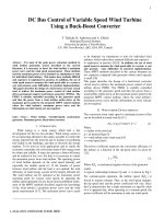
Fig. 1. Control concept of VSWT with non-inverting buck-boost DC-DC converter.
14th International Power Electronics and Motion Control Conference, EPE-PEMC 2010
978-1-4244-7855-2/10/$26.00 ©2010 IEEE T12-120
II. S
YSTEM
M
ODELING
The considered configuration is presented in Fig. 1. In
order to investigate the different modes of operations,
every element of the conversion system is modelled and
simulations are performed. The models are developed in
the MATLAB/Simulink
®
software environment.
A. Wind turbine model
The wind turbine extracts the wind aero dynamical
power. The model of the wind turbine uses several inputs
to estimate precisely the mechanical torque and power,
such as: the wind speed, the blade pitch angle and the
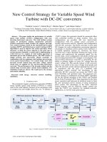
rotor speed. The wind speed is provided by a wind model.
Detailed wind models for complex aero dynamical
calculation can be found in [5]and [6]. For the electrical
simulations in this study, simplifying model is used.
Typical wind profile is shown on Fig. 2.
0 10 20 30 40 50 60 70 80 90 100
5
10
15
20
Time [s]
Wind speed [m/ s]
Fig. 2. Typical wind profile.
The aero dynamical power is described by (1)
()
θλνρ= ,
2
1
3
pwind
CAP (1)
Where ρ is the air density equal to 1.225 kg/m
3
, A is the
turbine blade surface, v is the wind speed and C
p
is turbine
power coefficient which depends on the tip speed ratio (2)
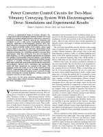
and θ is the pitch angle. The power coefficient is different
for every particular turbine and a convenient way to
reproduce the power curve is found in [7], using (2) and
(3).
i
a
i
p
eaa
a
aC
λ
−
⎟
⎟
⎠
⎞
⎜
⎜
⎝
⎛
−θ−
λ
=
5
43
2
1
(2)
⎟
⎟
⎠
⎞
⎜
⎜
⎝
⎛
+θ
−
θ+λ
=λ
1
1
3
2
1
b
b
i
(3)
The coefficients a
i
and b
i
are chosen to fit very small
power wind turbine (approximately 2 kW). The pitch
angle is θ and λ is the tip speed ratio (TSR). The power
coefficient of the turbine is shown in Fig. 3.
Fig. 3. Power coefficient curves for 2kW wind turbine model.
The turbine rotor swing is described by a standard one-
mass model.
B.
PMSG and diode rectifier models
The models of the generator and the diode rectifier
(DR) are developed using the SimPowerSystem® library
in the Matlab/Simulink®. The DR is universal bridge 3
arms diode rectifier.
C.
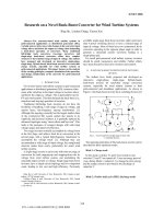
Non-inverting buck-boost converter model
The non-inverting buck-boost converter has two
switches, driven synchronously by PWM modulator as it
is shown in Fig. 4.
Fig. 4. Non-inverting buck-boost converter.
This model is similar to the model of the buck-boost
converter, but the output voltage polarity is not inverted.
The voltage ratio is defined as:
()
uu
V
V
DCin
DCout
−−= 1 (4)
Where V
DCin
is the supply voltage, V
DCout
is the output
voltage and u is the duty cycle ratio. The state-space
equation of the converter (5) can be used in average
Simulink models.
DCin
V
L
u
x
x
CC
u
L
u
x
x
⎥
⎥
⎦
⎤
⎢
⎢
⎣
⎡
+
⎥
⎦
⎤
⎢
⎣
⎡
⎥
⎥
⎥
⎦
⎤
⎢
⎢
⎢
⎣
⎡
−
−
−
−
=
⎥
⎦
⎤
⎢
⎣
⎡
0
11
1
0
2
1
2
1
(5)
Depending on the control strategy, the converter is
driven in buck or in boost mode. The non-inverting buck-
boost converter model is implemented in the study
simulations using the electrical ports of Matlab
SimPowerSystems
®
library, reproducing the electrical
circuit in Fig. 4.
T12-121
D.
Converter control
The model of the converter control is based on linear PI
current regulator and pulse width modulator, generating
the drive signal. The regulator compares the current
trough the boost inductance signal with current reference
set point from the power point tracker and the error is
process to the PWM generator. The converter drive
diagram can be seen in Fig. 5.
Power point
tracker
Current
sense
PI PWM
i*
i
edu
Fig. 5. DC-DC converter controller.
III.
N
EW
P
OWER
C
ONTROL
S
TRATEGY
In order to extract the maximum power available at
various wind speeds, two different control algorithms are
normally applied to the VSWT: pitch angle control and
speed (torque) control.
The pitch control algorithm is used to change the pitch
angle and the blades turn out slightly of the wind stream
as so limiting the aero dynamical power in above rated
wind speeds. This control acts directly upon an additional
hydraulic system and is very important to protect the
blades from breaking.
The speed control algorithm serves to keep the
generator rotor speed in certain boundaries. As the wind
fluctuates, the rotor will accelerate or decelerate in order
to maintain that TSR, which give the maximum power
coefficient. The control governs the generator by power
converters electrical means. The grid synchronization is
also accomplished by the converters (not considered in
this work). As the foreseen power converter configuration
consists of passive diode rectifier and of DC-DC
converter, the speed control is achieved by the non-
inverting buck-boost converter.
The reference signal for the converter drive is derived
from the power point tracker. The tracker is ruled by new
control strategy. The strategy is focused on the possibility
to control the VSWT in the right-side of power coefficient
curve, only using the wind turbine generator and the
power converters, instead of the pitch mechanism. This
strategy is based on hybrid MPP tracker [8] with simple
perturb and observation (P&O) algorithm [9], limited
power point tracker, switch logic algorithm and
predefined power/torque versus speed wind turbine
characteristics. Two specific regime of operation are
distinguished: normal turbine operation and restricted
turbine operation. When the conditions are normal, i.e. all
produced electric power is authorised to be grid injected,
the control strategy rely on the MPPT algorithm to keep
the turbine converting the maximum available aero
dynamical power. When conditions change, i.e. the
network system operator enforces the turbine to limit the
power transferred to the grid below of the maximum
available, the switch logic algorithm enables the LPPT
algorithm. The algorithm keeps the turbine at one of the
limited power point curves, as it can be seen on Fig. 6,
depending on the restricted conditions.
0 1 2 3 4 5 6 7 8
0
2
4
6
8
10
12
14
16
18
x 10
5
Mechanical speed [rad/s]
Power [W]
6m/s
8m/s
10m/s
11m/s
12m/s
13m/s
14m/s
MPP curve
LPP curve at 90%
LPP curve at 80%
LPP curve at 70%
LPP curve at 50%
Region of LPPT control
Region of MPPT control
Power [W]
Fig. 6. Regions of MPP and LPP control.
T12-122
Over again, the switch logic algorithm recalls the
hybrid MPPT algorithm, when restricted conditions are
cancelled. Normally, the MPP tracker count on the P&O
algorithm to find the maximum point. The algorithm is
implemented and is shown in Fig. 7 and Fig. 8.
P(k); ω(k)
Inputs
ΔP = P(k) - P(k-1);
Δω = ω(k) - ω(k-1);
Discretization
Kt = Δω/ΔP;
|Δω*(k)| = |ΔP(k).Kt|
Initialization
If (Δω*(k-1) = = 0)
S = Sign [ΔP];
else
S = Sign [ΔP].Sign[Δω*(k-1)];
Δω*(k) = S.|ΔP(k).Kt|
If (|ΔP(k)| < = P band)
ω*(k) = ω*(k-1);
else
ω*(k) = ω*(k-1) + Δω*(k);
Update;
End;
ω*(k)
Computation
Output
Fig. 7. Perturb and observe (P&O) algorithm.
1/Z
1/Z
w
P
W*
Kt
Fig. 8. Simplified Simulink model of the P&O controller.
Nevertheless, when sudden large change in the wind
speed occurs, the MPP tracker use predefined turbine
characteristics of the MPPT curve as it shown in Fig. 9.
0
50
100
150
200
250
0 10203040506070
Speed (rad/s)
Torque (Nm)
MPP curve LPP curve at 70% LPP curve at 40%
Fig. 9. Predefined torque curves.
IV.
S
IMULATION
R
ESULTS
The simulations with models of the above mentioned
configuration in MATLAB/Simulink
®
were performed.
The non-inverting buck-boost converter is controlled in
boost mode, which is suitable for variable speed wind
turbine operation. The input and output converter voltages
are shown in Fig. 11, following lightly the changes of the
wind profile at Fig. 10. The inductor current and the
reference current show adequate convergence and fast
controller response in Fig. 12.
0.4 0.6 0.8 1 1.2 1.4 1.6 1.8 2
5.5
6
6.5
7
Time [s]
Wind speed [m/s]
Fig. 10. Wind speed.
0.4 0.6 0.8 1 1.2 1.4 1.6 1.8 2
480
500
520
540
560
580
600
620
640
660
Time [s]
DC voltage [V]
Non-in vert ing buc k-boost D C v olta ge
Diode rectifier D C voltage
Fig. 11. DC voltages at real wind conditions.
T12-123
0.4 0.6 0.8 1 1.2 1.4 1.6 1.8 2
1
1.2
1.4
1.6
1.8
2
2.2
2.4
2.6
2.8
3
Time [s]
Current [A]
Converter current
Reference current
Fig. 12. Reference and converter currents with MPPT control.
0.4 0.6 0.8 1 1.2 1.4 1.6 1.8 2
600
800
1000
1200
1400
1600
1800
2000
2200
Time [s]
Pow er [W]
P curve MAX
P curve DC converter with LPPT at 100%
P curve DC converter with LPPT at 70%
Restricted condition of 70%
Fig. 13. Maximum and converter power curve
with MPP and LPP tracking.
The converter power curve is close to the turbine
maximum power curve for about 10 m/s wind speed of the
modeled turbine, as it shown on Fig. 13(upper curves) and
the turbine convert almost all available power. The
converter power curve is below the imposed restricted
limit, in Fig. 13 (bottom curve), even thought the turbine
continues to operate and to transfer electric power to the
network.
V.
C
ONCLUSION
The simulation results display satisfying convergence
of the converter power curve with the turbine maximum
power curve and good performance of the LPP tracker.
The non-inverting buck-boost converter operates
satisfactorily with the new control strategy and the
combination of the non-inverting chopper and this new
controller seems to be promising. Nevertheless,
investigation in more complex voltage control strategy for
the non-inverting buck-boost chopper is foreseen to
improve the advantages of this type of converter in high
wind speed region and increased rotor speed. The
advantages of the LPP control strategy can be also applied
in hybrid systems and autonomous grids, along with non-
inverting buck-boost converter or other power converter
configuration as boost DC-DC converter.
A
CKNOWLEDGMENT
The authors would like to thank the Bulgarian National
Research Fund for the financial support (contract
EE 106/07) and the Technical University-Sofia for the
financial aid (contract 102ни225-1/2010)
R
EFERENCES
[1] V. Lazarov, Roye, D., Zarkov, Z., Spirov, D “Analysis of DC
converters for wind generators” Proceedings of the XVI
International Symposium on Electrical Apparatus and
Technologies SIELA, Bourgas, Bulgaria, June 2009.
[2] D. Spirov, V. Lazarov, D. Roye, Z. Zarkov, O. Mansouri,
"Modélisation des convertisseurs statique dc-dc pour des
applications dans les énergies renouvelables en utilisant
MATLAB/Simulink", EF 2009, Compiegne, France.
[3] M. Braun, G. Arnold, H. Laukamp “Plugging into the Zeitgeist:
Experiences of photovoltaic network integration in Germany”,
IEEE Power & Energy magazine, Vol.7, No.3, pp.63-76, 2009.
[4] V. Lazarov, D. Roye, D. Spirov, “Study of Variable Speed Wind
Turbine with Boost and Non-inverting Buck-Boost choppers and
Maximum Power control strategy”, Proceedings of the 6
th
Japanese-Mediterranean Workshop on Applied Electromagnetic
Engineering for Magnetic, Superconducting and Nano Materials,
Bucharest, July 2009.
[5] O. Wasynczuk, D. T. Man, J. P. Sullivan ‘Dynamic Behavior of a
Class of Wind Turbine Generators during Random Wind
Fluctuations’, IEEE Transactions on Power Apparatus and
Systems, No. 6 June 1981.
[6] Z. Lubosny ‘Wind Turbine Operation in Electric Power Systems’,
Springer 2003.
[7] S. Heier ‘Grid Integration of Wind Energy Conversion Systems’,
WILEY, 2006.
[8] C. Patsios, A. Chaniotis, A. Kladas, "A hybrid maximum power
point tracking system for grid-connected variable speed wind-
generators," IEEE Power Electronics Specialists Conference,
PESC, vol., no., pp.1749-1754, 15-19 June 2008.
[9] I. Schiemenz, M. Stiebler, "Control of a permanent magnet
synchronous generator used in a variable speed wind energy
system," IEEE Electric Machines and Drives Conference, 2001.
IEMDC 2001, vol., no., pp.872-877, 2001.
T12-124