Tài liệu hướng dẫn sử dụng Pro bằng Tiếng Anh khá hay
Bạn đang xem bản rút gọn của tài liệu. Xem và tải ngay bản đầy đủ của tài liệu tại đây (471.05 KB, 60 trang )
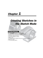
Chapter
1
Creating Sketches in
the Sketch Mode
After completing this chapter you will be able to:
• Use different SKETCHER options for creating a geometry.
• Dimension a sketch using the Normal option.
• Use the Mirror option in a sketch.
• Use the Intent Manager in a sketch.
• Modify a sketch.
• Use Modify Dimensions dialog box when you are using Intent Manager.
• Regenerate a sketch.
• Use drawing display options.
Learning Objectives
1-2 Pro/ENGINEER for Designers
© CADCIM Technologies, USA. For online training, contact
THE SKETCH MODE
Almost all the models designed in Pro/ENGINEER consists of datums, sketched features and
placed features. Generally, for creating datums and placed features, you do not require sketches.
However, to create a sketched feature, it is necessary to draw a two-dimensional (2D) sketch.
When you enter the Part mode and select the options to create any sketched feature, the
system automatically takes you to the sketcher environment. In the sketcher environment, the
sketch of the feature is created and regenerated, and then you return to the Part mode to
create the required feature. The sketches created in the Sketch mode are stored in .sec format.
You will learn about the datums and placed features in later chapters.
The Sketch mode is used when the design of a product is at its development stage. The designer
can sketch the 2D sketch of the product and assign required dimensions to it. By assigning the
dimensions, the designer can make sure that the 2D sketch of the product or model is satisfying
all the necessary conditions and then continue for the 3D model of the design, that is, the Part
mode.
Using the Sketch Mode
To create any section in the Sketch mode of Pro/ENGINEER, certain basic steps have to be
followed. The following steps outline the procedure to use the Sketch mode:
1. Sketch the required section geometry
The different sketcher tools available in this mode can be used to sketch the required section
geometry.
2. Add the constraints and dimension the sketched section
After sketching the section geometry, the constraints and dimensions are added to the section.
For dimensioning the section there are two options. Either the AutoDim option or the
DIMENSION submenu options available in the Menu Manager can be used. If the Intent
Manager is used for sketching then the sketch will be automatically dimensioned and
constrained. After adding the dimensions you can modify them as required.
3. Add relations to the sketch
The geometry of various entities of the sketch can be controlled by adding relations.
4. Regenerate the section
After dimensioning the sketch, the sketch must be regenerated. Remember that the section is
regenerated only if the minimum constraints of the sketch are satisfied. Pro/ENGINEER has
the capability to analyze the section and if the section is not complete for any reason, the
section will not be regenerated. However, Pro/ENGINEER makes certain assumptions to
regenerate the section.
If the Intent Manager is on while sketching then the sketch is automatically regenerated.
Entering the Sketch Mode
To enter the Sketch mode select New from the File menu or choose the Create a new object
Creating Sketches in the Sketch Mode 1-3
© CADCIM Technologies, USA. For engineering services, contact
button from the File toolbar. The New dialog box will be displayed with different
Pro/ENGINEER modes available. When you choose the Sketch radio button a default name of
sketch file appears in the Name edit box. You can change the sketch name as required. Choose
the OK button to enter the Sketch mode.
THE SKETCHER ENVIRONMENT
When you enter the Sketch mode, the initial screen appearance will be similar to the one
shown in Figure 1-1. This figure also shows the Sketcher Tools toolbar. The buttons available
in this toolbar are used to draw a sketch. When you enter the sketcher environment, by default
the Intent Manager is on. It is recommended to use the Intent Manager only if you are an
experienced user of this software. However, if you are a beginner, you should avoid using the
Intent Manager. In later chapters of this book, you will learn to create sketches using the
Intent Manager. You can turn off the Intent Manager by clearing the check mark on the left of
the Intent Manager option that is available in the Sketch menu in the menu bar.
Figure 1-1 Initial screen appearance after entering the Sketch mode
1-4 Pro/ENGINEER for Designers
© CADCIM Technologies, USA. For online training, contact
CREATING A SKETCH IN THE SKETCH MODE
If the Intent Manager is off, by default the Sketch option is
selected in the SKETCHER menu and the Mouse
Sketch option is selected in the GEOMETRY submenu. You
can start sketching either using the Intent Manager or without
using it. When you are drawing a sketch using the Intent
Manager, the Sketcher Tools toolbar is used. When you are
not using the Intent Manager to draw a sketch, the
Menu Manager is available with different sketcher options.
The options available under the GEOMETRY submenu are
shown in Figure 1-2. The section geometry can be sketched
using these options and their functions are discussed next.
Note
The sketch is saved as .sec file extension. While drawing in the Part mode if you save a drawing
before regenerating it, the part is saved in the .sec file extension.
In later chapters of this book you will create sketches using the Intent Manager. But, you should
learn to draw sketches without using the Intent Manager. This is because the basics of creating
sketches in Pro/ENGINEER are understood only when you draw sketches without using the
Intent Manager.
Drawing a Sketch Using the Mouse Sketch
Using the Mouse Sketch option you can create a desired section. You can draw lines, arcs that
start at the endpoint of any existing geometry, and circles by using the three button mouse.
The Mouse Sketch allows you to continuously draw a sketch without selecting the options
from the GEOMETRY submenu in the Menu Manager. For example, you can draw a line, a
circle, and an arc without selecting these options from the GEOMETRY submenu. The
equivalent of the Mouse Sketch option is not available when the Intent Manager is on. The
different entities that can be drawn using the Mouse Sketch option are discussed next.
Drawing a Line Using the Mouse Sketch
The following steps explain the procedure to sketch a line using the Mouse Sketch option:
1. Using the left mouse button, specify a point on the graphics screen from where you want
the line to start. A red rubber-band line appears, one end of which is fixed at the point you
specified and the other is attached to the cursor. Now, move the cursor on the screen to a
desired point where you want the line to end.
2. Using the left mouse button specify the endpoint of the line. The line ends at this point.
Note that line creation does not end at this point. The next rubber-band line will be
attached to the cursor. The endpoint of the last line will be the start point of this new line.
This process will continue until you terminate line creation.
3. Press the middle mouse button to end line creation. The lines drawn appear in cyan color
and the red rubber-band line disappears.
Figure 1-2 GEOMETRY
submenu options to draw a sketch
with Intent Manager off
Creating Sketches in the Sketch Mode 1-5
© CADCIM Technologies, USA. For engineering services, contact
Note
To draw a sketch, options are chosen from Menu Manager when the Intent Manager is off
and buttons are chosen from toolbar when the Intent Manager is on.
It is recommended to use a three button mouse while working in Pro/ENGINEER. It becomes
almost impossible to work with a two button mouse.
Drawing a Circle Using the Mouse Sketch
The following steps explain the procedure to sketch a circle using the Mouse Sketch option:
1. Specify the center of the circle you want to draw by pressing the middle mouse button on
the graphics screen. A red rubber-band circle appears having its center at the specified
point. The rubber-band circle is attached to the cursor.
2. You can now move the cursor away from the center point to give the circle a required size.
3. Once you get the appropriate size of the circle, press the middle mouse button. The circle
appears in cyan color. However, if you want to abort the circle, you can do so by pressing
the left mouse button.
Drawing an Arc Using the Mouse Sketch
When you draw an arc using the Mouse Sketch option, the arc is created tangent to the endpoint
of an entity by default. The following steps explain the procedure to sketch an arc using the
Mouse Sketch option:
1. Using the right mouse button, select the endpoint of an entity from where you want to
start the arc. A red rubber-band arc appears with one end attached to the cursor and the
other end tangent to the entity.
2. Now, move the cursor on the graphics screen to size the arc.
3. When you get the required size of the arc, use the right mouse button to complete the arc.
A cyan colored arc is sketched. However, if you want to abort the arc, you can do so by
pressing the middle mouse button.
Note
The color of the entities displayed depends on the system settings of the colors you set. The colors
referred to above are the default system colors.
Drawing a Point
The following steps explain the procedure to sketch a point:
1. Choose Sketch from the SKETCHER menu and Point from the GEOMETRY submenu
in the Menu Manager.
1-6 Pro/ENGINEER for Designers
© CADCIM Technologies, USA. For online training, contact
If the Intent Manager is on, choose the Create points. button available in the Right
Toolchest. When you invoke this option, the system prompts you to select a location
for the point on the graphics screen.
2. As soon as you select a point using the left mouse button, the point is placed on the
graphics screen at the desired location.
Drawing a Line
To create lines, choose Sketch from the SKETCHER menu and
Line from the GEOMETRY submenu in the Menu Manager.
The LINE TYPE submenu appears with different line options
for drawing a line. Figure 1-3 shows the various options available
in the LINE TYPE submenu.
If the Intent Manager is on, choose the Create lines.
button available in the Right Toolchest.
You can create two types of lines using the Line option. They
are Geometry and Centerline. The Geometry option is used to
create section sketches. The Centerline option is used for
creating center lines for revolved features, mirroring, and so on.
Note
When the Intent Manager is on, constraints are applied automatically to the entities you draw.
Hence, the parallel, tangent, and other options for drawing lines are not required when the
Intent Manager is on. This is the reason, these options are not available to draw lines when the
Intent Manager is on.
If the Intent Manager is on and you press and hold down the right mouse button on the
graphics screen, a shortcut menu is displayed as shown in Figure 1-4. This menu provides all
the basic sketcher options that can be used to draw a sketch.
The procedures to create lines using the different LINE TYPE submenu options are
Figure 1-4 Shortcut menu that can be invoked
when the Intent Manager is on
Figure 1-3 Different options
in the LINE TYPE submenu
Creating Sketches in the Sketch Mode 1-7
© CADCIM Technologies, USA. For engineering services, contact
discussed next.
Drawing a Line Using the 2 Points Option
The following steps explain the procedure to create a line using the 2 Points option:
1. Choose SKETCHER > Sketch > Line > Geometry > 2 Points from the Menu
Manager. Select a point on graphics screen to start the line using the left mouse button. A
red rubber-band line appears from the selected point with the other end attached to the
cursor.
2. The system then prompts you to specify the endpoint. Move the cursor on the graphics
screen to give the desired length to the line. Use the left mouse button to specify the
endpoint of the line. The line appears in cyan color. However, the rubber-band line
continues with the second line.
3. Repeat step 2 until all the lines are drawn. End line creation by pressing the middle mouse
button. If you want to abort line creation, you can press the middle mouse button.
Drawing a Line Using the Parallel Option
You can use the Parallel option to create parallel lines. There must be a line drawn on the
graphics screen to set the direction for creating the parallel line. The following steps explain
the procedure to draw lines using the Parallel option:
1. Choose SKETCHER > Sketch > Line > Geometry > Parallel from the Menu Manager.
You will be prompted to select a line to set the direction for the parallel line.
2. Using the left mouse button, select the line that will act as the reference line to set the
direction for the parallel lines to be created. The color of the selected line changes from
cyan to red.
3. You will be prompted to select the start point of the line. Specify the start point of the line
using the left mouse button. A red rubber-band line appears that dynamically changes its
length as you move the mouse. Move the mouse to size the line. Use the left mouse button
to specify the endpoint of the line at the desired point. After creating the required number
of parallel lines, press the middle mouse button to end line creation. The color of the line
selected to set the direction changes from red to cyan.
Drawing a Line Using the Perpendicular Option
You can use this option for drawing perpendicular lines. There must be a line drawn on the
graphics screen to set the direction for the perpendicular line. The following steps explain
the procedure to draw lines using the Perpendicular option:
1. Choose SKETCHER > Sketch > Line > Geometry > Perpendicular from the Menu
Manager. You will be prompted to select a line to which the new line will be perpendicular.
2. Using the left mouse button, select the line that you want to act as reference for the
1-8 Pro/ENGINEER for Designers
© CADCIM Technologies, USA. For online training, contact
perpendicular line. The color of this line changes from cyan to red.
3. You will be prompted to select the start point. A red rubber-band line appears as soon as
you select the start point using the left mouse button. The size of this line changes
dynamically as you move the mouse. Move the mouse to size the line. Use the left mouse
button to specify the endpoint of the line at the desired point. After drawing the required
number of perpendicular lines, press the middle mouse button. The color of the line
selected to set the direction changes from red to cyan.
Drawing a Line Using the Tangent Option
You can use this option to draw a line tangent to an arc, a spline, or a conic. The following
steps explain the procedure to draw lines using the Tangent option:
1. Choose SKETCHER > Sketch > Line > Geometry > Tangent from the Menu Manager.
You will be prompted to select the endpoint of an entity.
2. Select the endpoint of an arc, conic, or a spline using the left mouse button. A red
rubber-band line appears with a cursor. Move the cursor on the graphics screen to size the
line. Press the left mouse button to specify the endpoint of the line. The red rubber-band
line changes its color to cyan. The line is tangent to the entity selected.
Drawing a Line Using the 2 Tangent Option
The 2 Tangent option is used to draw a tangent between two entities such as arcs, circles,
splines, or a combination of these entities. The following steps explain the procedure to draw
a tangent using the 2 Tangent option:
1. Choose SKETCHER > Sketch > Line > Geometry > 2 Tangent from the Menu Manager.
You will be prompted to select two different arcs, circles, or splines.
2. Select the first entity from where the tangent line will be drawn. The color of the entity
changes to red. You will be prompted to select the second entity. As soon as you select the
second entity, a line is drawn which is tangent to both the selected entities.
Note
It is not always possible to draw a tangent between two selected entities. If a tangent line is not
possible, you are prompted to select set of entities to draw tangent lines.
Drawing a Line Using the Pnt/Tangent Option
You can use this option to draw a line tangent to any entity keeping one end of the tangent
fixed. The following steps explain the procedure to draw a tangent using the Pnt/Tangent
option:
1. Choose SKETCHER > Sketch > Line > Geometry > Pnt Tangent from the
Menu Manager. You will be prompted to select a starting point.
2. Select the starting point of the line at the desired location on the graphics screen. This
Creating Sketches in the Sketch Mode 1-9
© CADCIM Technologies, USA. For engineering services, contact
point is fixed as one end of the line. You will be prompted to select an entity other than a
line. As soon as you select the entity, a line will be drawn that is tangent to the entity
selected.
Drawing a Line Using the Horizontal Option
The Horizontal option is used to create a horizontal line. Once you have finished drawing the
horizontal line, the Vertical option is selected and you can continue to draw a vertical line.
The following steps explain the procedure to draw horizontal lines using this option:
1. Select SKETCHER > Sketch > Line > Geometry > Horizontal from the Menu Manager.
You will be prompted to select a start point.
2. Select the start point of the line. When you select the start point using the left mouse
button, a red rubber-band line appears that changes its length dynamically as you move
the cursor. Move the cursor on the graphics screen to size the line. Specify the endpoint of
the line using the left mouse button. The red color of the line changes to cyan and a
horizontal line is drawn. You will notice that a red rubber-band line starts again from the
end of the last line in the direction normal to the previous line and in the LINETYPE
submenu, the Vertical option is selected.
3. Continue step 2 until all the lines are drawn. Press the middle mouse button to end line
creation. It must be noted that if you continue to draw lines using the Horizontal option
then all the lines drawn will be perpendicular to each other. The selection in the LINETYPE
submenu toggles between the Horizontal and Vertical options as you draw the lines.
Drawing a Line Using the Vertical Option
The Vertical option is used to create a vertical line. After the vertical line is drawn you can
continue to draw a horizontal line. The following steps explain the procedure to draw vertical
lines using this option:
1. Select SKETCHER > Sketch > Line > Geometry > Vertical from the Menu Manager.
You will be prompted to select a start point. Specify the start point of the line.
2. A red rubber-band line appears that changes the size as you move the cursor. Size the line
by moving the cursor on the graphics screen. Use the left mouse button to specify the
endpoint of the line at the desired location. The red color of the line changes to cyan and
a vertical line is drawn. You will notice that the Horizontal option is selected in the
LINETYPE submenu and a red rubber-band line starts again from the endpoint of the
last line in the perpendicular direction. You can use this line to create a horizontal line.
3. Continue step 2 until all the lines are drawn. Press the middle mouse button to end line
creation. It must be noted that if you continue to draw lines using the Vertical option then
all the lines drawn will be perpendicular to each other. The selection in the LINETYPE
submenu toggles between the Horizontal and Vertical options as the lines are drawn.
The second option in the LINE TYPE submenu is Centerline. You can use the Centerline
option in a similar way to draw lines as the Geometry option discussed earlier. As the name
1-10 Pro/ENGINEER for Designers
© CADCIM Technologies, USA. For online training, contact
implies, the lines drawn using this option are the center lines, the only difference is that you
cannot create center lines continuously. This is because you do not require to draw center lines
continuously.
Drawing a Rectangle
The following steps explain the procedure to sketch a rectangle using the Rectangle option:
If the Intent Manager is on, choose the Create rectangle. button available in the
Right Toolchest to create a rectangle.
1. Choose SKETCHER > Sketch > Rectangle from the Menu Manager. You will be prompted
to select two points to indicate the diagonal of box. Select the first point.
2. As you select the first point using the left mouse button, a red rubber-band box appears
with the cursor attached to the opposite corner of the box. Move the cursor on the graphics
screen to the desired location to size the diagonal of the rectangle. Use the left mouse
button to select the second point for the diagonal of the rectangle. The red color
automatically changes to cyan on selection of the second point for the diagonal.
Drawing an Arc
To draw an arc, choose Sketch from the SKETCHER menu
and Arc from the GEOMETRY submenu in the Menu
Manager. When you choose the Arc option, the ARC TYPE
submenu appears with the different options. Figure 1-5 show
different arc options in the ARC TYPE submenu.
Figure 1-6 shows the buttons available to draw arcs when the
Intent Manager is on.
The procedure to draw arcs using different options in the ARC TYPE submenu are discussed
next.
Figure 1-6 Arc options available when the Intent Manager is on
Figure 1-5 The different options
in the ARC TYPE submenu
Tip: If you want to create only horizontal lines then create one horizontal line using
the Horizontal option and press middle mouse button. Now, you are prompted to
specify the start point for creating a horizontal line. Select the start point and then
select the endpoint. Again press middle mouse button to create another horizontal line
without creating a vertical line. Follow the same procedure to create only vertical
lines.
Creating Sketches in the Sketch Mode 1-11
© CADCIM Technologies, USA. For engineering services, contact
Drawing an Arc Using the Tangent End Option
The Tangent End option is used to draw arcs that are tangent to any entity. The following
steps explain the procedure to draw arcs using the Tangent End option:
1. Choose SKETCHER > Sketch > Arc > Tangent End from the Menu Manager. You will
be prompted to select an endpoint of an entity to determine tangency.
2. As soon as you select the endpoint of an entity, a red rubber-band arc appears with one
end attached to the entity and the other end attached to the cursor. Move the cursor on
the graphics screen to the desired position to size the arc. Use the left mouse button to
complete the arc. The red color of the rubber-band arc changes to cyan.
All the arcs created by using this option are tangent to the selected entities. To abort arc
creation press the middle mouse button.
Drawing an Arc Using the Concentric Option
The Concentric option is used to draw an arc concentric to the other arc. You will have to
select an entity to which the arc will be concentric. The entity selected must be an arc or a
circle. The following steps explain the procedure to draw an arc using the Concentric option:
1. Choose SKETCHER > Sketch > Arc > Concentric from the Menu Manager. You will be
prompted to select an entity to determine the center of the arc to be created. The entity to
be selected should be an arc or a circle.
2. As soon as you select an entity, you are prompted to select the start point of the arc. Select
the start point of the arc. A red rubber-band arc will appear with one end attached to the
start point. The size of the arc will change as you move the cursor. Move the mouse to size
the arc. You will be prompted to select the endpoint of the arc. As soon as you select the
end point of the arc, the red color of the rubber-band arc changes to cyan.
3. Repeat step 2 until you draw the required number of arcs. You can end arc creation by
pressing the middle button of the mouse.
Drawing an Arc Using the 3 Tangent Option
The 3 Tangent option is used to draw a tangent which is passing through three entities. The
following steps explain the procedure to draw an arc using the 3 Tangent option:
1. Choose SKETCHER > Sketch > Arc > 3 Tangent from the Menu Manager. You will be
prompted to select the first entity to which the arc will be tangent.
2. As soon as you choose the first entity the color of the entity changes to red. Now, you will
be prompted to select the second entity. When you choose the second entity, its color also
changes to red. Similarly, select a third entity. An arc is created instantly when all the three
entities are selected. The arc drawn is tangent to all the three entities selected.
3. Repeat step 2 until you draw the required number of arcs. If you want to abort arc creation,
you can use the middle mouse button.
1-12 Pro/ENGINEER for Designers
© CADCIM Technologies, USA. For online training, contact
Drawing an Arc Using the Fillet Option
The Fillet option is used for drawing arcs with fillets between two entities. The following steps
explain the procedure to draw fillet arcs:
1. Choose SKETCHER > Sketch > Arc > Fillet from the Menu Manager. You will be
prompted to select the two entities.
2. Select the first entity for filleting using the left mouse button. The cyan color of the first
entity changes to red. Now, select the second entity. As soon as you select the second
entity, a possible fillet is drawn between the two entities selected.
3. Repeat step 2 until the required number of possible fillets are drawn.
Note
You can draw fillet between any two entities except between two parallel lines.
Drawing an Arc Using the Center/Ends Option
The following steps explain the procedure to draw an arc using the Center/Ends option:
1. Choose SKETCHER > Sketch > Arc > Center/Ends from the Menu Manager. You will
be prompted to select the center of the arc.
2. Using the left mouse button, select a center point for the arc on the graphics screen. A red
colored center mark appears at that point on the graphics screen. Now, you are prompted
to select the start point of the arc. Select the start point of the arc at the desired location.
A red rubber-band arc appears from the start point. The size of this arc changes dynamically
as you move the mouse.
3. You will be prompted to select the endpoint of the arc. Move the mouse to size the arc, and
then select the endpoint of the arc using the left mouse button. An arc is drawn between
the two points selected.
Note that you can draw only one arc with one center. If you want to draw another arc you
will have to select the center again.
Drawing an Arc Using the 3 Point Option
The 3 Point option is used to draw an arc by specifying three points on the graphics screen.
The following steps explain the procedure to draw an arc using the 3 Point option:
1. Choose SKETCHER > Sketch > Arc > 3 Point option from the Menu Manager. You will
be prompted to select the start point of the arc.
2. Select the start point of the arc using the left mouse button at any point on the graphics
screen. As you select the start point, a red rubber-band line appears with one end attached
to the start point and the other to the cursor.
Creating Sketches in the Sketch Mode 1-13
© CADCIM Technologies, USA. For engineering services, contact
3. Next, you are prompted to select the endpoint of the arc. Move the mouse to size the arc
at the desired location on the graphics screen. Select the endpoint of the arc using the left
mouse button. A red rubber-band arc appears between the two selected points. The cursor
is attached to the arc and you can move the cursor in between the start point and the
endpoint to size the arc.
4. Next, you are prompted to select the third point. Choose the third point after moving the
mouse on the graphics screen using the left mouse button. The red rubber-band arc changes
its color to cyan and the arc is drawn.
Drawing a Circle
To draw a circle, choose Sketch from the SKETCHER menu
and CIRCLE from the GEOMETRY submenu in the Menu
Manager. When you choose the CIRCLE option, the CIRCLE
TYPE submenu is displayed with different options as shown
in Figure 1-7.
You can draw two types of circles using the CIRCLE option.
They are Geometry and Construction. The procedure to
draw circles using the different CIRCLE TYPE submenu
options is discussed next.
Drawing a Circle Using the Center/Point Option
The Center/Point option is used to draw a circle by defining its center.
The Create a circle by picking the center and a point on the circle. button can be
used when you are using the Intent Manager. This button is not available when the
Intent Manager is off. The following steps explain the procedure to draw a circle
using the Center/Point option:
1. Choose SKETCHER > Sketch > Circle > Geometry > Center/Point from the Menu
Manager. You are prompted to select the center of the circle.
2. Specify the center point for the circle on the graphics screen using the left mouse button.
3. You are prompted to select a point on the circle to complete it. A red rubber-band circle
appears with the center at the specified point and the cursor attached to it. Move the
cursor to size the circle. Use the left mouse button to complete circle creation. You will
again be prompted to select the center of the circle.
4. Repeat steps 2 and 3 until you draw all the required circles. If you want to abort circle
creation before completing it, press the middle mouse button.
Drawing a Circle Using the Concentric Option
The following steps explain the procedure to draw a circle using the Concentric option:
Figure 1-7 The various options
in the CIRCLE TYPE submenu
1-14 Pro/ENGINEER for Designers
© CADCIM Technologies, USA. For online training, contact
The Create concentric circle. button can be used to draw a concentric circle when you
are using the Intent Manager. However, if the Intent Manager is off then this button
is not available.
1. Choose SKETCHER > Sketch > Circle > Geometry > Concentric from the
Menu Manager. You will be prompted to select an arc to determine the centre. You can
select an arc or a circle to use the center point.
2. Using the left mouse button, select an arc or a circle to determine the concentricity of the
circle to be drawn. You will be prompted to use the left mouse button to start dragging the
circle diameter. Select a point on the screen to start drawing the circle.
3. After sizing the circle you can finish circle creation using the left mouse button. Repeat
step 2 until all the concentric circles are drawn. Press the middle mouse button to end
circle creation or to abort it.
Drawing a Circle Using the 3 Tangent Option
The 3 Tangent option is used to draw a circle that is tangent to three other entities. This
option uses the reference entities to draw a circle. The circle drawn using this option
is drawn irrespective of the points selected on the entity. The following steps explain the
procedure to draw a circle using the 3 Tangent option:
1. Choose SKETCHER > Sketch > Circle > Geometry > 3 Tangent from the
Menu Manager. You will be prompted to select the first entity.
2. Choose the first entity using the left mouse button. The color of the entity changes to red.
Similarly, you are prompted to select the second and the third entities. As you select all the
three entities, a circle is drawn that is tangent to all the three entities. You are again
prompted to select the first entity for the second circle if required to be drawn.
3. Repeat step 2 until you draw all the circles. To end the creation of circle using this option
or to abort it, press the middle mouse button.
Drawing a Circle Using the Fillet Option
The Fillet option is used to draw a circle that is tangent to two entities. You will be prompted
to select two entities to draw a fillet circle. If the points selected on the entities do not satisfy
the constraints for the fillet to be drawn, you will get an error message for the invalid selection.
Then you will be again prompted to select the two entities to draw a circle using the Fillet
option. The following steps explain the procedure to sketch a circle using this option:
1. Choose SKETCHER > Sketch > Circle > Geometry > Fillet from the Menu Manager.
You will be prompted to select the first entity.
2. Select the first entity using the left mouse button. The color of the entity changes to red.
Then you are prompted to select the second entity. When the second entity is selected, a
circle is drawn that is tangent to both the entities. You will again be prompted to select the
first entity for the creation of the second circle.
Creating Sketches in the Sketch Mode 1-15
© CADCIM Technologies, USA. For engineering services, contact
3. Repeat step 2 until you draw the required number of circles. Press the middle mouse
button to end the creation of the circle or if you want to abort circle creation before the
circle is completed.
Note
It is possible to draw a fillet circle between two parallel lines.
Drawing a Circle Using the 3 Point Option
The following steps explain the procedure to draw a circle using the 3 Point option:
1. Choose SKETCHER > Sketch > Circle > Geometry > 3 Point from the Menu Manager.
You will be prompted to specify the first point on the circle.
2. Using the left mouse button, select the first point at the desired location on the graphics
screen. A red rubber-band line appears with the cursor attached to one end of the line and
you will be prompted to select the second point. Move the cursor on the graphics screen to
select the second point.
3. As soon as you select the second point, a red rubber-band circle appears with the cursor
attached to it. You are prompted to select the third point. Move the mouse to size the
circle. A circle is drawn when you select the third point using the left mouse button. You
will again be prompted to select the first point on the circle to draw the next circle.
4. Repeat step 2 until you draw all the circles. Press the middle mouse button to end circle
creation or to abort circle creation before the circle is completed.
DIMENSIONING THE SKETCH
After you draw a sketch, the next step involves the dimensioning of the sketch. The basic
purpose of dimensioning in Pro/ENGINEER is to control the size of sketch and to locate it
with some reference. In Pro/ENGINEER, a sketch cannot be regenerated until and unless it is
fully dimensioned and constrained.
When the Intent Manager is on, the entities are
dimensioned and constrained automatically. The
Create defining dimension. button is used to
dimension the entities when the Intent Manager is on.
When the Intent Manager is off, the dimensions and
constraints are not automatically applied. You need to
manually add the dimensions by choosing the Dimension
option from the SKETCHER menu. A DIMENSION
submenu appears with different options to dimension the
sketch. Figure 1-8 shows different options in the
DIMENSION submenu. The Normal option is discussed next.
Figure 1-8 The different options
of the DIMENSION submenu
1-16 Pro/ENGINEER for Designers
© CADCIM Technologies, USA. For online training, contact
Dimensioning a Sketch Using the Normal Option
The Normal option is used for normal dimensioning of the sketch. The following steps explain
the procedure to dimension a sketch using the Normal option:
1. The Normal option is selected by default in the DIMENSION submenu in the Menu
Manager. Select the entity you want to dimension by pressing the left mouse button. The
color of the entity changes from cyan to red.
2. Place the dimension by pressing the middle mouse button at the desired place. The
dimension appears in symbols such as sd0, sd1, and so on in yellow color. You can modify
the dimension values using the Modify option discussed later in this chapter.
The remaining options in the DIMENSION submenu are discussed in Chapter 2.
WORKING WITH CONSTRAINTS
In Pro/ENGINEER, the entities in a sketch have to be fully specified in terms of size, shape,
orientation, and location. This is achieved by setting constraints. Using constraints in the
sketch reduces the number of dimensions in that sketch. Constraints are the logical operations
that are performed on the selected geometry to make it more accurate in defining its position
with respect to the other geometry. For example, if a line is very nearly parallel to another line
then Pro/ENGINEER constrains the line as parallel to the other line. You can apply constraints
manually only when the Intent Manager is on. You cannot manually apply the constrains after
sketching the entities when the Intent Manager is off. There are two types of constraints in
Pro/ENGINEER, Geometry constraints and Assembly constraints. Here, you will learn about
the Geometry constraints and the Assembly constraints are discussed in later chapters.
When the Intent Manager is on, choose the Impose
sketcher constraints on the section. button from the Right
Toolchest to display the Constraints dialog box. This dialog
box is shown in Figure 1-9.
This dialog box is used to apply constraints manually. Although
when the Intent Manager is on, as you draw the sketch the
constraints are applied automatically. Yet if you want to apply the
constraints manually you can use this dialog box. The constraints
that are applied automatically are weak constraints. Weak constraints
appear gray in color. Weak constraints can be made strong. This is
discussed later in this chapter. The various options in the
Constraints dialog box are discussed next.
Make line or two vertices vertical
This constraint forces the selected line segment to become a vertical line. This constraint
also forces the two vertices to be placed along a vertical line.
Figure 1-9 Constraints
dialog box
Creating Sketches in the Sketch Mode 1-17
© CADCIM Technologies, USA. For engineering services, contact
Make line or two vertices horizontal
This constraint forces the selected line segment or two vertices that are apart by some
distance to become horizontal or to lie in a horizontal line.
Make two entities perpendicular
This constraint forces the selected entity to become normal to another selected entity.
Make two entities tangent
This constraint forces the two selected entities to become tangent to each
other. You are prompted to select two entities that you want to make tangent to each other.
Place point on the middle of the line
This constraint forces a selected point or vertex to lie on the middle of a line.
Create same points, points on entity or collinear
constraint
This constraint performs three functions. This constraint can be used to force the two
selected points to become coincident, to constraint a point on the selected entity, and
to make two selected entities collinear, so that they lie on the same line. This constraint
aligns two vertices or entities.
Make two points or vertices symmetric about a centerline
This constraint makes a section symmetrical about the centerline. When you select
this constraint, you are prompted to select a centerline and two vertices to make
them symmetrical.
Create Equal Lengths, Equal Radii, or Same Curvature
constraint
This constraint forces any two selected entities to become of equal dimension. When
you select this constraint, you are prompted to select two lines, arcs, circles, or ellipses
to make their radii equal.
Make two lines parallel
This constraint is used to force two lines to become parallel. When selected, this
constraint prompts you to select two entities that you want to make parallel. The two
selected entities become parallel to each other.
When the Intent Manager is off and you choose the Constraints
option from the SKETCHER menu, the CONSTRAINTS
submenu is displayed as shown in the Figure 1-10. The
options available under the CONSTRAINTS submenu when
the Intent Manager is off are discussed next.
Figure 1-10 CONSTRAINTS
submenu
1-18 Pro/ENGINEER for Designers
© CADCIM Technologies, USA. For online training, contact
Explain Option
The Explain option of the CONSTRAINTS submenu provides information about the
constraints that are applied to a sketch. The constraints in the sketch are displayed as symbols.
When you select the Explain option, you are prompted to select the constraint symbol on
which you want the explanation. Select the symbol using the left mouse button. The
information about the selected constraint is displayed in the Message Area.
This option is generally helpful when you view a sketch drawn by some other person. By using
the Explain option you can obtain information about the different constraints applied in the
sketch.
Enable Option
The Enable option when selected enables the selected constraints in the sketch. This option is
used mainly after disabling the constraints using the Disable option that is discussed next.
Disable Option
The Disable option under the CONSTRAINTS submenu is used to disable the selected
constraints. This is mainly used when you have to modify a sketch. For example, if two circles
drawn appear of same size to Pro/ENGINEER, it assigns the same dimension to both the
circles by applying the radius constraint. If after regenerating the sketch, the dimension of
one of the circles is modified, the dimension of the other circle is automatically changed. Here
you need the Disable option. By disabling the radius constraint of the circle, you can modify
the dimension of the required circle without affecting the dimension of the other circle.
A constraint can be disabled using the left mouse button. When you select a constraint symbol
to disable, a red \ line appears across the symbol.
Converting a Weak Constraint into a Strong Constraint
when the Intent Manager is On
As discussed earlier, when you draw a sketch with the Intent Manager on, some weak dimensions
are automatically applied to the sketch. As you proceed to complete the sketch, these dimensions
are automatically deleted from the sketch without any confirmation.
Choose a weak dimension or weak constraint from the graphics screen. The selected dimension
or constraint is highlighted in red. Choose Edit > Convert To > Strong from the menu bar.
The color of the selected dimension is changed from gray to yellow, indicating that the selected
constraint or dimension is made permanent.
DIFFERENCE IN WORKING WITH AND WITHOUT THE
INTENT MANAGER
1. With the Intent Manager on, the sketch is automatically dimensioned. Without Intent
Manager, the Dimension option in the SKETCHER menu is used to dimension the sketch.
2. With Intent Manager on, the constraints are applied automatically to the sketch while
Creating Sketches in the Sketch Mode 1-19
© CADCIM Technologies, USA. For engineering services, contact
drawing and are displayed at the same time. Without Intent Manager, the constraints
are applied while drawing the sketch but are displayed after the regeneration of the sketch
based on the assumptions made by Pro/ENGINEER.
3. With Intent Manager on, you cannot use the three functions of the three button mouse to
draw a line, circle, and arc. Without Intent Manager, you can use the three mouse button
to draw a line, circle, and arc.
Note
Although a sketch is automatically dimensioned when the Intent Manager is on, yet it is very
important to learn the procedure to dimension different entities in a sketch.
DIMENSIONING THE BASIC SKETCHER ENTITIES
The procedure to dimension the sketcher entities such as arcs, circles, revolved sections, and
so on when the Intent Manager is off is discussed next.
Dimensioning an Arc
Figure 1-11 explains the method of dimensioning an arc. Select both the ends of the arc using
the left mouse button and then select a point on the arc. Next, place the dimension by using
the middle mouse button at the desired point. The symbolic dimension appears as shown in
the Figure 1-11. You can modify the dimension by using the Modify option that is discussed later.
Diameter Dimensioning
Figure 1-12 shows the diameter dimensioning technique. For diameter dimensioning, select
the entity twice using the left mouse button. Then place the dimension by using the middle
mouse button at the desired place. The diameter dimension appears in the symbolic form as
shown in Figure 1-12. You can modify the dimension using the Modify option from the
Menu Manager. The same diameter dimensioning technique is also used for arcs.
Radial Dimensioning
Figure 1-13 shows the radial dimensioning technique. For radial dimensioning, select the
Figure 1-11 Arc dimensioning technique
Figure 1-12 Diameter dimensioning technique
1-20 Pro/ENGINEER for Designers
© CADCIM Technologies, USA. For online training, contact
Figure 1-15 Options in
MOD SKETCH submenu
entity once using the left mouse button. Then place the dimension by using the middle mouse
button at the desired location. The radial dimension appears in the symbolic form as shown in
Figure 1-13. You can modify the dimension using the Modify option.
Dimensioning Revolved Sections
Figure 1-14 shows the dimensioning technique for revolved sections. The need for revolving a
section is discussed in the later chapters of this book. Here you will just learn how to dimension
a revolved section. To dimension a revolved section select the entity to be dimensioned using
the left mouse button. Select the centerline about which you want the section to be revolved.
Using the left mouse button, once again select the original entity that you want to dimension.
Now, place the dimension by pressing the middle mouse button at the desired location. The
dimension appears in the symbolic form as shown in Figure 1-14. This dimension represents
the diameter of a revolved section. You can modify the dimension by using the Modify option.
MODIFYING A SKETCH
You can modify a section sketch using the various options in the MOD SKETCH submenu.
Choose Modify from the SKETCHER menu in the Menu Manager. A MOD SKETCH submenu
appears with different options.
Figure 1-15 shows the various MOD SKETCH submenu options.
Note that all the options of the MOD SKETCH submenu are not
available in the submenu. The remaining options are available only
when you regenerate the sketch once. The Mod Entity option in
the MOD SKETCH submenu is explained next and the
remaining options are discussed in Chapter 2.
Mod Entity Option
The Mod Entity option can be used to modify the items such as
dimension values, spline shape, and text. The points of the spline
through which it passes can be modified using this option to alter
the shape of the spline. Note that to modify a spline that is drawn using the Approx Chain
Figure 1-13 Radial dimensioning technique
Figure 1-14 Dimensioning technique for
revolved sections
Creating Sketches in the Sketch Mode 1-21
© CADCIM Technologies, USA. For engineering services, contact
option from the TYPE submenu in the ADV GEOMETRY submenu, you first need to delete
the entities that were used to create splines. The ADV GEOMETRY submenu options are
discussed in Chapter 2. Using the Mod Entity option you can also modify the dimension of an
entity by selecting the dimension value using the left mouse button and entering a new value
for the dimension.
Modifying Dimensions when the Intent Manager is On
When the Intent Manager is on, there are four ways to modify the dimensions of a sketch.
These methods are discussed next.
Using the Modify Dimensions dialog box
You can select a dimension or more than one dimension from the sketch to modify. When you
select dimension(s) from a sketch, they are highlighted in red. If you want to select more than
one dimension, hold down the SHIFT key and select the dimensions using the left mouse
button. You can also use CTRL+ALT+A or define a window to select all the dimensions in the
sketch. Use the Modify the values of dimensions, geometry of splines, or text entities. button
from the Right Toolchest to modify. The Modify Dimensions dialog box shown in Figure 1-16
is displayed.
To modify dimensions using this dialog box, you can either enter a value in the edit box or use
the thumbwheel that is available on the right of the edit box. The Sensitivity slider is used to
set the sensitivity of the thumbwheel.
By default the Regenerate check box is selected and any modifications in the dimensions are
automatically updated in the sketch. If you want to delay the modification process of the
sketch based on the new value of the selected dimension, you need to clear this check box. If
this check box is cleared, the dimensions will not be modified until you exit this dialog box.
This means that Pro/ENGINEER allows you to do multiple modifications before updating the
sketch.
Figure 1-16 Modify Dimensions dialog box
1-22 Pro/ENGINEER for Designers
© CADCIM Technologies, USA. For online training, contact
It is recommended to clear the Regenerate check box and then modify the dimensions if you
have to modify more than one dimension.
The Lock Scale check box is used to lock the scale of a selected dimension with respect to the
other selected dimensions. To lock a dimension more than one dimension should be selected.
Edit > Modify
The Modify option is available in the Edit menu in the menu bar. When you choose the
Modify option from the Edit menu, a check mark appears to the left of the Modify option in
the Edit menu. Now, you can select a dimension from the sketch to modify. You can modify
only a single dimension using this option. When you select a dimension, the Modify
Dimensions dialog box is displayed. By default, the Regenerate check box is selected. Therefore,
the sketch will be regenerated dynamically as you modify the dimension.
Modifying a dimension by double-clicking on it
You can modify a dimension by double-clicking on it using the left mouse button. When you
double-click on a dimension, the pop-up text field appears. Enter a new dimension value in
this field and press ENTER or use the middle mouse button. Remember that you can select a
dimension only when you choose Select one item at a time - shift to gather more than one
item. button from the Right Toolchest.
Modifying dimensions dynamically
When the Intent Manager is on, Pro/ENGINEER is always in the selection mode, unless you
have invoked some other tool. When you bring the cursor to an entity, the color of the entity
changes to magenta. Now, if you hold down the left mouse button, a hand appears on the
entity and you can modify the entity by dragging the mouse. You will notice that as the entity
is modified the dimensions referenced to the selected entity will also be modified.
REGENERATING A SKETCH
You need to regenerate a sketch only when the Intent Manager is off. This is because when the
Intent Manager is on, the sketch is regenerated automatically as you modify a dimension.
However, if the Intent Manager is off, the sketch has to be regenerated manually after it is
fully dimensioned and constrained so that you can proceed for the feature creation. The
Regenerate option is available in the SKETCHER menu. If the sketch is underdimensioned,
a message is displayed after regeneration and you are prompted to complete the dimension of
the sketch. However, if the sketch is overdimensioned, the entities that are not required to be
dimensioned are highlighted after regeneration. You are prompted to delete the dimensions
that are not required. After the section is successfully regenerated, the Unregenerate option
becomes active. The Unregenerate option is used to restore the original state of the section
that was before regeneration.
DELETING OBJECTS
Choose the Delete option from the SKETCHER menu. The DELETION submenu appears
as shown in Figure 1-17. All the options of the DELETION submenu are discussed next.
Creating Sketches in the Sketch Mode 1-23
© CADCIM Technologies, USA. For engineering services, contact
Delete Item Option
The Delete Item option is used to delete a single item at a time.
The following steps explain the procedure to use the Delete Item
option:
1. The Delete Item option is selected by default in the DELETION
submenu. You are prompted to select a sketched entity,
dimension, constraint, or sketcher reference to delete.
2. Select any item in the sketch to delete. The item selected disappears instantly from the
graphics screen. You can continue deleting the entities by selecting them one after the other
until all are deleted. After you have deleted the required number of items, select Done
from the SKETCHER menu to end the deletion process.
To delete an item when the Intent Manager is on, select the item by defining a window
using the left mouse button. The color of the selected item changes to red. Right-click on
the graphics screen and hold down the right mouse button until a shortcut menu appears.
Now, choose the Delete option from this menu. The selected item will be deleted.
Delete Many Option
The Delete Many option is used to delete more than one item at a time. The following steps
explain the procedure to use the Delete Many option:
1. Select Delete Many from the DELETION submenu. You will be prompted to specify two
points to indicate the diagonal of the box.
2. Specify two points such that all the items to be deleted are fully enclosed within the box.
The selected items are highlighted and appear red in color. Select Done Sel from the
GET SELECT menu to confirm the deletion of the selected items.
3. Continue step 2 until you delete all the items that needs to be deleted. Choose Done from
the SKETCHER menu to end the deletion.
To delete more than one item from the graphics screen when the Intent Manager is on,
select items using the SHIFT+left mouse button. You can also select the items by defining
a box so that all the entities that are to be deleted are enclosed inside the box. The color
of all the selected items changes to red. Right-click on the graphics screen and hold down
the mouse button until a shortcut menu appears. Now, choose the Delete option from this
menu. The selected items will be deleted.
Note
When the Intent Manager is on and you need to select an item from a sketch, choose the Select
one item at a time - shift to gather more than one item. button from the Right Toolchest
and then select the required item from the graphics screen. The term “items” used in this chapter
refers to dimensions and entities.
Figure 1-17 DELETION
submenu
1-24 Pro/ENGINEER for Designers
© CADCIM Technologies, USA. For online training, contact
Delete All Option
The Delete All option is used to delete the entire sketch and dimensions in a single step. As
soon as you select Delete All from the DELETION submenu the entire sketch will be deleted.
Undelete Last Option
The Undelete Last option is used to restore the last deleted item. This option is
activated only when an item is deleted from the sketch. Select Undelete Last from the
DELETION submenu. The last deleted item in the sketch will be restored. Similarly,
if you have deleted more than one item in the sketch, all the items will be restored in succession
from the last deleted item. This option is not available if the Intent Manager is on.
The Undo Modify Dimensions button, available when the Intent Manager is on, performs
the same function.
GEOM TOOLS
The GEOM TOOLS submenu contains the basic tools that help a
designer to draw the section sketches. Select Geom Tools from the
SKETCHER menu. A GEOM TOOLS submenu appears with the
options available in it. Figure 1-18 shows the different GEOM
TOOLS submenu options and these options are discussed next.
Note
It is evident from Figure 1-18 that all the options are not available
in the GEOM TOOLS submenu. This is because these options are
not needed in the Sketch mode.
Trim
When creating a design, there are a number of places where
you have to remove the unwanted and extending edges. This
option trims entities that extend beyond a required point of
intersection. The trim option is also used to extend an entity
up to the other entity. You can trim lines, circles, arcs, ellipses,
etc. using this option.
Choose Trim from the GEOM TOOLS submenu. The DRAFT
TRIM submenu is displayed with different options available
as shown in Figure 1-19. The different options available in this
menu are explained next.
Bound Option
The Bound option of the DRAFT TRIM submenu is used for deleting or extending a portion
of an entity by defining a bounding entity. The following steps explain the procedure to use
the Bound option to trim the entities:
1. Choose Trim from the GEOM TOOLS submenu and Bound from the DRAFT TRIM
Figure 1-18 GEOM
TOOLS option
Figure 1-19 Different options
in the DRAFT TRIM submenu
Creating Sketches in the Sketch Mode 1-25
© CADCIM Technologies, USA. For engineering services, contact
submenu. You will be prompted to select a bounding entity to trim to. This is the bounding
limit up to which the line will be deleted or extended. Figure 1-20 shows the line extended
up to a bounding entity.
2. Using the left mouse button, select the
line that you want to be the bounding
entity. When the entity is selected, its
color changes to red. Now, you are
prompted to select the entity to be
trimmed.
3. Select the line to be trimmed using the
left mouse button. The line is extended
up to the bounding entity. This is shown
in Figure 1-20. You can change the
bounding entity anytime by pressing the
middle mouse button and selecting
another entity as the bounding entity.
Length Option
The Length option is used to trim or extend an entity up to a specified length. The
following steps explain the procedure to trim an entity using the Length option:
1. Choose Trim from the GEOM TOOLS submenu and Length from the DRAFT TRIM
submenu in the Menu Manager. The Message Input Window is displayed. Enter the
required length you want to keep after trimming.
2. After specifying the length, you will be prompted to select the entity to be trimmed. Select
the entity using the left mouse button on the side you want to trim. Depending upon the
original size of the entity, it will be trimmed or extended to modify the original length.
Increm Option
The Increm option is used to extend or shorten the entity in increments specified. To extend
the entity enter a positive increment value and to shorten the entity, enter a negative increment
value. The following steps explain the procedure to trim the entities using the Increm option:
1. Choose Trim from the GEOM TOOLS submenu and Increm from the DRAFT TRIM
submenu. The Message Input Window is displayed. Enter the incremental length.
2. After specifying the incremental length, you will be prompted to select the entity to be trimmed.
Select the side of the entity where you want to extend using the left mouse button. Continue
selecting the entity as much as you want to extend it. The line will be extended according to
the incremental length. Use the middle mouse button to quit the trimming operation.
Corner Option
The Corner option is used to trim two entities at their corners. Note that when you trim
entities using this option, the portion from where you select the entities is retained and the
Figure 1-20 The Bound option