c03 proe 2001 - Creating Base Features
Bạn đang xem bản rút gọn của tài liệu. Xem và tải ngay bản đầy đủ của tài liệu tại đây (481.72 KB, 45 trang )
Chapter
3
Creating Base
Features
After completing this chapter you will be able to:
• Use default datums for the base feature.
• Create a solid feature using the Extrude > Solid and Extrude > Thin options.
• Create a solid feature using the Revolve > Solid and Revolve > Thin options.
• Give depth of extrusion to a solid feature.
• Give angle of revolution to a revolved feature.
• Use the Feature Creation dialog box.
• Understand Parent Child relationship.
Learning Objectives
3-2 Pro/ENGINEER for Designers
© CADCIM T© CADCIM T
© CADCIM T© CADCIM T
© CADCIM T
echnologies, USAechnologies, USA
echnologies, USAechnologies, USA
echnologies, USA
. F. F
. F. F
. F
or online training, contact online training, contact
or online training, contact online training, contact
or online training, contact
CREATING BASE FEATURES
The base feature is the first solid feature created while creating a model in the Part mode. The
base features are created using the datum planes. However, they can also be created without
using the datum planes. But in this case you do not have proper control over the orientation of
feature and direction of feature creation. You have to enter the Part Mode to create the base
feature.
Note
It is recommended to set the working directory before you open a new file.
ENTERING THE PART MODE
To enter the Part mode, select New from the File menu or choose the Create a new object
button from the File toolbar. The New dialog box is displayed with the different modes available.
The Part radio button in the Type area and the Solid radio button in the Sub-type area is
selected by default in the New dialog box. The default name of the part file also appears in the
Name edit box. You can change the part name as desired and then choose the OK button to enter
the Part mode. When you choose the OK button, the new part file is opened and you enter the
Part mode.
The Part mode is the most commonly used modes of Pro/ENGINEER. The two-dimensional
sketch drawn in the Sketch mode can be converted into a three-dimensional model in the Part
mode. The Part mode contains the same sketcher environment with similar options to sketch
as those available in the Sketch mode. There are some sketcher options in the Part mode that
were not available in the Sketch mode because they do not have any use in the Sketch mode.
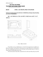
Figure 3-1 shows you the initial screen appearance on entering the Part mode with the Model
Tree, the three default datum planes, and the default options available in the Menu Manager.
THE DEFAULT DATUM PLANES
Generally, the first feature in the Part mode is the default datum planes. These datum planes
are further used to create the base feature. These datum planes act as a plane on which you can
draw a 2D sketch and then convert it to a 3D model by extruding it. These three default datum
planes are mutually perpendicular to each other. You can create any number of datum planes
for your requirement. The creation of additional datum planes is discussed in Chapter 4. In
earlier releases of Pro/ENGINEER, you need to create the default datum planes. But in this
release, a default template is provided that contains the three default datum planes and is
opened by default. However, if you do not need the default datum planes then you need to
clear the Use default template check box in the New dialog box.
Note
From this chapter onwards, most of the sketches will be sketched using the Intent Manager.
Tip: It is recommended that you always use the datum planes to create a base feature.
This is because the model created using the datum planes can be easily oriented. The
uses of datum planes are discussed in Chapter 4.
Creating Base Features 3-3
© CADCIM T© CADCIM T
© CADCIM T© CADCIM T
© CADCIM T
echnologies, USAechnologies, USA
echnologies, USAechnologies, USA
echnologies, USA
. F. F
. F. F
. F
or engineering seror engineering ser
or engineering seror engineering ser
or engineering ser
vices, contact , contact
vices, contact , contact
vices, contact
CREATING A PROTRUSION
Protrusion is defined as the process of adding material
defined by a sketched section. In Pro/ENGINEER you
have various options of adding material such as Extrude,
Revolve, Sweep, and so on. Choose Feature > Create >
Solid > Protrusion from the PART menu in the Menu
Manager. The SOLID OPTS menu is displayed as shown in
Figure 3-2.
These options can also be invoked from the Insert menu in
the menu bar. Figure 3-3 shows the method of invoking the
different options of adding material to a sketch. Some of
these protrusion options are discussed next.
Extrude
The Extrude option of the SOLIDS OPTS menu adds material defined by a sketch drawn on
a sketching plane. The material is added in the direction of feature creation.
The procedure to create a base feature using the Extrude > Solid option is explained next.
Figure 3-2 SOLID OPTS menu
Figure 3-1 The initial screen appearance after entering the Part mode
3-4 Pro/ENGINEER for Designers
© CADCIM T© CADCIM T
© CADCIM T© CADCIM T
© CADCIM T
echnologies, USAechnologies, USA
echnologies, USAechnologies, USA
echnologies, USA
. F. F
. F. F
. F
or online training, contact online training, contact
or online training, contact online training, contact
or online training, contact
1. When you choose the Feature > Create > Solid > Protrusion > Extrude > Solid >
Done from the PA RT menu in the Menu Manager or choose Protrusion > Extrude from
the Insert menu in the menu bar, the ATTRIBUTES menu is displayed as shown in
Figure 3-4. This menu has two options One Side and Both Sides.
When you select the One Side option then the sketch is extruded to one side of the
sketching plane. When you select the Both Sides option, the sketch is extruded to both
the sides of the sketching plane symmetrically. However, this concept of giving depth to
the section will be discussed later in this chapter.
2. Select the One Side option from the ATTRIBUTES menu and choose Done. The SETUP
SK PLN (Setup Sketching Plane) menu and the SETUP PLANE submenu is displayed
with the GET SELECT submenu as shown in Figure 3-5. You will be prompted to select
a datum plane or create a datum plane. The procedure to create a datum plane is discussed
in Chapter 4. Select the datum plane named FRONT from the graphics screen.
You can also use the Query Sel option from the GET SELECT submenu to select the
datum plane. To query select, choose the Query Sel option from the GET SELECT
submenu. Select a datum plane using the left mouse button. The Query Bin dialog box is
displayed highlighting the selected datum plane as shown in Figure 3-6.
Figure 3-3 Invoking the Protrusion option from the menu bar
Figure 3-4 ATTRIBUTES menu
Creating Base Features 3-5
© CADCIM T© CADCIM T
© CADCIM T© CADCIM T
© CADCIM T
echnologies, USAechnologies, USA
echnologies, USAechnologies, USA
echnologies, USA
. F. F
. F. F
. F
or engineering seror engineering ser
or engineering seror engineering ser
or engineering ser
vices, contact , contact
vices, contact , contact
vices, contact
You can also right-click on the graphics screen
to invoke the Query Sel option and use the
middle mouse button to accept the selection from
the Query Bin dialog box.
3. After selecting the datum plane the DIRECTION
submenu is displayed as shown in Figure 3-7.
The datum plane selected shows the direction
of feature creation by a red arrow. Choose the
Okay option to accept the direction shown by
the arrow. If you want to change the direction of
feature creation choose the Flip option. However,
at this stage of learning it is better to accept the
default direction.
4. The SKET VIEW (Sketch View) submenu shown in
Figure 3-8 is displayed providing the options to orient
the sketching plane. Choose the Top option from the
SKET VIEW submenu and select the TOP datum
plane to orient the sketching plane. It is recommended
to use the Default option only if you are an advanced
user of Pro/ENGINEER. The options in the SKET
VIEW submenu are discussed later in this chapter.
5. Now, you have entered the sketcher environment. You
will notice that the References dialog box is displayed
on the top right corner of the screen. The status displayed under the Reference status
area is Fully Placed. This suggests that the references are selected by default. The FRONT
datum plane is the sketching plane and is oriented parallel to the screen.
6. Turn off the display of the Model Tree by choosing the Model Tree on/off button in the
Top Toolchest. The drawing space on the graphics screen will increase by turning off the
Figure 3-5 The SETUP SK PLN menu
with the SETUP PLANE submenu and the
GET SELECT submenu
Figure 3-8 SKET VIEW submenu
Figure 3-6 The Query Bin dialog box Figure 3-7 DIRECTION submenu
3-6 Pro/ENGINEER for Designers
© CADCIM T© CADCIM T
© CADCIM T© CADCIM T
© CADCIM T
echnologies, USAechnologies, USA
echnologies, USAechnologies, USA
echnologies, USA
. F. F
. F. F
. F
or online training, contact online training, contact
or online training, contact online training, contact
or online training, contact
Model Tree and the appearance of the graphics screen is similar to that shown in Figure 3-9.
7. Use the Create lines. button to draw the right half of the I-section and then draw a vertical
center line aligned with the RIGHT datum plane. Select all the lines in the right half of
the I-section and choose the Mirror selected entities. button. You will be prompted to
select a center line. Select the center line to mirror the right half and to create the I-section
as shown in Figure 3-10. Assume the dimensions. After the I-section is sketched, choose
the Continue with the current section. button from the Right Toolchest.
8. When you choose the Continue with the current section. button from the Right Toolchest,
the SPEC TO menu is displayed as shown in Figure 3-11. The Blind option is selected by
default, choose Done. The Message Input Window is displayed with a default value for
the depth. Either accept the default value or enter a value. Choose the green check mark
on the Message Input Window or press ENTER.
9. From the PROTRUSION dialog box, choose the OK button. The required 3D model is
displayed on the graphics screen. Change the display of the part drawn from the View
toolbar by choosing the Saved view list button and selecting the Default option from
the drop-down list that appears. Figure 3-10 explains that the I-section after extrusion to
certain depth becomes a three-dimensional solid.
Figure 3-12 and Figure 3-13 shows some examples of Extrude > Solid option.
Figure 3-9 The graphics screen after entering the sketcher environment
Creating Base Features 3-7
© CADCIM T© CADCIM T
© CADCIM T© CADCIM T
© CADCIM T
echnologies, USAechnologies, USA
echnologies, USAechnologies, USA
echnologies, USA
. F. F
. F. F
. F
or engineering seror engineering ser
or engineering seror engineering ser
or engineering ser
vices, contact , contact
vices, contact , contact
vices, contact
The above steps explain how to construct a 3D model using the Extrude > Solid option. All
the menus and submenus that you came across while creating the 3D model from an I-section
are discussed next.
ATTRIBUTES menu
The options in the ATTRIBUTES menu as shown in Figure 3-14 are used to extrude the
sketch either on one side of the sketching plane or on both the sides. The options in the
ATTRIBUTES menu are discussed next.
One Side
The One Side option of the ATTRIBUTES menu
extrudes the sketch on one side of the sketching plane.
When you choose the Done option from this menu,
the SETUP SK PLN menu is displayed and you will
be prompted to select or create a sketching plane.
Figure 3-13 Model created using the Extrude
> Solid option
Figure 3-12 Model created using the Extrude
> Solid option
Figure 3-14 ATTRIBUTES menu
Figure 3-10 The I-section extruded to a certain
depth
Figure 3-11 SPEC TO menu
3-8 Pro/ENGINEER for Designers
© CADCIM T© CADCIM T
© CADCIM T© CADCIM T
© CADCIM T
echnologies, USAechnologies, USA
echnologies, USAechnologies, USA
echnologies, USA
. F. F
. F. F
. F
or online training, contact online training, contact
or online training, contact online training, contact
or online training, contact
Both Sides
The Both Sides option extrudes the sketch to both the sides of the sketching plane. When
you choose the Done option from this menu, the SETUP SK PLN menu is displayed and
you will be prompted to select or create a sketching plane.
Note
If you choose the One Side option then at the step of defining the termination depth of a feature
the SPEC TO menu is displayed and if the Both Sides option is chosen then the SPEC FROM
menu is displayed. The SPEC TO and the SPEC FROM menus are discussed later in the
chapter.
Done
After selecting one of the above two options, you have to choose Done to continue.
Quit
To quit the selections made you can choose the Quit option. When you choose the Quit
option, you have the option to either continue with sketch creation or abort the new object
you started. This can be done using the PROTRUSION (Feature Creation) dialog box
that is discussed later in this chapter.
DIRECTION submenu
The DIRECTION submenu is used to set the direction of feature creation. The direction of
feature creation is defined as the direction in which the feature is created with respect to the
sketching plane. This direction is displayed by a red arrow
on the graphics screen. The options in the DIRECTION
submenu are Flip and Okay, see Figure 3-15. The Flip
option reverses the direction of feature creation. You will
notice that when you choose this option, the red arrow
points in the reverse direction suggesting that the
direction of feature creation is reversed.
The direction of the red arrow depends on the orientation of the feature. If material has to be
added to a feature then the arrow by default
points in the direction toward the user, that
is, out of the screen. If material has to be
removed from a feature then by default the
arrow points into the screen.
The display of the arrow when the viewing
direction is normal to the sketching plane is
shown in Figure 3-16. However, if you spin
the model using the CTRL+middle mouse
button then the direction of the arrow can be
easily recognized.
SKET VIEW submenu
The SKET VIEW submenu shown in Figure 3-17 is displayed after you have specified the
Figure 3-15 DIRECTION submenu
Figure 3-16 Display of the red arrow
Creating Base Features 3-9
© CADCIM T© CADCIM T
© CADCIM T© CADCIM T
© CADCIM T
echnologies, USAechnologies, USA
echnologies, USAechnologies, USA
echnologies, USA
. F. F
. F. F
. F
or engineering seror engineering ser
or engineering seror engineering ser
or engineering ser
vices, contact , contact
vices, contact , contact
vices, contact
sketching plane. The options in this submenu are used
to specify a horizontal or vertical reference for the
sketching plane. Generally, your view is normal to the
sketching plane you have selected. In order to orient the
sketching plane normal to the viewing direction, you have
to specify a plane or a planar surface that is perpendicular
to the sketching plane. Except the Default option, select
any option from this submenu and then select a datum
plane or a planar surface; the plane selected will be
oriented in direction with respect to the sketch. For
example, if you select the To p option from the submenu
and then select the RIGHT datum plane, then the
RIGHT datum plane will be oriented to the top.
Before you proceed further, you need to understand the three
default datum planes that are displayed when you open a new
part file. If you see the feature from the right then your viewing
direction is normal to the RIGHT datum plane. If you see the
feature from the top then your viewing direction is normal to
the TOP datum plane. Similarly, if you see the feature from
the front then your viewing direction is normal to the FRONT
datum plane. You can view the feature that you have created
from different directions using the Saved view list drop-down
list shown in Figure 3-18.
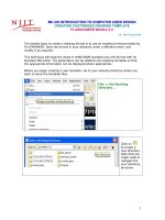
The options in the SKET VIEW submenu are very important and you need to select the
reference plane very carefully, especially for the base feature. The importance of selecting the
reference plane is explained using Figure 3-19. This figure shows two cases where the sketching
plane for both the solid models is the same, the same sketch is extruded, the same option Top
was chosen from the SKET VIEW submenu but different reference planes were selected. The
same sketch was used to extrude for both the models and the top curve in the sketch was on the
top while sketching. Note, the difference in orientation of the resultant models in their default
trimetric orientations. The model can be oriented in its default orientation using CTRL+D.
SPEC TO or SPEC FROM menu
When you choose the One Side option from the ATTRIBUTES menu, the SPEC TO menu is
displayed as shown in Figure 3-20. If you choose the Both Sides option from the ATTRIBUTES
menu, the SPEC FROM menu is displayed as shown in the Figure 3-21. The options in these
menus are used to specify the method of feature termination. These options are discussed
next.
Blind
The Blind option is one of the most commonly used option to give extrusion depth by
specifying a particular depth value. When you select this option and choose Done, the
Message Input Window is displayed with a default value for depth. You can enter a value
in this window and press ENTER. The material is added in the direction shown by the red
arrow. The depth of extrusion given by this value can be modified, if needed. If you
Figure 3-17 SKET VIEW submenu
Figure 3-18 The Saved view
list drop-down list
3-10 Pro/ENGINEER for Designers
© CADCIM T© CADCIM T
© CADCIM T© CADCIM T
© CADCIM T
echnologies, USAechnologies, USA
echnologies, USAechnologies, USA
echnologies, USA
. F. F
. F. F
. F
or online training, contact online training, contact
or online training, contact online training, contact
or online training, contact
choose the Blind option from the SPEC FROM menu, the material is added equally in
both the direction of the sketching plane.
Figure 3-20 The SPEC TO menu
Figure 3-21 The SPEC FROM menu
Figure 3-19 Importance of selecting reference planes
Creating Base Features 3-11
© CADCIM T© CADCIM T
© CADCIM T© CADCIM T
© CADCIM T
echnologies, USAechnologies, USA
echnologies, USAechnologies, USA
echnologies, USA
. F. F
. F. F
. F
or engineering seror engineering ser
or engineering seror engineering ser
or engineering ser
vices, contact , contact
vices, contact , contact
vices, contact
Note
In the case of material removal processes such as cut, slots, holes, and so on, the material is
removed up to the specified depth in the direction shown by the arrow.
2 Side Blind
The 2 Side Blind option is available only when the Both Sides option is selected from the
ATTRIBUTES menu. This option allows you to separately enter the extrusion depth for
the two sides of the sketching plane.
Thru Next
The Thru Next option extrudes the sketch up to the next surface it meets. Remember that
the feature is terminated at the next surface.
Thru All
When you choose the Thru All option, the feature intersects all the surfaces it encounters.
This is the most commonly used option for the material removal features such as cut,
holes, slots and so on. Note that the Thru All option restores the design intent of the part
by adjusting the depth of extrusion if the depth of the original feature or model is adjusted.
Thru Until
This option extrudes a feature until the surface specified by the user. When you select this
option you are prompted to select a surface to extrude until. A datum plane cannot be the
surface of termination for this option.
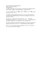
Figure 3-22 explains the use of all the thru options available in the SPEC TO or SPEC FROM
menu.
Note
In Figure 3-22, the cylindrical features are drawn on a datum plane that is at certain offset
distance from the top planar surface of the base feature. The datum plane is not shown in the
figure. The creation of datum planes will be discussed in Chapter 4.
Figure 3-22 The thru options
3-12 Pro/ENGINEER for Designers
© CADCIM T© CADCIM T
© CADCIM T© CADCIM T
© CADCIM T
echnologies, USAechnologies, USA
echnologies, USAechnologies, USA
echnologies, USA
. F. F
. F. F
. F
or online training, contact online training, contact
or online training, contact online training, contact
or online training, contact
Upto Pnt/Vtx
The Upto Pnt/Vtx option extrudes a sketch up to the selected datum point or vertex. The
datum points are discussed in later chapters.
Upto Curve
The Upto Curve option extrudes a sketch up to a plane passing through a selected edge,
axis, or datum curve. The datum curves are explained in Chapter 7.
Upto Surface
When you use the Upto Surface option, a sketch is extruded up to the selected surface.
Done
Choose the Done option after selecting the feature termination options available in the
SPEC TO or SPEC FROM menu.
Feature Creation dialog box
This dialog box can be used at any time when you quit a particular menu or submenu, when
you abort the sketcher environment, when you have given the depth of extrusion, and so on.
This dialog box contains all the feature parameters. You can change their definitions at any
time. If you are creating a protrusion, then this dialog box is called the PROTRUSION dialog
box; if shell is being created, then this dialog box is called the SHELL dialog box. Hence, the
name of the Feature Creation dialog box depends on the feature that you create. This dialog
box is very useful when you are modifying a feature. The various options under this dialog box
shown in Figure 3-23 are discussed next.
Element
The Element column lists all the feature parameters available in the current sketch.
Tip: The following points should be remembered while using the Thru options:
1. Thru options are used when you want the feature to terminate on a specified
surface.
2. Use the Thru Next option when you want the feature to terminate on the first
surface it intersects in the direction of feature creation.
3. Use the Thru All option when you want the feature to terminate on the last
surface available in the direction of feature creation.
4. When you use the Thru Until option, you are prompted to select the termination
surface.
5. The features created using the Thru options do not have a dimension associated
with them, and hence they cannot be modified by changing the dimension value.
However, changing the terminating surface changes the depth of the feature. You
will understand this better when you learn the modification of an existing feature.
Creating Base Features 3-13
© CADCIM T© CADCIM T
© CADCIM T© CADCIM T
© CADCIM T
echnologies, USAechnologies, USA
echnologies, USAechnologies, USA
echnologies, USA
. F. F
. F. F
. F
or engineering seror engineering ser
or engineering seror engineering ser
or engineering ser
vices, contact , contact
vices, contact , contact
vices, contact
Info
Under the Info column all the feature parameters
are defined. If a feature parameter is not defined
then Pro/ENGINEER shows Required in front
of the feature parameter.
Define
The Define button is used to define a feature
parameter. This is used if you want to change
the feature definition. Select the feature
parameter from the Element column and then
choose the Define option. The menu
corresponding to the feature parameter is
displayed. For example, if you select Direction under the Element column and then choose
the Define button, the DIRECTION menu is displayed.
Refs
When you select any feature parameter under the Element column, and then select the
Refs option from the dialog box, the references, if any, related to the feature parameter
are highlighted on the graphics screen.
Info
The Info button when chosen provides information about the feature parameter selected
from the Element column. When you select the feature parameter and then choose the
Info button, the INFORMATION WINDOW is displayed. This window contains all the
information about the selected feature parameter.
Preview
The Preview button when chosen shows the preview of the part you have created. It is
recommended to use this button before choosing the OK button so that you can preview
the model and if required, the definition parameter can be modified from the Feature
Creation dialog box.
OK
The OK button is used to complete the feature
creation. When you choose this button, the
Feature Creation dialog box is closed and the
feature is created.
Cancel
When you choose this button the Confirm
Cancel dialog box is displayed as shown in
Figure 3-24. This button is chosen when you
want to cancel feature creation.
Extrude > Thin
The Extrude > Thin option is used to create thin parts with specified thickness. Unlike the
Figure 3-23 PROTRUSION dialog box
Figure 3-24 Confirm Cancel dialog box
3-14 Pro/ENGINEER for Designers
© CADCIM T© CADCIM T
© CADCIM T© CADCIM T
© CADCIM T
echnologies, USAechnologies, USA
echnologies, USAechnologies, USA
echnologies, USA
. F. F
. F. F
. F
or online training, contact online training, contact
or online training, contact online training, contact
or online training, contact
surface models, a model created using the Extrude >
Thin combination has mass properties that can be
calculated. The SOLID OPTS menu shown in
Figure 3-25 contains different options of adding material
to the sketch drawn. The Extrude > Solid option was
discussed earlier. Here, the Extrude > Thin option is
discussed.
This combination is used to create thin parts having a certain
thickness. When you regenerate the section created, you
are prompted to specify the side of the section where the
material will be added. After specifying the side of material
addition, you are prompted to enter the thickness value in
the Message Input Window that is displayed.
While using the Extrude > Thin combination, after the sketch
is completed and you exit the sketcher environment, the
THIN OPT menu is displayed as shown in Figure 3-26.
Figure 3-27 shows the arrow pointing away from the side of
the section wall where the material will be added. If you want
to change the direction of the arrow, choose the Flip option
from the THIN OPT menu. Figure 3-28 shows the thickness
of the material added to one side of the wall pointed by the
arrow.
If you choose the Both option from the THIN OPT menu, the material will be added
symmetrically to both the sides of the section wall as shown in Figure 3-29. Figure 3-30 shows
the model created using the Extrude > Thin options.
Revolve
The Revolve option revolves the sketched section through the specified angle about a center
Figure 3-25 SOLID OPTS menu
Figure 3-26 THIN OPT menu
Figure 3-28 Using the One Side option in
the Extrude > Thin option
Figure 3-27 The Extrude > Thin option
Creating Base Features 3-15
© CADCIM T© CADCIM T
© CADCIM T© CADCIM T
© CADCIM T
echnologies, USAechnologies, USA
echnologies, USAechnologies, USA
echnologies, USA
. F. F
. F. F
. F
or engineering seror engineering ser
or engineering seror engineering ser
or engineering ser
vices, contact , contact
vices, contact , contact
vices, contact
line. The Protrusion > Revolve option is used to add material and the Cut > Revolve option
is used to remove material. The revolved feature can be revolved on one side of the sketching
plane or on both the sides of the sketching plane. This is achieved by selecting the One Side
option or the Both Sides option from the ATTRIBUTES menu. Some of the points to be kept
in mind while creating a revolve feature are given next.
1. The section drawn should be a closed section for the Revolve > Solid combination.
2. The section sketch of a revolve feature will not be completed until you have drawn a center
line.
3. The section drawn should be on one side of the center line.
4. If there are more than one center lines in the sketch then Pro/ENGINEER uses the center
line that is drawn first and considers it the axis of rotation.
The combinations of Revolve option can be Revolve > Solid or Revolve > Thin.
Revolve > Solid
Figure 3-31 and Figure 3-32 explain the Revolve > Solid combination.
Revolve > Thin
The Revolve > Thin combination is used to create revolved features having a certain thickness.
Unlike the Revolve > Solid combination, in Revolve > Thin the section need not be a closed
loop. When you exit the sketcher environment after the section is created, you are prompted to
specify the side of the section where the material will be added. After specifying the side for
the material addition, you will be prompted to enter the thickness value in the Message Input
Window.
The Revolve > Thin combination is explained in Figure 3-33 and Figure 3-34. Unlike the
Figure 3-30 Model created using the Extrude >
Thin option
Figure 3-29 Using the Both Sides option in
the Extrude > Thin option
3-16 Pro/ENGINEER for Designers
© CADCIM T© CADCIM T
© CADCIM T© CADCIM T
© CADCIM T
echnologies, USAechnologies, USA
echnologies, USAechnologies, USA
echnologies, USA
. F. F
. F. F
. F
or online training, contact online training, contact
or online training, contact online training, contact
or online training, contact
surface models, the model created using the Revolve > Thin combination has mass properties.
When you use the above two combinations to create a feature
and the sketch is completed, the REV TO menu is displayed
as shown in Figure 3-35. The options in this menu are
discussed next.
Variable
When you select the Variable option and choose Done,
the Message Input Window is displayed. In this window,
you need to enter the angle of revolution for the sketch
of the revolved feature. The value should be in the range
of 0.001 to 360. The value entered is controlled by a
dimension and can be modified later.
90
The 90 option revolves the sketch to a fixed angle of
90-degree.
Figure 3-32 Model created using the Revolve
> Solid option
Figure 3-31 Model created using the Revolve
> Solid option
Figure 3-34 Model created using the Revolve
> Thin option
Figure 3-33 Model created using the Revolve
> Thin option
Figure 3-35 The REV TO menu
Creating Base Features 3-17
© CADCIM T© CADCIM T
© CADCIM T© CADCIM T
© CADCIM T
echnologies, USAechnologies, USA
echnologies, USAechnologies, USA
echnologies, USA
. F. F
. F. F
. F
or engineering seror engineering ser
or engineering seror engineering ser
or engineering ser
vices, contact , contact
vices, contact , contact
vices, contact
180
The 180 option revolves the sketch to a fixed angle of 180-degree.
270
When you select the 270 option and choose Done, the sketched section is revolved to a
fixed angle of 270-degree.
360
The 360 option revolves the sketch to a fixed angle of 360-degree.
Note
If you have chosen the Both Sides option in the ATTRIBUTES menu, the REV FROM menu
is displayed. The options in the REV FROM menu are the same as in the REV TO menu but
their functionality is different. If you enter a value for the angle of rotation, the material is added
equally to both the sides of the sketching plane.
UpTo Pnt/Vtx
When you select the UpTo Pnt/Vtx option and choose Done, you are prompted to select a
point or vertex. The sketch will be revolved until it meets the selected vertex or point.
If you have chosen the Both Sides option from the ATTRIBUTES menu and select the
Upto Pnt/Vtx option to specify the angle of revolution then after choosing Done from the
REV FROM menu, you need to select a reference point or vertex from where the angle of
revolution starts. After you specify a point or a vertex, the REV TO menu is displayed with
only two options: Upto Pnt/Vtx and the Upto Plane option. These options are used to
specify the termination of the feature.
UpTo Plane
The UpTo Plane option revolves the sketch up to the selected plane. When you select this
option and choose Done, you are prompted to select the plane up to which the section will
be revolved. You can flip the arrow to specify on which side of the plane the feature should
terminate. This is because a surface always have two surface normal vectors acting in the
opposite directions. Hence, it becomes necessary to specify the side of the selected plane
or surface on which the revolve section will terminate.
When the Upto Plane option is used from the REV FROM menu, you need to specify the
plane from where the angle of revolution starts. After specifying the plane, the REV TO
menu is displayed to use the reference option and specify the plane or a vertex on which
the feature will terminate.
PARENT CHILD RELATIONSHIP
Every model created in Pro/ENGINEER is composed of features that in some way or the other
are related to other features in the model. The feature that occurs first in the Model Tree is
called the parent feature, and any feature(s) that is related to this feature is called the child
feature(s).
There are two types of relationships that can exist between two features, Implicit relationship
3-18 Pro/ENGINEER for Designers
© CADCIM T© CADCIM T
© CADCIM T© CADCIM T
© CADCIM T
echnologies, USAechnologies, USA
echnologies, USAechnologies, USA
echnologies, USA
. F. F
. F. F
. F
or online training, contact online training, contact
or online training, contact online training, contact
or online training, contact
and Explicit relationship.
Implicit Relationship
This type of relationship exists when the two features are related through equations. These
equations are formed using relations. Relations are explained in Chapter 8.
Explicit Relationship
The explicit relationship is developed when a feature is used to create another feature. This
means that one of the planar surfaces of a feature is used to create another feature. In this case,
the first feature is called the parent feature and the second feature is called the child feature of
the first feature. Another example of this type of relationship is, when a hole is referenced to
the edges of the surface it is placed on or to the edges of some other surface. In this case, the
hole is the child feature of the feature it is referenced from.
If the parent feature is modified then the child feature is also modified. If the parent feature is
deleted then the child feature is also deleted. For example, if you have used the three default
datum planes to create the base feature and you delete any one of the datum planes, the base
feature is also deleted.
TUTORIALS
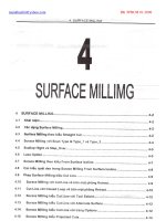
In this tutorial you will create the model shown in Figure 3-36. The dimensions for the model
are shown in Figure 3-37. (Estimated time: 30 min)
Figure 3-37 Front view and the right-side view of
the model with dimensions
Figure 3-36 Isometric view of the model
Tutorial 1
Tip: If you want to check the parent-child relationship of features in a model, choose
Info > Parent/Child from the menu bar. You are prompted to select a feature. After
you select the feature, the Reference Information Window is displayed. All the
child features of the selected feature are displayed in the Children of Current Feature
area and all the parent features are displayed in the Parents of Current Feature
area.
Creating Base Features 3-19
© CADCIM T© CADCIM T
© CADCIM T© CADCIM T
© CADCIM T
echnologies, USAechnologies, USA
echnologies, USAechnologies, USA
echnologies, USA
. F. F
. F. F
. F
or engineering seror engineering ser
or engineering seror engineering ser
or engineering ser
vices, contact , contact
vices, contact , contact
vices, contact
The following steps outline the procedure for creating this model:
a. Set the working directory and create a new object file in the Part mode.
b. First examine the model and then determine the type of protrusion for the model.
c. Select the sketching plane for the model and orient it parallel to the screen.
d. Draw the sketch using the sketching tools and apply constraints and dimensions.
e. Extrude the sketch to the given distance.
Setting the Working Directory
When Pro/ENGINEER session is started, the first task is to set the working directory. A working
directory is a directory on your system where you can save the work done in the current session
of Pro/ENGINEER. You can set any directory existing on your system as the working directory.
Since this is the first tutorial of this chapter, you need to create a folder named c03, if it does
not exist.
1. Choose File > Set Working Directory from the menu bar. The Select Working Directory
dialog box is displayed.
2. Browse and select C:\ProE. It is assumed that the ProE folder exists.
3. Choose the New Directory button in the Select Working Directory dialog box.
The New Directory dialog box is displayed.
4. Type c03 in the New Directory edit box. Choose OK from the dialog box. You have
created a folder named c03 in C:\ProE.
5. Choose OK from the Select Working Directory dialog box. You have set the working
directory to C:\ProE\c03.
Creating New Object File
Solid models are created in the Part mode of Pro/ENGINEER. The file extension for the files
created in this mode is .prt.
1. Choose the Create a new object button from the Top Toolchest. The New dialog box is
displayed. The Part radio button is selected by default in the Type area and the Solid
radio button is selected by default in the Sub-type area of the New dialog box.
Note
Before choosing the OK button from the New dialog box, make sure that the Use default template
check box is selected. If this check box is cleared then the default datum planes will not be
displayed on the graphics screen and you will have to create them manually.
2. Enter the file name as c03tut1 in the Name edit box and choose the OK button.
3-20 Pro/ENGINEER for Designers
© CADCIM T© CADCIM T
© CADCIM T© CADCIM T
© CADCIM T
echnologies, USAechnologies, USA
echnologies, USAechnologies, USA
echnologies, USA
. F. F
. F. F
. F
or online training, contact online training, contact
or online training, contact online training, contact
or online training, contact
The three default datum planes are displayed on the graphics screen. The Model Tree
also appears on the left of the graphics screen.
3. Exit the Model Tree by choosing the Model Tree on/off button from the Model
Display toolbar in the Top Toolchest.
Selecting the Protrusion Option
The given solid model is created after extruding the sketch to a distance of 75. Therefore, the
Extrude > Solid combination will be used to create the model. There are two methods to
invoke the Extrude option. The first method is to use the menu bar present on the top of the
screen and the second method is to use the Menu Manager present on the right side of the
graphics screen.
1. Choose Insert > Protrusion > Extrude from the menu bar or choose PA RT > Feature >
Create > Solid > Protrusion > Extrude > Solid > Done from the Menu Manager. The
PROTRUSION dialog box is displayed on the top right corner of the screen and the
ATTRIBUTES menu is displayed below it.
Note that in the PROTRUSION dialog box, all the feature parameters are displayed as
Required, except the Attributes parameter. In the Attributes field of the Info column, the
information about the attributes is Defining. This means that you are defining the attributes
using the ATTRIBUTES menu that is displayed with the PROTRUSION dialog box.
The ATTRIBUTES menu helps you to determine whether you want to extrude the sketch
on one side of the sketching plane or on both the sides of the sketching plane.
2. The One Side option is selected by default in the ATTRIBUTES menu. Choose Done.
You are prompted to select or to create a sketching plane. You do not need to create a
sketching plane since one of the default datum planes will be selected as the sketching plane.
Selecting the Sketching Plane
To create the sketch for the extruded feature, you first need to select the sketching plane for
the model. The FRONT datum plane will be selected as the sketching plane. The sketching
plane is selected such that the direction of extrusion of the solid model is perpendicular to it.
From the isometric view of the model shown in Figure 3-36, it is evident that the direction of
extrusion of the model is perpendicular to the FRONT datum plane.
1. Select the FRONT datum plane as the sketching plane. You are prompted to specify the
direction of feature creation.
The message “Arrow shows direction of feature creation. Pick FLIP or OKAY.” is displayed
in the Message Area. A red arrow is displayed on the FRONT datum plane and points in
the direction of feature creation. Direction of feature creation is the direction in which the
sketch will be extruded.
2. Choose the Okay option from the DIRECTION submenu. The SKET VIEW submenu is
displayed.
Creating Base Features 3-21
© CADCIM T© CADCIM T
© CADCIM T© CADCIM T
© CADCIM T
echnologies, USAechnologies, USA
echnologies, USAechnologies, USA
echnologies, USA
. F. F
. F. F
. F
or engineering seror engineering ser
or engineering seror engineering ser
or engineering ser
vices, contact , contact
vices, contact , contact
vices, contact
You need to select a horizontal or vertical reference to orient the sketching plane. You can
specify the reference by using the options in the SKET VIEW submenu.
3. Choose the Right option from the SKET VIEW submenu and select the RIGHT datum
plane. As mentioned earlier, this plane will be perpendicular to the sketching plane and
the sketching plane will be parallel to the screen.
Specifying References
Now, you have entered the sketcher environment and you will notice that the Intent Manager
is on by default. The References dialog box is displayed on the top right corner of the screen
overlapping the PROTRUSION dialog box. You will be prompted to select a perpendicular
surface, an edge, or a vertex relative to which the section will be dimensioned or constrained.
Pro/ENGINEER does not use any coordinate system, and therefore it becomes necessary for
the user to locate the sketch with some reference. The reference can consist of part surfaces,
datums, edges, or axes.
The status displayed in the Reference status area is Fully Placed. This indicates that
the references required for the sketch are automatically defined.
1. Choose the Close button from the References dialog box to exit it.
The FRONT datum plane is the sketching plane and is parallel to the graphics screen.
This can be verified by performing the next step.
2. Spin the datum planes using the CTRL+middle mouse button. Now, from this view of the
datum planes, it is clear that the sketching plane was parallel to the graphics screen and
the other two datum planes were perpendicular to the sketching plane.
The above step is just to understand the orientation of the three default datum planes
when you enter the sketcher environment.
3. Choose the Orient the sketching plane parallel to the screen button from the
Sketcher toolbar in the Top Toolchest. The sketching plane and the other two
perpendicular datum planes are reoriented on the screen.
Note
It is recommended to use Intent Manager for creating the sketch. All the tutorials from this
chapter onwards are explained using the Intent Manager.
Drawing the Sketch
You need to draw the sketch of the solid model that will later be extruded to create the 3D
model.
1. Choose the Create rectangle. button from the Right Toolchest.
2. Draw a rectangle by defining its lower left corner and the upper right corner. The rectangle
is created and weak dimensions are applied to it.
3-22 Pro/ENGINEER for Designers
© CADCIM T© CADCIM T
© CADCIM T© CADCIM T
© CADCIM T
echnologies, USAechnologies, USA
echnologies, USAechnologies, USA
echnologies, USA
. F. F
. F. F
. F
or online training, contact online training, contact
or online training, contact online training, contact
or online training, contact
You will notice that strong vertical and horizontal constraints are applied to the lines
composing the rectangle. This is because drawing a rectangle is itself a constraint to the
lines composing the rectangle.
3. Choose the Select one item at a time - shift to gather more than one item. button
from the Right Toolchest.
4. Select the right vertical line; the line turns red in color. Press DELETE to delete the right
vertical line. The sketch after deleting the vertical line is shown in Figure 3-38.
5. Now, draw the lines and the arc as shown in Figure 3-39. Some weak dimensions and
constraints are applied to the sketch.
Note
As evident from Figure 3-39, strong constraints are also applied to the sketch. These strong
constraints are applied while sketching. However, if these strong constraints are not applied
when you draw the sketch, then you need to apply these constraints manually.
In Figure 3-39, the center of the arc and the TOP datum plane are aligned by default.
In case the center of the arc is not aligned to the TOP datum plane then you need to
align them. To align the center, choose the Create same points, points on entity or
collinear constraint button from the Constraints dialog box. Select the center of the arc and
then select the TOP datum plane. Now, the center and the datum plane are aligned.
Applying Constraints to the Sketch
You need to apply equal length constraints to the sketch in order to maintain the design intent
of the model.
1. Choose Impose sketcher constraints on the section. button from the Right
Toolchest. The Constraints dialog box is displayed.
Figure 3-39 Sketch before modifying the
weak dimensions
Figure 3-38 Outer loop of the sketch with weak
dimensions
Creating Base Features 3-23
© CADCIM T© CADCIM T
© CADCIM T© CADCIM T
© CADCIM T
echnologies, USAechnologies, USA
echnologies, USAechnologies, USA
echnologies, USA
. F. F
. F. F
. F
or engineering seror engineering ser
or engineering seror engineering ser
or engineering ser
vices, contact , contact
vices, contact , contact
vices, contact
2. Choose the Create Equal Lengths, Equal Radii, or Same Curvature constraint
button and select the two vertical lines on the right side of the sketch. The weak
constraint L
2
was applied when the two vertical lines were drawn. Now, the equal
length constraint L
2
is applied to both the lines. The constraint labels like L
2
or L
3
vary
from sketch to sketch.
3. Select the two horizontal lines that are connected through an arc to apply on them the
equal length constraint. The equal length constraint L
2
is applied to both the lines and the
constraint symbol L
2
on the two right vertical lines is changed to L
1.
The sketch after applying the equal length constraints is shown in Figure 3-40.
Dimensioning the Sketch
Although some weak dimensions are applied to the sketch, yet you need to add a dimension to
the sketch.
1. Choose the Create defining dimension. button from the Right Toolchest.
2. Select the center of the arc and the upper right vertical line and place the dimension as
shown in Figure 3-41.
Note
If the dimensions in your sketch are different from those shown in Figure 3-41, add the missing
dimensions and delete the dimensions that are not required.
Modifying the Dimensions
You need to modify the dimension values of the sketch. You will notice that the default
dimensions shown in Figure 3-41 also include the length and width of the rectangle and the
distance of the sketched section from the selected references. It is recommended to draw the
base feature symmetrical with the other two datum planes. Hence, the distance from the RIGHT
datum plane is 100 (200 divided by 2 is equal to 100).
Figure 3-41 Dimension added to the sketch
Figure 3-40 Equal length constraints applied to
the sketch
3-24 Pro/ENGINEER for Designers
© CADCIM T© CADCIM T
© CADCIM T© CADCIM T
© CADCIM T
echnologies, USAechnologies, USA
echnologies, USAechnologies, USA
echnologies, USA
. F. F
. F. F
. F
or online training, contact online training, contact
or online training, contact online training, contact
or online training, contact
1. Select the sketch and dimensions using CTRL+ALT+A.
2. Choose the Modify the values of dimensions, geometry of splines, or text
entities. button from the Right Toolchest. The Modify Dimensions dialog box is
displayed.
All the dimensions in the sketch are displayed in this dialog box and each dimension has
a separate thumbwheel and an edit box. You can use the thumbwheel or the edit box to
modify the dimensions. It is recommended to use the edit boxes to modify the dimensions
if the change in the dimension value is large.
3. Clear the Regenerate check box. If you clear this check box, then any modification in a
dimension value does not update the sketch during the modification. The dimensions will
be modified after you exit the Modify Dimensions dialog box. It is recommended to clear
the Regenerate check box when more than one dimension has to be modified.
4. Modify all the dimensions one by one as shown in Figure 3-42. You will notice that the
dimension you select in the Modify Dimensions dialog box is enclosed in a yellow box on
the graphics screen.
5. After modifying all the dimensions, choose the Regenerate the section and close
the dialog button from the Modify Dimensions dialog box. A message Dimension
modifications successfully completed. is displayed in the Message Area.
6. Choose the Continue with the current section. button to exit the sketcher
environment.
Specifying the Depth of Extrusion
Next, you need to specify the depth of extrusion for the sketch. The SPEC TO menu is displayed
and you are prompted to specify the depth of extrusion in the direction indicated by the
arrow.
1. Choose the Saved view list button from the View toolbar in the Top Toolchest.
Choose the Default option from the drop-down list.
The default trimetric view is displayed as shown in Figure 3-43. This display gives you a
better view of the sketch in the 3D space. The red colored arrow is also displayed on the
model, indicating the direction of extrusion.
2. The Blind option in the SPEC TO menu is selected by default. Choose Done. You will be
prompted to enter the depth of extrusion in the Message Input Window that is displayed.
3. Enter 75 and choose the green check mark button on the Message Input Window or
press ENTER.
The message “All elements have been defined. Select element(s) or action(s) from dialog
box.” is displayed in the Message Area.
Creating Base Features 3-25
© CADCIM T© CADCIM T
© CADCIM T© CADCIM T
© CADCIM T
echnologies, USAechnologies, USA
echnologies, USAechnologies, USA
echnologies, USA
. F. F
. F. F
. F
or engineering seror engineering ser
or engineering seror engineering ser
or engineering ser
vices, contact , contact
vices, contact , contact
vices, contact
4. Choose Preview from the
PROTRUSION dialog box. You can see
the preview of the feature created before
confirming it.
5. Choose the OK button from the
PROTRUSION dialog box. The
message “PROTRUSION has been
created successfully.” is displayed in
the Message Area.
The completed model is shown in
Figure 3-44.
Saving the Model
1. Choose the Save option from the File menu or choose the Save the active object
button from the Top Toolchest. The Message Input Window is displayed with
the name of the object file that you had specified earlier.
2. Press ENTER or choose the green check mark on the Message Input Window to save the
file.
Closing the Current Window
The given model is created and is also saved. Now, you can close the current window.
1. Choose the Close Window option from the File menu or choose the Close option from
the Window menu. Both menus are available in the menu bar.
Figure 3-43 Arrow showing the direction of feature
creation
Figure 3-42 Sketch after modifying the
dimensions
Figure 3-44 Default trimetric view of the model