CREATING CUSTOMIZED DRAWING TEMPLATE
Bạn đang xem bản rút gọn của tài liệu. Xem và tải ngay bản đầy đủ của tài liệu tại đây (433.78 KB, 20 trang )
1
ME-430 INTRODUCTION TO COMPUTER AIDED DESIGN
CREATING CUSTOMIZED DRAWING TEMPLATE
Pro/ENGINEER Wildfire 3.0
Dr. Herli Surjanhata
The easiest ways to create a drawing format is to use an existing format provided by
Pro/ENGINEER. Save the format in your directory under a different name, and
modify it as required.
This technique will keep the sheet in ANSI/ASME standard size and format with its
standard title block. The parameters can be added to the drawing template so that
the appropriate information can be displayed where appropriate.
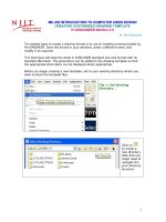
Before you begin creating a new template, set to your working directory where you
want to store the template files.
File -> Set Working
Directory…
Click on
to create a
new directory.
Note that you
might need to
navigate the
your directory
structure
2
Enter the name of directory
e.g. DrawingTemplates.
OK.
Click on
To accept
specified
working
directory.
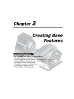
File -> Open
Or click on
.
The File Open dialog box appears.
3
Click on
Select
System
Formats.
4
Select c.frm
– a “C” size
format.
Click Open.
You can
create any
number of
personal
format using
this method,
e.g. b.frm or
a.frm.
The c.frm template is opened as shown below.
Save the c.frm under different name such as njit_c_format.frm.
5
File -> Save a Copy…
Enter the New Name
e.g. njit_c_format.
Click OK.
6
File ->
Erase ->
Current
Click on Yes.
Open the newly save template file.
Click on
.
The File Open dialog box appears.
7
Select the template
njit_c_format.frm.
Click Open.
Click
to zoom in the title block area
– see figure below.
8
For every drawing, the title block is filled with standard data or data unique to the
design. There are two types of text in Pro/ENGINEER:
1. Parameter text that will automatically reflect the design when the format is
added to a drawing in DRAWING MODE. Note that there are two different
types of parameters that can be used in a format: Pro/ENGINEER parameters
(e.g. &model_name, &scale etc) and user-defined parameters (e.g. material
etc.)
2. Plain text which does not change when the format is added. Example of plain
text is company name etc.
Add the plain text to the title block.
Click on Create a note icon
, or select
Insert -> Node.
Select Make Note.