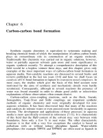
Chapter 6 Options Aiding Construction of Parts-II
Bạn đang xem bản rút gọn của tài liệu. Xem và tải ngay bản đầy đủ của tài liệu tại đây (593.67 KB, 39 trang )
Chapter
6
Options Aiding
Construction of Parts-II
After completing this chapter you will be able to:
• Create Linear pattern.
• Create Rotational pattern.
• Create Reference pattern.
• Use the Copy option.
• Use the Move option.
• Use the Mirror option.
• Use the Mirror Geom option.
Learning Objectives
6-2 Pro/ENGINEER for Designers
© CADCIM T© CADCIM T
© CADCIM T© CADCIM T
© CADCIM T
echnologies, USAechnologies, USA
echnologies, USAechnologies, USA
echnologies, USA
. F. F
. F. F
. F
or online training, contact online training, contact
or online training, contact online training, contact
or online training, contact
In this chapter you will learn about the different methods of duplicating the existing features.
In Pro/ENGINEER, you can duplicate a feature by using the following methods:
• Pattern
• Copy
• Mirror
PATTERN
Patterns are one or two dimensional incremental array of features created from a single feature
called the parent feature or the leader. When a pattern is created, the leader also becomes a
part of the pattern. When you pattern a feature, Pro/ENGINEER prompts you to specify the
total number of features to be created including the one that is being patterned and the
increment in the dimensions if required.
Uses of Patterns
Patterns are very helpful in solid modeling and they speed up the model creation. The uses of
patterns in solid modeling are discussed next.
1. Patterns create multiple copies of a feature, and hence save time of creating the features
individually.
2. All the instances in a pattern, including the parent feature, act as a single feature. Therefore,
they can easily be suppressed or mirrored.
3. All the instances in a pattern are related parametrically. Hence, you can modify the number
of instances in a pattern, the spacing between the instances, and other parameters.
4. If the dimensions of the parent feature are modified then the dimensions of the child
features are also modified.
Pattern Types
In Pro/ENGINEER, two types of patterns can be created. They are dimensional and reference
patterns.
In the dimensional patterns, the existing dimensions of the parent feature are used to create a
pattern. This pattern can be created in one direction or two directions. When you choose the
option to create the pattern in the second direction, all instances that are created in the first
direction are also created in the second direction. You need to specify the increment value for
the instances. You can enter a positive or a negative value of the increment. Once you have
specified the increment value in a direction, the system creates the specified number of instances
(including the parent feature) in that direction.
In the reference pattern, an existing pattern is referenced to create a new pattern. In this type
of pattern, the parent feature of the new pattern should be referenced to the parent feature of
the existing pattern. Figure 6-1 shows a rib feature that is referenced to the parent hole feature.
In this figure, the parent rib feature is created on a plane that was created on the fly using the
Options Aiding Construction of Parts-II 6-3
© CADCIM T© CADCIM T
© CADCIM T© CADCIM T
© CADCIM T
echnologies, USAechnologies, USA
echnologies, USAechnologies, USA
echnologies, USA
. F. F
. F. F
. F
or engineering seror engineering ser
or engineering seror engineering ser
or engineering ser
vices, contact , contact
vices, contact , contact
vices, contact
Make Datum option while creating the rib feature. This plane passes through the axis of the
parent hole feature. Hence, a relationship is built between the parent rib feature and the
parent hole feature. Now, when you select the rib feature to pattern, the pattern shown in
Figure 6-2 is created without specifying the increment in dimensions.
Note
If you create the datum plane passing through the axis of the hole using the Insert a datum
plane. button and then create the rib feature on it, the rib feature will not be patterned with
reference to the holes. This is because the rib does not have any direct relation with the hole. The
rib has relation with the datum plane and the datum plane has a relation with the hole. However,
since the datum plane has relation with the hole, you can pattern the datum planes with reference
to the holes using the Reference Pattern option.
To create a pattern whose parent feature is referenced to the parent
feature of an existing pattern, the PRO PAT TYPE submenu shown in
Figure 6-3 is used. This submenu is automatically displayed when you
select features that can be patterned with reference to an existing pattern.
Pattern Options
Using the Pattern option from the FEAT menu you can create the
dimensional patterns. Choose PART > Feature > Pattern; the SELECT
FEAT submenu is displayed and the system prompts you to select a
feature to be patterned. When you select a feature to be patterned
the PAT OPTIONS submenu is displayed as shown in Figure 6-4.
The options to create a pattern are discussed next.
Identical Pattern
The Identical option is used to create an identical pattern. You
need to select at least one incremental dimension to pattern the
feature. Depending upon the incremental dimension selected,
the resultant pattern will be linear or rotational patterns. A linear Figure 6-4 PAT OPTIONS
submenu
Figure 6-2 Rib feature is Reference patterned
Figure 6-1 Rib feature referenced to the hole feature
Figure 6-3 PRO PAT
TYPE submenu
6-4 Pro/ENGINEER for Designers
© CADCIM T© CADCIM T
© CADCIM T© CADCIM T
© CADCIM T
echnologies, USAechnologies, USA
echnologies, USAechnologies, USA
echnologies, USA
. F. F
. F. F
. F
or online training, contact online training, contact
or online training, contact online training, contact
or online training, contact
Figure 6-6 Hole patterned on the base feature
Figure 6-5 Hole on the base feature
pattern is created when the driving dimension is linear and a rotational pattern is created
when the driving dimension is angular. You can enter a positive or a negative value as the
increment in a pattern dimension. All the instances of a pattern that are created by using this
option are identical in size and geometry. This is the reason the patterns created by using this
option are known as the Identical patterns. Figure 6-5 shows a hole feature on the base feature
and Figure 6-6 shows holes patterned linearly. Similarly, Figure 6-7 shows a hole feature on
the base feature and Figure 6-8 shows the rotational pattern of the hole feature.
As evident from Figures 6-6 and Figure 6-8, all the instances in the identical patterns are
placed on the same placement surface and no feature intersects the edges of the placement
surface, any other instance, or any other feature other than the placement surface. Note that
it not possible to pattern the hole feature shown in Figure 6-5 on the right flap by using the
identical patterns. However, you can use the General option to pattern the hole on the right
flap of the model shown in Figure 6-5.
Varying Pattern
The Varying type of pattern is used when the instances vary in size. In this type of pattern the
instances can be placed on different surfaces and can also intersect with the edges of the
Figure 6-8 Rotational pattern of hole featureFigure 6-7 Hole on the base feature
Options Aiding Construction of Parts-II 6-5
© CADCIM T© CADCIM T
© CADCIM T© CADCIM T
© CADCIM T
echnologies, USAechnologies, USA
echnologies, USAechnologies, USA
echnologies, USA
. F. F
. F. F
. F
or engineering seror engineering ser
or engineering seror engineering ser
or engineering ser
vices, contact , contact
vices, contact , contact
vices, contact
Figure 6-10 Varying pattern of the rodFigure 6-9 A rod on the base feature
placement surface. The feature shown in Figure 6-9 is patterned using the Varying option and
is shown in Figure 6-10. In Figure 6-10, the length and the diameter of the rod varies in all the
instances.
General Pattern
The most complex patterns can be created using the General pattern. This is used to create
patterns in which the instances touch each other and intersect with other instances or the
edges of the surface. This option of creating patterns is also used when instances intersect with
the base feature and the intersection is not visible. The hole shown in Figure 6-11 is patterned
using the General option and is shown in Figure 6-12.
Deleting a Pattern
You can delete a pattern by selecting it from the graphics screen or from the Model Tree.
Chose the Del Pattern option from the FEAT menu in the Menu Manager. You will be prompted
to select the feature to delete pattern. Select one of the features created using the pattern.
When you select the feature, the pattern is deleted. However, note that the parent feature is
not deleted when you delete the pattern by using the Del Pattern option even if you selected
the parent feature for deleting the pattern.
Figure 6-12 General pattern
Figure 6-11 Hole on the base feature
6-6 Pro/ENGINEER for Designers
© CADCIM T© CADCIM T
© CADCIM T© CADCIM T
© CADCIM T
echnologies, USAechnologies, USA
echnologies, USAechnologies, USA
echnologies, USA
. F. F
. F. F
. F
or online training, contact online training, contact
or online training, contact online training, contact
or online training, contact
COPY
The Copy option facilitates the model and speeds up its
creation by copying and mirroring the selected features. This
option reduces the time required in the model creation and
also helps in maintaining the symmetry of the model. The
Copy option is available in the FEAT menu in the Menu
Manager.
When you choose the Copy option from the FEAT menu, the
COPY FEATURE submenu appears with different options
as shown in Figure 6-13. The different options of this submenu
are explained next.
New Refs
The New Refs option is used to copy a feature by varying the
dimension values and by selecting new references. The
references can be edges, axes, or placement planes. You can
copy a feature using the New Refs option by two methods. You can keep the same dimensional
or placement reference for the copied feature as that of the original feature by using the Same
option in the WHICH REF menu shown in Figure 6-14. This means that you can use the same
edge or surface as the references for the copied part. The other possibility is that you can use
new references for the copied feature. This can be achieved by using the Alternate option in
the WHICH REF menu. This provides you with a greater flexibility to copy the features.
Using the GP VAR DIMS menu shown in Figure 6-15, you can specify the dimensions that are
to be varied while copying a feature with new references.
Same Refs
When you use the Same Refs option, you have the flexibility to vary the dimensions of the
copied features. You need to select the dimensions you want to vary while copying a feature.
The dimensional and placement references of the copied feature are the same as for the
source feature.
Figure 6-13 COPY FEATURE
submenu
Figure 6-15 GP VAR DIMS menu
Figure 6-14 WHICH REF menu
Options Aiding Construction of Parts-II 6-7
© CADCIM T© CADCIM T
© CADCIM T© CADCIM T
© CADCIM T
echnologies, USAechnologies, USA
echnologies, USAechnologies, USA
echnologies, USA
. F. F
. F. F
. F
or engineering seror engineering ser
or engineering seror engineering ser
or engineering ser
vices, contact , contact
vices, contact , contact
vices, contact
Mirror
The Mirror option is used to copy a feature by mirroring it about a specified datum plane or
a planar surface. When you invoke this option, you are prompted to select the features to be
mirrored. Once you select the features to be mirrored, you are prompted to select a plane or
create a datum about which the features will be mirrored. As soon as you select a datum plane
or a planar surface, the selected feature will be mirrored. As mentioned earlier, this option not
only reduces the model completion time, it also helps in maintaining the symmetry in the
features of a model. Figure 6-16 shows a rib feature that is to be mirrored and the datum plane
about which the rib feature will be mirrored. Figure 6-17 shows the model after mirroring the
rib feature and turning off the visibility of the model.
Move
The Move option is used to copy features by translating or
rotating them. When you invoke this option, you will be
prompted to select the features to be translated. After
selecting the features, you are prompted to define the
movements by combination of translation and rotation. The
MOVE FEATURE submenu is displayed as shown in
Figure 6-18. The selected feature can be translated or rotated
using the options in this submenu.
Rotating Features
You can select a feature from the graphics screen or from the Model Tree and then rotate it
about an axis, edge, datum curve, or coordinate system. Using this option you can select
multiple features to copy.
Translating Features
You can select a feature from the graphics screen or from the Model Tree to copy it by translating
Figure 6-17 Mirrored rib feature
Figure 6-16 Rib feature and the mirror plane
Figure 6-18 MOVE FEATURE
submenu
Tip: To mirror a feature at an angle of 90 degrees to the parent feature, create a
datum plane at an angle of 45 degrees to the parent feature and then use this datum
plane to mirror the feature
6-8 Pro/ENGINEER for Designers
© CADCIM T© CADCIM T
© CADCIM T© CADCIM T
© CADCIM T
echnologies, USAechnologies, USA
echnologies, USAechnologies, USA
echnologies, USA
. F. F
. F. F
. F
or online training, contact online training, contact
or online training, contact online training, contact
or online training, contact
it. You need to specify a perpendicular plane and the direction in which the feature will be
copied. You can also select multiple features to copy.
Select
The Select option provides the flexibility of choosing the features to be copied. When you use
this option, you need to select the features either from the graphics screen or from the Model
Tre e . You can select any number of features to copy.
All Feat
The All Feat option is available only when you copy a feature using the Mirror or the Move
option. When you use this option, all the features created are copied. Remember that you
need to specify a coordinate system while using this option.
FromDifModel
The FromDifModel option is used to copy a feature from a different model. This option is
available only when you are using the New Refs option of the COPY FEATURE submenu.
This is due to change in the references required to copy from one model to another. Therefore,
all the references will be new.
FromDifVers
You can copy features from a different version of the current model using the FromDifVers
option. This option is available only when you are using the New Refs and the Same Refs
options of the COPY FEATURE submenu.
Independent
The Independent option specifies that the dimensions of the copied features are independent
of the dimensions of the parent feature. The features that you copy from a different model or
different versions are independent by default. The dimensions of such copied features have
no relation with the original feature. This is the reason the Dependent option is not available
while using the FromDifModel or the FromDifVers options.
Dependent
The Dependent option specifies that the dimensions of the copied features are dependent on
the dimensions of the parent feature. Therefore, if you make any modification in the section
of the parent feature, the changes are automatically reflected in the copied feature.
MIRRORING A GEOMETRY
Pro/ENGINEER allows you to mirror an existing model about a datum plane. All the features
in the model are mirrored about a datum plane. This option is different from the Copy >
Mirror option. When you use the Copy > Mirror option, you can select features to be copied.
But, while using the MirrorGeom option from the FEAT menu, the whole model is mirrored
about a specified datum plane and the mirrored portion is automatically merged with the
original portion. All the features in the mirrored model are related to the parent model. Any
modification in the parent model reflects that modification in the mirrored model. Figure 6-19
Options Aiding Construction of Parts-II 6-9
© CADCIM T© CADCIM T
© CADCIM T© CADCIM T
© CADCIM T
echnologies, USAechnologies, USA
echnologies, USAechnologies, USA
echnologies, USA
. F. F
. F. F
. F
or engineering seror engineering ser
or engineering seror engineering ser
or engineering ser
vices, contact , contact
vices, contact , contact
vices, contact
Figure 6-20 Resultant mirrored modelFigure 6-19 Model and a plane
shows a model and a datum plane for mirroring the model. Figure 6-20 shows the resultant
mirrored model. Notice the merging in the resultant model.
TUTORIALS
In this tutorial you will create the model shown in Figure 6-21. This figure also shows the top
view, front view, and the right-side view of the model. (Expected time: 30 min)
Tutorial 1
Figure 6-21 Top, front, right side, and isometric views of the model
6-10 Pro/ENGINEER for Designers
© CADCIM T© CADCIM T
© CADCIM T© CADCIM T
© CADCIM T
echnologies, USAechnologies, USA
echnologies, USAechnologies, USA
echnologies, USA
. F. F
. F. F
. F
or online training, contact online training, contact
or online training, contact online training, contact
or online training, contact
The following steps outline the procedure for creating this model:
a. First examine the model and then determine the number of features in it. The model is
composed of four features, see Figure 6-21.
b. The base feature is an extruded feature, see Figure 6-23. First the sketch of the base feature
will be created on the TOP datum plane, see Figure 6-22, and then it will be extruded to
a depth of 9.
c. The second feature is also an extruded feature, see Figure 6-25. The sketch of the second
feature will be created on the right planar surface of the base feature, see Figure 6-24, and
then it will be extruded to a depth of 9.
d. The third feature is the same as the second feature, and therefore, a copy of it will be
created by defining new references, see Figure 6-27.
e. The fourth feature is the same as the third feature and therefore, a mirror copy of it will
be created as shown in Figure 6-28.
After understanding the procedure for creating the model, you are now ready to create it.
When Pro/ENGINEER session is started, the first task is to set the working directory. Since this
is the first tutorial of this chapter, you need to create a folder named c06, if it does not exist.
Choose the New Directory button in the Select Working Directory dialog box and create a
directory named c06 at C:\ProE.
Creating New Object File
1. Open a new part file and name it c06tut1. The three default datum planes will be displayed
on the graphics screen. The Model Tree is also displayed on the graphics screen. Exit the
Model Tree by choosing the Model Tree on/off button from the Model Display toolbar.
Creating the Base Feature
To create the sketch for the base feature, you need to first select the sketching plane for the
base feature. In this model, you need to draw the base feature on the TOP datum plane. This
is because the direction of extrusion of this feature is perpendicular to the TOP datum plane.
1. Choose Insert > Protrusion > Extrude from the menu bar. The ATTRIBUTES menu is
displayed. Choose One Side > Done from this menu.
2. Select the TOP datum plane as the sketching plane. The DIRECTION submenu is
displayed.
3. Choose Okay from this submenu. The SKET VIEW submenu is displayed.
4. Select the Right option from this submenu and choose the RIGHT datum plane from the
graphics screen.
Options Aiding Construction of Parts-II 6-11
© CADCIM T© CADCIM T
© CADCIM T© CADCIM T
© CADCIM T
echnologies, USAechnologies, USA
echnologies, USAechnologies, USA
echnologies, USA
. F. F
. F. F
. F
or engineering seror engineering ser
or engineering seror engineering ser
or engineering ser
vices, contact , contact
vices, contact , contact
vices, contact
5. Once you enter the sketcher environment, create the sketch of the base feature and apply
constraints and dimensions as shown in Figure 6-22. Note that in the sketch, the bottom
half of the sketch is mirrored to create the top half of the sketch. This is evident from the
constraints of symmetry applied to the sketch in Figure 6-22. Also, as evident from the
sketch of the base feature shown in Figure 6-22, the RIGHT datum plane is located at a
dimension of 18 from the left edge because later in the tutorial, this datum plane will be
used as a reference to copy a feature.
6. After the sketch is complete, choose the Continue with the current section button to exit
the sketcher environment.
The SPEC TO menu is displayed and you are prompted to specify the depth of extrusion.
7. The Blind option is selected by default in this menu. Choose Done.
8. Enter the value of the depth as 9 in the Message Input Window that appears and press
ENTER. Choose OK from the PROTRUSION dialog box.
The base feature is completed and now the second feature will be created. The default
trimetric view of the base feature is shown in Figure 6-23.
Note
The two holes are integrated in the base feature. These holes are sketched while drawing the
sketch for the base feature. Hence, the base feature is created as one single feature that includes
the two holes. The other method is to create the two holes separately on the base feature using the
HOLE dialog box. In the method to create the features separately, the total features created will
be three.
Creating the Second Feature
The second feature is also an extruded feature and is created on the right planar surface of the
base feature. Therefore, you need to select the right planar surface as the sketching plane.
Figure 6-23 The default trimetric view of the base
feature
Figure 6-22 Sketch of the base feature
6-12 Pro/ENGINEER for Designers
© CADCIM T© CADCIM T
© CADCIM T© CADCIM T
© CADCIM T
echnologies, USAechnologies, USA
echnologies, USAechnologies, USA
echnologies, USA
. F. F
. F. F
. F
or online training, contact online training, contact
or online training, contact online training, contact
or online training, contact
Note that the sketch of this feature has to be created keeping in mind some important steps.
The feature may not get copied later on if you do not use the following steps in creating the
sketch of this feature.
1. Choose Insert > Protrusion > Extrude from the menu bar. The ATTRIBUTES menu is
displayed. Choose One Side > Done from this menu.
2. Select the right planar surface of the base feature as the sketching plane. The DIRECTION
submenu is displayed. Choose Flip and then choose the Okay option from this submenu.
The SKET VIEW submenu is displayed.
3. Select the Top option from this submenu and choose the TOP datum plane from the
graphics screen. After entering the sketcher environment, turn the model display to No
Hidden.
4. Choose the Create lines. button from the Right Toolchest and draw the right vertical line
starting from the point shown in Figure 6-24. Notice that the endpoint of the right vertical
line is not aligned with the edge on the top face of the base feature. Next, draw the
horizontal line in continuation with the first line as shown in Figure 6-24. Notice that
since the endpoint of the right vertical line is not aligned with the edge on the top face of
the base feature, the horizontal line is
also not aligned with that edge.
Remember that if the horizontal line is
aligned with the top face, the resultant
feature may not get copied.
5. Next, draw the left vertical line in
continuation with the horizontal line and
then complete the sketch by drawing the
arc and the circle, see Figure 6-24. Since
the Intent Manager is on, some weak
dimensions will be applied to the sketch.
6. Choose the Impose sketcher constraints
on the section. button to display the
Constraints dialog box. Choose the Create same points, points on entity or collinear
constraint button and select the bottom left vertex of the sketch as the first point to apply
this constraint. Now, select the edge on the top face of the base feature as the second entity
to apply the constraint. You will notice that the sketch will extend such that the horizontal
line is now aligned with the top face.
7. Since the Create same points, points on entity or collinear constraint button is still
chosen, you will be prompted to select two entities or vertices to align. Select the vertex at
the bottom right corner of the sketch and then select the edge on the top face of the base
feature to apply the constraint. The Resolve Sketch dialog box will be displayed and you
will be informed that the highlighted constraints conflict. Select the Horizontal constraint
at the third number and then choose the Delete button to delete this constraint.
Figure 6-24 Sketch of the second feature
Options Aiding Construction of Parts-II 6-13
© CADCIM T© CADCIM T
© CADCIM T© CADCIM T
© CADCIM T
echnologies, USAechnologies, USA
echnologies, USAechnologies, USA
echnologies, USA
. F. F
. F. F
. F
or engineering seror engineering ser
or engineering seror engineering ser
or engineering ser
vices, contact , contact
vices, contact , contact
vices, contact
8. Add the dimensions and then modify them as shown in Figure 6-25. After completing the
sketch, turn the model display to Shading and choose the Continue with the current
section button. The SPEC TO menu is displayed.
9. The Blind option is selected by default in this menu, choose Done. The Message Input
Window is displayed with a default value in it. Enter a value of 9 in the Message Input
Window and press ENTER.
10. Choose OK from the Protrusion dialog box. The default shaded trimetric view of the
model after creating the second feature is shown in Figure 6-26.
Creating the Third Feature
You can create the third feature using two methods. The first method is to draw the sketch of
the third feature by defining a sketching plane and then extruding it to the given depth. The
second method is to copy the second feature by defining new references. This is because the
third feature is similar in geometry and dimensions to the second feature of the model. In this
tutorial you will use the second method to create the third feature.
1. Choose PART > Feature > Copy from the Menu Manager. The COPY FEATURE
submenu is displayed.
2. Choose New Refs > Select > Dependent from the COPY FEATURE submenu and choose
Done. The SELECT FEAT submenu is displayed and you are prompted to select the
feature to be copied.
3. Select the second feature from the graphics screen. The selected feature turns red in color.
4. Choose Done from the SELECT FEAT submenu. The GP VAR DIMS menu is displayed.
Since you do not need to vary any dimension of the source feature, you can proceed
further without selecting any dimension.
5. Choose Done from the GP VAR DIMS menu. The WHICH REF menu is displayed and
Figure 6-26 Model after creating the second feature
Figure 6-25 Sketch of the second feature
6-14 Pro/ENGINEER for Designers
© CADCIM T© CADCIM T
© CADCIM T© CADCIM T
© CADCIM T
echnologies, USAechnologies, USA
echnologies, USAechnologies, USA
echnologies, USA
. F. F
. F. F
. F
or online training, contact online training, contact
or online training, contact online training, contact
or online training, contact
you are prompted to select a sketching plane reference corresponding to the highlighted
surface.
6. Select the surface shown in Figure 6-27 from the graphics screen as the surface on which
the copied feature will be placed. The TOP datum plane is highlighted and you are
prompted to select a horizontal sketcher reference corresponding to the highlighted surface.
7. Choose the Same option from the WHICH REF menu. The FRONT datum plane is
highlighted and you are prompted to select section dimensioning reference corresponding
to highlighted surface.
8. Select the RIGHT datum plane. The top surface of the base feature is highlighted and
you are prompted to select section dimensioning reference corresponding to the highlighted
surface.
9. Choose the Same option from the WHICH REF menu. A red arrow is displayed and you
are prompted to select the upward direction of the horizontal plane for protrusion.
10. Choose Okay from the DIRECTION submenu and then choose Done from the
GRP PLACE menu. The feature is copied to the required location on the model as shown
in Figure 6-28.
Creating the Fourth Feature
The fourth feature can be created by sketching and extruding it to the given depth. You can
also create this feature by placing a mirrored copy of the third feature at the required location.
In this tutorial you will use the second method because it consumes less time.
1. Choose PART > Feature > Copy from the Menu Manager. The COPY FEATURE
submenu is displayed. Choose Mirror > Select > Dependent > Done from the COPY
FEATURE submenu. The SELECT FEAT submenu is displayed and you are prompted to
select the features to be mirrored.
Figure 6-28 The copied third feature with new
references
Figure 6-27 Sketching plane reference for third
feature
Options Aiding Construction of Parts-II 6-15
© CADCIM T© CADCIM T
© CADCIM T© CADCIM T
© CADCIM T
echnologies, USAechnologies, USA
echnologies, USAechnologies, USA
echnologies, USA
. F. F
. F. F
. F
or engineering seror engineering ser
or engineering seror engineering ser
or engineering ser
vices, contact , contact
vices, contact , contact
vices, contact
2. Select the third feature from the graphics screen and choose Done from the SELECT
FEAT submenu. You are prompted to select a plane or create a datum to mirror about.
Select the FRONT datum plane as the mirror plane. The third feature is mirrored about
the FRONT datum plane. The trimetric view of the final model is shown in Figure 6-29.
3. Choose the Save the active object button from the File toolbar and save the model. The
order of feature creation can be seen from the Model Tree shown in Figure 6-30. Note
that the feature id in your model may be different from the one shown in this figure.
In this tutorial you will create the model shown in Figure 6-31. The dimensions of the model
are given in the top view and front view of the model shown in Figure 6-32.
(Expected time: 45 min)
Figure 6-30 Model Tree for Tutorial 1
Figure 6-29 Default trimetric view of the model
Tutorial 2
6-16 Pro/ENGINEER for Designers
© CADCIM T© CADCIM T
© CADCIM T© CADCIM T
© CADCIM T
echnologies, USAechnologies, USA
echnologies, USAechnologies, USA
echnologies, USA
. F. F
. F. F
. F
or online training, contact online training, contact
or online training, contact online training, contact
or online training, contact
Figure 6-32 Top view and front view of the model
Figure 6-31 Solid model for Tutorial 2
Options Aiding Construction of Parts-II 6-17
© CADCIM T© CADCIM T
© CADCIM T© CADCIM T
© CADCIM T
echnologies, USAechnologies, USA
echnologies, USAechnologies, USA
echnologies, USA
. F. F
. F. F
. F
or engineering seror engineering ser
or engineering seror engineering ser
or engineering ser
vices, contact , contact
vices, contact , contact
vices, contact
The following steps outline the procedure for creating this model:
a. First examine the model and then determine the number of features in it. The model is
composed of 10 features, see Figure 6-31.
b. The base feature is an extruded feature, see Figure 6-34. First the sketch of the base feature
will be created on the TOP datum plane, see Figure 6-33, and then it will be extruded to
a depth of 9.
c. The second feature is a round of radius 5 on the top portion of the base feature, see
Figure 6-36.
d. The third feature is also a round feature of radius 10 on the bottom portion of the base
feature, see Figure 6-37.
e. The fourth feature is a hole feature, see Figure 6-38, and then this hole will be patterned,
see Figure 6-39. After you pattern the hole feature, the hole and the pattern features will
be combined in a single feature.
f. The fifth feature is a rib feature, see Figure 6-41. The sketch of the rib feature will be
created on the FRONT datum plane, see Figure 6-40, and then the given thickness will be
applied to it.
g. The sixth feature is the mirror copy of the rib feature, see Figure 6-42.
h. The seventh feature is an extruded feature, see Figure 6-44. The sketch for this feature will
be created on the top planar surface of the base feature and then it will be extruded to the
given distance, see Figure 6-43.
i. The eighth feature is a cut feature, see Figure 6-46. The sketch for this feature will be
created on the bottom planar surface of the base feature and then it will be extruded to the
given distance, see Figure 6-45.
j. The ninth feature is a hole feature created on the seventh feature, see Figure 6-47.
k. The tenth feature is the copy of the hole feature, see Figure 6-48.
After understanding the procedure for creating the model, you are now ready to draw it. The
working directory is already selected in Tutorial 1 and therefore you do not need to select it
again. However, if you want to change the working directory, choose File > Set Working
Directory and then select c06 in the Select Working Directory dialog box.
Creating New Object File
1. Open a new part file and name it c06tut2. The three default datum planes and the Model
Tree is displayed on the graphics screen. Exit the Model Tree. The Model Tree will not
appear if it has been previously turned off.
6-18 Pro/ENGINEER for Designers
© CADCIM T© CADCIM T
© CADCIM T© CADCIM T
© CADCIM T
echnologies, USAechnologies, USA
echnologies, USAechnologies, USA
echnologies, USA
. F. F
. F. F
. F
or online training, contact online training, contact
or online training, contact online training, contact
or online training, contact
Creating the Base Feature
To create the sketch for the base feature, you first need to select the sketching plane for the
base feature. In this model, you need to draw the base feature on the FRONT datum plane
because the direction of extrusion of this feature is perpendicular to the FRONT datum plane.
The base feature will also be created symmetric to the FRONT datum plane, and therefore the
sketch will be created equally on both the sides of the FRONT datum plane.
1. Choose Insert > Protrusion > Extrude from the menu bar. The ATTRIBUTES menu is
displayed. Choose Both Sides > Done from this menu.
The Both Sides option is selected in order to create the base feature symmetrical to the
FRONT datum plane. Later in the tutorial, the default datum planes will be used as
mirror planes for mirroring features. Hence, you do not need to create datum planes.
2. Select the FRONT datum plane as the sketching plane. The DIRECTION submenu is
displayed.
3. Choose Okay from this submenu. The SKET VIEW submenu is displayed.
4. Select the Top option from this submenu and choose the TOP datum plane from the
graphics screen.
5. Once you enter the sketcher environment, create the sketch of the base feature and apply
constraints and dimensions as shown in Figure 6-33. Here in the sketch, you should note
that since the base feature is symmetrical, therefore, a center line is drawn and then
symmetrical constraint is applied to the vertices in the sketch. This is evident from the
constraints of symmetry applied to the sketch in Figure 6-33. These constraints appear as
arrow symbols in the sketch.
As evident from the sketch of the base feature shown in Figure 6-33, the TOP datum plane
is aligned with the bottom line segment.
6. After the sketch is complete, choose the Continue with the current section button to exit
the sketcher environment.
The SPEC FROM menu is displayed and you are prompted to specify the depth of
extrusion.
7. Select the Blind option from this menu and choose Done.
8. Enter a depth of 60 in the Message Input Window that appears and press ENTER. Choose
OK from the PROTRUSION dialog box.
The base feature is completed and now the second feature will be created. The default
trimetric view of the base feature is shown in Figure 6-34.
Options Aiding Construction of Parts-II 6-19
© CADCIM T© CADCIM T
© CADCIM T© CADCIM T
© CADCIM T
echnologies, USAechnologies, USA
echnologies, USAechnologies, USA
echnologies, USA
. F. F
. F. F
. F
or engineering seror engineering ser
or engineering seror engineering ser
or engineering ser
vices, contact , contact
vices, contact , contact
vices, contact
Creating the Second Feature
The second feature is a round feature of radius 5
1. Choose Insert > Round from the menu bar. The ROUND TYPE menu is displayed. The
Simple option is selected by default; choose Done from this menu.
The RND SET ATTR menu is displayed.
2. The Constant > Edge Chain option is selected by default. Choose Done from this menu.
The CHAIN menu is displayed.
3. The Tangnt Chain option is selected by default and you are prompted to select an edge.
4. Select the edges shown in Figure 6-35 to round.
5. After selecting the edges, choose the Done option from the CHAIN menu. The Message
Input Window is displayed and you are prompted to specify the radius of round.
6. Enter a value of 5 in the Message Input Window and press ENTER.
7. Choose OK from the ROUND dialog box.
The round feature is completed. The default trimetric view of the round feature is shown
in Figure 6-36.
Creating the Third Feature
The third feature is also a round feature. Use the same options as discussed above to create
this round feature. The only difference is that to create this round you will select the four
vertical edges of the bottom portion of the base feature to round and specify a round radius of
10 in the Message Input Window. Figure 6-37 shows the round feature of radius 10.
Figure 6-34 Default trimetric view of the base
feature
Figure 6-33 Sketch with dimensions and constraints
for the base feature
6-20 Pro/ENGINEER for Designers
© CADCIM T© CADCIM T
© CADCIM T© CADCIM T
© CADCIM T
echnologies, USAechnologies, USA
echnologies, USAechnologies, USA
echnologies, USA
. F. F
. F. F
. F
or online training, contact online training, contact
or online training, contact online training, contact
or online training, contact
Creating the Fourth Feature
The fourth feature is a through hole and will be created using the HOLE dialog box.
1. Choose Insert > Hole from the menu bar. The HOLE dialog box is displayed. The Straight
hole radio button in the Hole Type area is selected by default.
2. Create the hole as shown in Figure 6-38 by specifying the placement parameters. The
placement parameters can be referred from Figure 6-32.
Creating a Pattern of the Hole Feature
As evident from Figure 6-31, you need to create four instances of the hole. The first instance is
created by using the HOLE dialog box and you can use the Pattern option to create the
remaining three instances. You will create a rectangular pattern of the hole feature. You can
also create all the holes using the HOLE dialog box and specify the placement parameters for
each of them. But to save time, you will create a pattern of the hole.
Figure 6-38 The hole feature on the base feature
Figure 6-37 The round feature of radius 10
Figure 6-36 The default trimetric view of the
base feature with round
Figure 6-35 Edges to be selected to round
Options Aiding Construction of Parts-II 6-21
© CADCIM T© CADCIM T
© CADCIM T© CADCIM T
© CADCIM T
echnologies, USAechnologies, USA
echnologies, USAechnologies, USA
echnologies, USA
. F. F
. F. F
. F
or engineering seror engineering ser
or engineering seror engineering ser
or engineering ser
vices, contact , contact
vices, contact , contact
vices, contact
1. Choose PART > Feature > Pattern from the Menu Manager. You are prompted to select
the feature to be patterned.
2. Select the hole that is on the base feature. The PAT OPTIONS submenu is displayed.
3. Select the General option from the PAT OPTIONS submenu and choose Done. The
placement dimensions are displayed on the hole feature.
You cannot use the Identical option to create the rectangular pattern of the hole feature.
This is because when you use the Identical option to pattern, the pattern cannot intersect
the base feature on which the hole is created. If the top portion of the base feature is
created as a separate feature, then the hole can be patterned using the Identical option.
4. Select the dimension value 10 from the graphics screen. Since the two dimensions that are
displayed on the graphics screen are both 10, therefore, select the dimension 10 that is
along the shorter side of the base feature. After you select the dimension in the first
direction, the Message Input Window is displayed.
5. Enter a value of 40 in the Message Input Window and press ENTER. You are prompted
to select a dimension in the same direction or choose Done.
6. Choose Done from the EXIT submenu. The Message Input Window is displayed and
you are prompted to enter the total number of instances in that direction including the
original.
7. Enter 2 in the Message Input Window and press ENTER. Now, you are prompted to
enter dimension increment in the second direction.
8. Select the dimension value 10 that is along the longer side of the base feature. After you
select the dimension in the second direction, the Message Input Window is displayed.
9. Enter a value of 90 in the Message Input Window and press ENTER. You are prompted
to select another dimension in the same
direction.
10. Choose Done from the EXIT submenu.
The Message Input Window is displayed
and you are prompted to enter the total
number of instances in that direction
including the original.
11. Enter 2 in the Message Input Window
and press ENTER. The rectangular
pattern of holes will be displayed as
shown in Figure 6-39.
Figure 6-39 Model after creating the hole pattern
6-22 Pro/ENGINEER for Designers
© CADCIM T© CADCIM T
© CADCIM T© CADCIM T
© CADCIM T
echnologies, USAechnologies, USA
echnologies, USAechnologies, USA
echnologies, USA
. F. F
. F. F
. F
or online training, contact online training, contact
or online training, contact online training, contact
or online training, contact
You can use CTRL+middle mouse button to spin the model and to display the model as
shown in Figure 6-39.
Note
If you have multiple holes to be created on a model, it is recommended to create their pattern, if
possible. This is because when you assemble bolts in these holes in the Assembly mode, it becomes
very easy to assemble them using the reference pattern.
Creating the Rib Feature
The sketch of the rib feature will be created on the FRONT datum plane and the given thickness
will be applied to it. This is the fifth feature of the model.
1. Choose Insert > Rib from the menu bar. You are prompted to specify the sketching plane.
2. Select the FRONT datum plane. The SKET VIEW submenu is displayed.
3. Select the Top option from the SKET VIEW submenu and choose the TOP datum plane
from the graphics screen to proceed to the sketcher environment.
4. Draw the sketch of the rib feature as shown in Figure 6-40.
Note
As evident from Figure 6-40, the top end of the inclined line in the sketch is aligned with the
curve and the tangent constraint is applied to the line and the curve. Similarly, the bottom end
of the inclined line is also aligned with the two edges. This is the reason there are no dimensions
in the sketch and the sketch for the rib feature is fully constrained.
5. Exit the sketcher environment and choose Flip from the DIRECTION menu. Specify the
rib thickness as 8 in the Message Input Window to create the rib.
The rib feature is shown in Figure 6-41. You can use CTRL+middle mouse button to spin
the model in the orientation as shown in Figure 6-41.
Figure 6-41 Model after creating the rib feature
Figure 6-40 Fully constrained sketch for the rib
Options Aiding Construction of Parts-II 6-23
© CADCIM T© CADCIM T
© CADCIM T© CADCIM T
© CADCIM T
echnologies, USAechnologies, USA
echnologies, USAechnologies, USA
echnologies, USA
. F. F
. F. F
. F
or engineering seror engineering ser
or engineering seror engineering ser
or engineering ser
vices, contact , contact
vices, contact , contact
vices, contact
Creating a Copy of the Rib Feature
A copy of the rib feature will be created as shown in Figure 6-42. This copy feature is the sixth
feature of the model. The other method to create the same is to create the sketch of the rib
feature on a sketching plane. But this method will consume a lot of time. Therefore, the rib
feature will be copied about the RIGHT datum plane.
1. Choose PART > Feature > Copy from the Menu Manager. The COPY FEATURE
submenu is displayed.
2. Choose Mirror > Select > Independent > Done from the COPY FEATURE submenu.
The SELECT FEAT submenu is
displayed and you are prompted to select
the features to be mirrored.
3. Select the rib feature from the graphics
screen and choose Done from the
SELECT FEAT submenu. You are
prompted to select a plane or create a
datum plane to mirror about.
4. Select the RIGHT datum plane as the
mirror plane. The selected feature is
mirrored about the RIGHT datum plane
as shown in Figure 6-42.
Creating the Protrusion Feature
The seventh feature is an extruded feature that will be created on the top planar surface of the
base feature.
1. Choose Insert > Protrusion > Extrude from the menu bar. The ATTRIBUTES menu is
displayed. Choose One Side > Done.
You are prompted to select the sketching plane.
2. Choose the top planar surface of the base feature as the sketching plane. Choose Okay
from the DIRECTION submenu. The SKET VIEW submenu is displayed.
3. Select the Right option from the SKET VIEW submenu and choose the RIGHT datum
plane.
4. After you enter the sketcher environment, draw the sketch of the extruded feature as
shown in Figure 6-43.
Here in the sketch, you should note that the tangent and equal radii constraints are applied.
Also the center of the top arc and the bottom arc coincides with the intersection of the two
datum planes.
Figure 6-42 Model after mirroring the rib
6-24 Pro/ENGINEER for Designers
© CADCIM T© CADCIM T
© CADCIM T© CADCIM T
© CADCIM T
echnologies, USAechnologies, USA
echnologies, USAechnologies, USA
echnologies, USA
. F. F
. F. F
. F
or online training, contact online training, contact
or online training, contact online training, contact
or online training, contact
Figure 6-44 The default trimetric view after creating
the extruded feature
Figure 6-43 Sketch with dimensions and
constraints for the extruded feature
5. After the sketch is complete, choose the Continue with the current section button to exit
the sketcher environment.
The SPEC TO menu is displayed and you are prompted to specify the depth of extrusion.
6. Select the Blind option from this menu and choose Done.
7. Enter a depth of 3 in the Message Input Window that appears and press ENTER. Choose
OK from the PROTRUSION dialog box.
The extruded feature is completed and the default trimetric view is shown in Figure 6-44.
Creating the Cut Feature
You need to create an extruded cut on the bottom planar surface of the base feature and this is
the eighth feature of the model.
1. Choose Insert > Cut > Extrude from the menu bar. The ATTRIBUTES menu is displayed.
Choose One Side > Done.
You are prompted to select a sketching plane.
2. Choose the bottom planar surface of the base feature as the sketching plane. The
DIRECTION submenu is displayed.
3. Choose Okay from the DIRECTION submenu. The SKET VIEW submenu is displayed.
4. Select the Right option from the SKET VIEW submenu and choose the RIGHT datum
plane from the graphics screen.
5. After you enter the sketcher environment, draw the sketch and dimension it as shown in
Figure 6-45.
Options Aiding Construction of Parts-II 6-25
© CADCIM T© CADCIM T
© CADCIM T© CADCIM T
© CADCIM T
echnologies, USAechnologies, USA
echnologies, USAechnologies, USA
echnologies, USA
. F. F
. F. F
. F
or engineering seror engineering ser
or engineering seror engineering ser
or engineering ser
vices, contact , contact
vices, contact , contact
vices, contact
6. After completing the sketch, choose the Continue with the current section button. The
DIRECTION menu is displayed and you are prompted to specify the direction of material
removal shown by the red arrow.
7. Choose Okay from the DIRECTION menu. The SPEC TO menu is displayed and the
Blind option is selected by default.
8. Choose Done from the SPEC TO menu. The Message Input Window is displayed with a
default value.
9. Enter a value of 30 in the Message Input Window and press ENTER.
10. Choose OK from the CUT dialog box. You can spin the model using the CTRL+middle
mouse button. The cut feature is shown in Figure 6-46.
Creating the Hole
Next, a through hole will be created on the top extruded feature using the HOLE dialog box.
1. Choose Insert > Hole from the menu bar. The HOLE dialog box is displayed. The Straight
hole radio button is selected by default. Specify the placement parameters of the hole as
given in Figure 6-32 and create the hole. The model after creating the hole is shown in
Figure 6-47.
Creating a Copy of the Hole
You need to create a mirror copy of the hole as shown in Figure 6-46 and this will be the tenth
feature of the model. The hole feature will be mirrored about the RIGHT datum plane.
1. Choose PART > Feature > Copy from the Menu Manager. The COPY FEATURE
submenu is displayed.
2. Choose Mirror > Select > Independent > Done from the COPY FEATURE submenu.
Figure 6-46 Model after creating the cut featureFigure 6-45 Sketch for the cut feature with
dimensions