Solidworks advanced assembly modeling
Bạn đang xem bản rút gọn của tài liệu. Xem và tải ngay bản đầy đủ của tài liệu tại đây (7.89 MB, 244 trang )
SolidWorks
2005
Advanced Assembly Modeling
SolidWorks Corporation
300 Baker Avenue
Concord, Massachusetts 01742 USA
© 1995-2004, SolidWorks Corporation
300 Baker Avenue
Concord, Massachusetts 01742 USA
All Rights Reserved
U.S. Patents 5,815,154; 6,219,049; 6,219,055;
6,603,486; and 6,611,725; and certain other foreign
patents, including EP 1,116,190 and JP 3,517,643.
U.S. and foreign patents pending.
SolidWorks Corporation is a Dassault Systemes S.A.
(Nasdaq:DASTY) company.
The information and the software discussed in this
document are subject to change without notice and
should not be considered commitments by
SolidWorks Corporation.
No material may be reproduced or transmitted in any
form or by any means, electronic or mechanical, for
any purpose without the express written permission
of SolidWorks Corporation.
The software discussed in this document is furnished
under a license and may be used or copied only in
accordance with the terms of this license. All
warranties given by SolidWorks Corporation as to
the software and documentation are set forth in the
SolidWorks Corporation License and Subscription
Service Agreement, and nothing stated in, or implied
by, this document or its contents shall be considered
or deemed a modification or amendment of such
warranties.
SolidWorks, PDMWorks, and 3D PartStream.NET,
and the eDrawings logo are registered trademarks of
SolidWorks Corporation.
SolidWorks 2005 is a product name of SolidWorks
Corporation.
COSMOSXpress, DWGEditor, eDrawings, Feature
Palette, PhotoWorks, and XchangeWorks are
trademarks, 3D ContentCentral is a service mark,
and FeatureManager is a jointly owned registered
trademark of SolidWorks Corporation.
COSMOS, COSMOSWorks, COSMOSMotion, and
COSMOSFloWorks are trademarks of Structural
Research and Analysis Corporation.
FeatureWorks is a registered trademark of
Geometric Software Solutions Co. Limited.
ACIS is a registered trademark of Spatial
Corporation.
GLOBEtrotter and FLEXlm are registered
trademarks of Globetrotter Software, Inc.
Other brand or product names are trademarks or
registered trademarks of their respective holders.
COMMERCIAL COMPUTER
SOFTWARE - PROPRIETARY
U.S. Government Restricted Rights. Use,
duplication, or disclosure by the government is
subject to restrictions as set forth in FAR 52.227-19
(Commercial Computer Software - Restricted
Rights), DFARS 227.7202 (Commercial Computer
Software and Commercial Computer Software
Documentation), and in the license agreement, as
applicable.
Contractor/Manufacturer:
SolidWorks Corporation, 300 Baker Avenue,
Concord, Massachusetts 01742 USA
Portions of this software are copyrighted by and are
the property of Electronic Data Systems Corporation
or its subsidiaries
Portions of this software © 1988, 2000 Aladdin
Enterprises.
Portions of this software © 1996, 2001 Artifex
Software, Inc.
Portions of this software © 2001 artofcode LLC.
Portions of this software © 2004 Bluebeam
Software, Inc.
Portions of this software © 1999, 2002-2004
ComponentOne
Portions of this software © 1990-2004 D-Cubed
Limited.
Portions of this product are distributed under license
from DC Micro Development, Copyright © 1994-
2002 DC Micro Development, Inc. All rights
reserved
Portions © eHelp Corporation. All rights reserved.
Portions of this software © 1998-2004 Geometric
Software Solutions Co. Limited.
Portions of this software © 1986-2004 mental
images GmbH & Co. KG
Portions of this software © 1996 Microsoft
Corporation. All Rights Reserved.
Portions of this software © 2004 Priware Limited
Portions of this software © 2001, SIMULOG.
Portions of this software © 1995-2004 Spatial
Corporation.
Portions of this software © 2003-2004, Structural
Research & Analysis Corp.
Portions of this software © 1997-2004 Tech Soft
America.
Portions of this software © 1999-2004 Viewpoint
Corporation.
Portions of this software © 1994-2004, Visual
Kinematics, Inc.
This software is based in part on the work of the
Independent JPEG group.
All Rights Reserved
Do cumen t Nu mber: PMT0043-E NG
SolidWorks 2005 Training Manual
i
Table of Contents
Introduction
About This Course . . . . . . . . . . . . . . . . . . . . . . . . . . . . . . . . . . . . . . . . 3
Prerequisites . . . . . . . . . . . . . . . . . . . . . . . . . . . . . . . . . . . . . . . . . . 3
Course Design Philosophy . . . . . . . . . . . . . . . . . . . . . . . . . . . . . . . 3
Using this Book . . . . . . . . . . . . . . . . . . . . . . . . . . . . . . . . . . . . . . . 3
About the CD . . . . . . . . . . . . . . . . . . . . . . . . . . . . . . . . . . . . . . . . . 4
Windows® XP and Windows® 2000. . . . . . . . . . . . . . . . . . . . . . . 4
Conventions Used in this Book . . . . . . . . . . . . . . . . . . . . . . . . . . . 4
Lesson 1:
Top-Down Assembly Modeling
Top-Down Assembly Modeling . . . . . . . . . . . . . . . . . . . . . . . . . . . . . . 9
Stages in the Process. . . . . . . . . . . . . . . . . . . . . . . . . . . . . . . . . . . . . . . 9
In-context Features . . . . . . . . . . . . . . . . . . . . . . . . . . . . . . . . . . . . . . . 10
Edit Part . . . . . . . . . . . . . . . . . . . . . . . . . . . . . . . . . . . . . . . . . . . . 11
Appearance of Components While Editing . . . . . . . . . . . . . . . . . 12
How Transparency Affects Selecting Geometry . . . . . . . . . . . . . 13
Propagating Changes . . . . . . . . . . . . . . . . . . . . . . . . . . . . . . . . . . . . . 17
A Note of Caution. . . . . . . . . . . . . . . . . . . . . . . . . . . . . . . . . . . . . 18
Building In-context Parts . . . . . . . . . . . . . . . . . . . . . . . . . . . . . . . . . . 19
Adding a New Part into an Assembly. . . . . . . . . . . . . . . . . . . . . . 19
Results of Insert, Component, New Part. . . . . . . . . . . . . . . . . . . . 19
Building Parts in an Assembly . . . . . . . . . . . . . . . . . . . . . . . . . . . . . . 21
Using Offsets from Assembly Parts . . . . . . . . . . . . . . . . . . . . . . . 21
Assembly Features . . . . . . . . . . . . . . . . . . . . . . . . . . . . . . . . . . . . . . . 26
Hole Series . . . . . . . . . . . . . . . . . . . . . . . . . . . . . . . . . . . . . . . . . . 27
Smart Fasteners. . . . . . . . . . . . . . . . . . . . . . . . . . . . . . . . . . . . . . . . . . 31
Fastener Defaults . . . . . . . . . . . . . . . . . . . . . . . . . . . . . . . . . . . . . 31
SolidWorks 2005 Training Manual
ii
Fasteners List . . . . . . . . . . . . . . . . . . . . . . . . . . . . . . . . . . . . . . . . 33
Changes to Smart Fasteners . . . . . . . . . . . . . . . . . . . . . . . . . . . . . 33
Fastener Selection . . . . . . . . . . . . . . . . . . . . . . . . . . . . . . . . . . . . . 34
Fastener Changes . . . . . . . . . . . . . . . . . . . . . . . . . . . . . . . . . . . . . 34
Out of Context . . . . . . . . . . . . . . . . . . . . . . . . . . . . . . . . . . . . . . . 37
Putting a Part Back Into Context . . . . . . . . . . . . . . . . . . . . . . . . . 37
Breaking External References . . . . . . . . . . . . . . . . . . . . . . . . . . . . . . 38
Breaking and Locking External References . . . . . . . . . . . . . . . . . 39
External Reference Report . . . . . . . . . . . . . . . . . . . . . . . . . . . . . . 40
Removing External References . . . . . . . . . . . . . . . . . . . . . . . . . . 43
Editing the Features . . . . . . . . . . . . . . . . . . . . . . . . . . . . . . . . . . . 44
Exercise 1: Top-Down Assembly Modeling . . . . . . . . . . . . . . . . . . . 49
Exercise 2: In-context Features. . . . . . . . . . . . . . . . . . . . . . . . . . . . . . 50
Exercise 3: Level Assembly . . . . . . . . . . . . . . . . . . . . . . . . . . . . . . . . 51
Exercise 4: 3D Sketches in a Top-Down Assembly . . . . . . . . . . . . . . 53
Exercise 5: The Hole Wizard and Smart Fasteners . . . . . . . . . . . . . . 57
Lesson 2:
Working with Assemblies
Working with Assemblies . . . . . . . . . . . . . . . . . . . . . . . . . . . . . . . . . . 63
Key Topics . . . . . . . . . . . . . . . . . . . . . . . . . . . . . . . . . . . . . . . . . . 63
Mating Shortcuts. . . . . . . . . . . . . . . . . . . . . . . . . . . . . . . . . . . . . . . . . 64
SmartMates . . . . . . . . . . . . . . . . . . . . . . . . . . . . . . . . . . . . . . . . . . 64
Mate References . . . . . . . . . . . . . . . . . . . . . . . . . . . . . . . . . . . . . . 64
SmartMates . . . . . . . . . . . . . . . . . . . . . . . . . . . . . . . . . . . . . . . . . . . . . 64
From an Open Document . . . . . . . . . . . . . . . . . . . . . . . . . . . . . . . 64
SmartMates from Within the Assembly . . . . . . . . . . . . . . . . . . . . 66
Adding Mate References . . . . . . . . . . . . . . . . . . . . . . . . . . . . . . . . . . 69
Primary, Secondary, and Tertiary References . . . . . . . . . . . . . . . 69
Special Case of Mate Reference . . . . . . . . . . . . . . . . . . . . . . . . . . 69
Design Library Parts . . . . . . . . . . . . . . . . . . . . . . . . . . . . . . . . . . . . . . 70
Capture Mate References . . . . . . . . . . . . . . . . . . . . . . . . . . . . . . . . . . 73
Limitations of SmartMates . . . . . . . . . . . . . . . . . . . . . . . . . . . . . . 74
Advanced Mate Types . . . . . . . . . . . . . . . . . . . . . . . . . . . . . . . . . 75
Summary: Inserting and Mating Components . . . . . . . . . . . . . . . . . . 79
Inserting the First Component . . . . . . . . . . . . . . . . . . . . . . . . . . . 79
Inserting Additional Components. . . . . . . . . . . . . . . . . . . . . . . . . 80
Inserting and Mating Simultaneously . . . . . . . . . . . . . . . . . . . . . . 81
Mating Existing Components . . . . . . . . . . . . . . . . . . . . . . . . . . . . 81
Configurations of Assemblies. . . . . . . . . . . . . . . . . . . . . . . . . . . . . . . 82
Terminology Review . . . . . . . . . . . . . . . . . . . . . . . . . . . . . . . . . . 82
Adding a New Assembly Configuration. . . . . . . . . . . . . . . . . . . . 82
Suppressing Components . . . . . . . . . . . . . . . . . . . . . . . . . . . . . . . 84
Design Library Assemblies. . . . . . . . . . . . . . . . . . . . . . . . . . . . . . 85
Using Move Component with Configurations . . . . . . . . . . . . . . . 90
Assembly Design Tables. . . . . . . . . . . . . . . . . . . . . . . . . . . . . . . . . . . 91
What They Can Do . . . . . . . . . . . . . . . . . . . . . . . . . . . . . . . . . . . . 91
SolidWorks 2005 Training Manual
iii
Specifying Components . . . . . . . . . . . . . . . . . . . . . . . . . . . . . . . . 92
Controlling Part Components . . . . . . . . . . . . . . . . . . . . . . . . . . . . 92
Controlling Assembly Features and Mates. . . . . . . . . . . . . . . . . . 93
Comments and Other Headers . . . . . . . . . . . . . . . . . . . . . . . . . . . 93
Creating and Inserting Design Tables. . . . . . . . . . . . . . . . . . . . . . 94
Building the New Design Table . . . . . . . . . . . . . . . . . . . . . . . . . . . . . 95
Component Headers . . . . . . . . . . . . . . . . . . . . . . . . . . . . . . . . . . . 96
Mate Headers . . . . . . . . . . . . . . . . . . . . . . . . . . . . . . . . . . . . . . . . 97
Extra Columns . . . . . . . . . . . . . . . . . . . . . . . . . . . . . . . . . . . . . . . 97
Editing the Design Table . . . . . . . . . . . . . . . . . . . . . . . . . . . . . . . 98
Configuration Properties. . . . . . . . . . . . . . . . . . . . . . . . . . . . . . . . . . 100
Changing Component Mates . . . . . . . . . . . . . . . . . . . . . . . . . . . . . . 100
Completed Configurations . . . . . . . . . . . . . . . . . . . . . . . . . . . . . 102
Component Sub-assemblies in an Assembly . . . . . . . . . . . . . . . 103
Adding Sub-assembly Configurations . . . . . . . . . . . . . . . . . . . . 104
Other Ways of Creating Configurations . . . . . . . . . . . . . . . . . . . 106
Assembly Patterning . . . . . . . . . . . . . . . . . . . . . . . . . . . . . . . . . . . . . 107
Exercise 6: Mating and Assembly Motion . . . . . . . . . . . . . . . . . . . . 111
Exercise 7: Using Smart Mates. . . . . . . . . . . . . . . . . . . . . . . . . . . . . 118
Exercise 8: Gear Mates . . . . . . . . . . . . . . . . . . . . . . . . . . . . . . . . . . . 121
Exercise 9: Configurations of an Assembly . . . . . . . . . . . . . . . . . . . 122
Exercise 10: Assembly Design Tables . . . . . . . . . . . . . . . . . . . . . . . 125
Exercise 11: Component Patterning . . . . . . . . . . . . . . . . . . . . . . . . . 127
Lesson 3:
Assembly Editing
Assembly Editing . . . . . . . . . . . . . . . . . . . . . . . . . . . . . . . . . . . . . . . 133
Key Topics . . . . . . . . . . . . . . . . . . . . . . . . . . . . . . . . . . . . . . . . . . . . 133
Editing Activities . . . . . . . . . . . . . . . . . . . . . . . . . . . . . . . . . . . . . . . 133
Finding and Repairing Problems . . . . . . . . . . . . . . . . . . . . . . . . 133
Information from an Assembly. . . . . . . . . . . . . . . . . . . . . . . . . . 134
Design Changes . . . . . . . . . . . . . . . . . . . . . . . . . . . . . . . . . . . . . 134
Converting Parts and Assemblies . . . . . . . . . . . . . . . . . . . . . . . . . . . 135
Parts into Assemblies . . . . . . . . . . . . . . . . . . . . . . . . . . . . . . . . . 135
Assemblies into Parts . . . . . . . . . . . . . . . . . . . . . . . . . . . . . . . . . 135
Parts into Parts . . . . . . . . . . . . . . . . . . . . . . . . . . . . . . . . . . . . . . 135
Replacing Parts with Assemblies . . . . . . . . . . . . . . . . . . . . . . . . 135
Replacing and Modifying Components . . . . . . . . . . . . . . . . . . . . . . 139
Working in a Multi-user Environment . . . . . . . . . . . . . . . . . . . . 139
Replacing a Single Instance . . . . . . . . . . . . . . . . . . . . . . . . . . . . 141
Mates Folder . . . . . . . . . . . . . . . . . . . . . . . . . . . . . . . . . . . . . . . . 144
Troubleshooting an Assembly . . . . . . . . . . . . . . . . . . . . . . . . . . . . . 145
Mate Errors . . . . . . . . . . . . . . . . . . . . . . . . . . . . . . . . . . . . . . . . . 145
Viewing Mates Using the PropertyManager . . . . . . . . . . . . . . . 146
Visual Display of a Mate . . . . . . . . . . . . . . . . . . . . . . . . . . . . . . 146
Replace Mate Entities . . . . . . . . . . . . . . . . . . . . . . . . . . . . . . . . . 146
Over Defined Mates and Components . . . . . . . . . . . . . . . . . . . . 149
SolidWorks 2005 Training Manual
iv
Mate Diagnostics . . . . . . . . . . . . . . . . . . . . . . . . . . . . . . . . . . . . 151
Replacing Components Using Save As . . . . . . . . . . . . . . . . . . . . . . 152
Time-Dependent Features. . . . . . . . . . . . . . . . . . . . . . . . . . . . . . 154
Parent/Child Relationships . . . . . . . . . . . . . . . . . . . . . . . . . . . . . 154
Reorder and Rollback . . . . . . . . . . . . . . . . . . . . . . . . . . . . . . . . . 154
Controlling Dimensions in an Assembly . . . . . . . . . . . . . . . . . . . . . 154
Link Values. . . . . . . . . . . . . . . . . . . . . . . . . . . . . . . . . . . . . . . . . 155
Assembly Equations . . . . . . . . . . . . . . . . . . . . . . . . . . . . . . . . . . 155
Dimension Names in an Assembly. . . . . . . . . . . . . . . . . . . . . . . 155
Adding Equations . . . . . . . . . . . . . . . . . . . . . . . . . . . . . . . . . . . . 155
Mirroring Components . . . . . . . . . . . . . . . . . . . . . . . . . . . . . . . . . . . 159
Mirroring or Copying . . . . . . . . . . . . . . . . . . . . . . . . . . . . . . . . . 161
Exercise 12: Assembly Errors. . . . . . . . . . . . . . . . . . . . . . . . . . . . . . 167
Exercise 13: Assembly Features . . . . . . . . . . . . . . . . . . . . . . . . . . . . 169
Exercise 14: Assembly Equations. . . . . . . . . . . . . . . . . . . . . . . . . . . 170
Exercise 15: Mirror Component . . . . . . . . . . . . . . . . . . . . . . . . . . . . 172
Lesson 4:
Large Assemblies
Large Assemblies . . . . . . . . . . . . . . . . . . . . . . . . . . . . . . . . . . . . . . . 177
Key Topics . . . . . . . . . . . . . . . . . . . . . . . . . . . . . . . . . . . . . . . . . . . . 177
Efficient Assemblies . . . . . . . . . . . . . . . . . . . . . . . . . . . . . . . . . . . . . 178
Errors When Opening an Assembly . . . . . . . . . . . . . . . . . . . . . . . . . 180
Designing with Sub-assemblies . . . . . . . . . . . . . . . . . . . . . . . . . . . . 181
Modifying the Structure of an Assembly . . . . . . . . . . . . . . . . . . . . . 182
Dissolving a
Sub-assembly . . . . . . . . . . . . . . . . . . . . . . . . . . . . . . . . . . . . . . . 182
Promoting and Demoting Components. . . . . . . . . . . . . . . . . . . . 183
Creating a New Sub-assembly with Components. . . . . . . . . . . . 184
Opening a
Sub-assembly . . . . . . . . . . . . . . . . . . . . . . . . . . . . . . . . . . . . . . . 188
Information from an Assembly. . . . . . . . . . . . . . . . . . . . . . . . . . 189
Large Assembly Mode . . . . . . . . . . . . . . . . . . . . . . . . . . . . . . . . . . . 190
Lightweight Components . . . . . . . . . . . . . . . . . . . . . . . . . . . . . . . . . 190
Creating Lightweight Components. . . . . . . . . . . . . . . . . . . . . . . 191
After the Assembly is Open . . . . . . . . . . . . . . . . . . . . . . . . . . . . 191
Best Practice . . . . . . . . . . . . . . . . . . . . . . . . . . . . . . . . . . . . . . . . 192
Comparison of Component States . . . . . . . . . . . . . . . . . . . . . . . 192
Indicators of Lightweight Status. . . . . . . . . . . . . . . . . . . . . . . . . 194
Taking Advantage of Configurations . . . . . . . . . . . . . . . . . . . . . . . . 195
Detail Features . . . . . . . . . . . . . . . . . . . . . . . . . . . . . . . . . . . . . . 195
Comparative Savings . . . . . . . . . . . . . . . . . . . . . . . . . . . . . . . . . 196
Mate Considerations . . . . . . . . . . . . . . . . . . . . . . . . . . . . . . . . . . 197
Sub-assembly Configurations . . . . . . . . . . . . . . . . . . . . . . . . . . . 198
Drawing Considerations . . . . . . . . . . . . . . . . . . . . . . . . . . . . . . . . . . 199
Using Component Patterns . . . . . . . . . . . . . . . . . . . . . . . . . . . . . . . . 200
Sub-assembly Solving. . . . . . . . . . . . . . . . . . . . . . . . . . . . . . . . . 201
SolidWorks 2005 Training Manual
v
Editing a Sub-assembly . . . . . . . . . . . . . . . . . . . . . . . . . . . . . . . 203
Advanced Selection Techniques . . . . . . . . . . . . . . . . . . . . . . . . . . . . 204
Advanced Show/Hide . . . . . . . . . . . . . . . . . . . . . . . . . . . . . . . . . 204
Advanced Selection . . . . . . . . . . . . . . . . . . . . . . . . . . . . . . . . . . 204
Use with Configurations . . . . . . . . . . . . . . . . . . . . . . . . . . . . . . . 205
Property Options . . . . . . . . . . . . . . . . . . . . . . . . . . . . . . . . . . . . . 205
Custom Properties. . . . . . . . . . . . . . . . . . . . . . . . . . . . . . . . . . . . 205
Saving the Criteria . . . . . . . . . . . . . . . . . . . . . . . . . . . . . . . . . . . 206
Envelopes . . . . . . . . . . . . . . . . . . . . . . . . . . . . . . . . . . . . . . . . . . . . . 206
Using Envelopes . . . . . . . . . . . . . . . . . . . . . . . . . . . . . . . . . . . . . 206
Layout Sketches in the Assembly. . . . . . . . . . . . . . . . . . . . . . . . . . . 209
Sketch Appearance . . . . . . . . . . . . . . . . . . . . . . . . . . . . . . . . . . . 210
SolidWorks Explorer. . . . . . . . . . . . . . . . . . . . . . . . . . . . . . . . . . . . . 211
Window Layout . . . . . . . . . . . . . . . . . . . . . . . . . . . . . . . . . . . . . 212
Operations. . . . . . . . . . . . . . . . . . . . . . . . . . . . . . . . . . . . . . . . . . 213
File Management Options. . . . . . . . . . . . . . . . . . . . . . . . . . . . . . 214
Using SolidWorks Explorer . . . . . . . . . . . . . . . . . . . . . . . . . . . . 214
Renaming Components. . . . . . . . . . . . . . . . . . . . . . . . . . . . . . . . . . . 215
Where Used. . . . . . . . . . . . . . . . . . . . . . . . . . . . . . . . . . . . . . . . . 217
Exercise 16: Using SolidWorks Explorer. . . . . . . . . . . . . . . . . . . . . 219
Exercise 17: Flexible Sub-assemblies. . . . . . . . . . . . . . . . . . . . . . . . 223
Exercise 18: Working with Sub-assemblies . . . . . . . . . . . . . . . . . . . 226
Exercise 19: Simplified Configurations . . . . . . . . . . . . . . . . . . . . . . 229
SolidWorks 2005 Training Manual
vi
SolidWorks 2005 Training Manual
1
P
re-Re
l
ea
s
e
D
o
no
t
co
p
y
or
di
st
r
ib
ut
e
Introduction
Introduction SolidWorks 2005 Training Manual
2
P
re-Re
l
ea
s
e
D
o
no
t
co
p
y
or
di
st
r
ib
ut
e
SolidWorks 2005 Training Manual Introduction
About This Course 3
P
re-Re
l
ea
s
e
D
o
no
t
co
p
y
or
di
st
r
ib
ut
e
About This
Course
The goal of this course is to teach you how to utilize the assembly
modeling capabilities of SolidWorks mechanical design automation
software. Specifically:
Q Top-Down or in-context assembly modeling.
Q Create component patterns in assemblies.
Q Create configuration of assemblies.
Q Use design tables in assemblies.
Q Manage assemblies using SolidWorks Explorer.
Q Find and fix errors in assemblies.
Q Query assemblies and obtain information about them.
Q Create features that represent post-assembly machining processes.
Q Create a core and cavity mold.
The tools for working with assemblies in SolidWorks 2005 are quite
robust and feature rich. During this course, we will cover many of the
commands and options in great detail. However, it is impractical to
cover every minute detail and still have the course be a reasonable
length. Therefore, the focus of this course is on the skills, tools, and
concepts central to successfully working with assemblies. You should
view the training course manual as a supplement to, not a replacement
for, the system documentation and on-line help. Once you have
developed a good foundation in the skills covered in this course, you
can refer to the on-line help for information on less frequently used
command options.
Prerequisites Students attending this course are expected to have the following:
Q Mechanical design experience.
Q Completed the course SolidWorks Essentials: Parts and
Assemblies.
Q Experience with the Windows™ operating system.
Course Design
Philosophy
This course is designed around a process- or task-based approach to
training. Rather than focus on individual features and functions, a
process-based training course emphasizes the processes and procedures
you follow to complete a particular task. By utilizing case studies to
illustrate these processes, you learn the necessary commands, options
and menus in the context of completing a design task.
Using this Book This training manual is intended to be used in a classroom environment
under the guidance of an experienced SolidWorks instructor. It is not
intended to be a self-paced tutorial. The examples and case studies are
designed to be demonstrated “live” by the instructor.
Laboratory
Exercises
Laboratory exercises give you the opportunity to apply and practice the
material covered during the lecture/demonstration portion of the
course. They are designed to represent typical design and modeling
situations while being modest enough to be completed during class
time. You should note that many students work at different paces.
Introduction SolidWorks 2005 Training Manual
4 About This Course
P
re-Re
l
ea
s
e
D
o
no
t
co
p
y
or
di
st
r
ib
ut
e
Therefore, we have included more lab exercises than you can
reasonably expect to complete during the course. This ensures that even
the fastest student will not run out of exercises.
A Note About
Dimensions
The drawings and dimensions given in the lab exercises are not intended
to reflect any particular drafting standard. In fact, sometimes dimensions
are given in a fashion that would never be considered acceptable in
industry. The reason for this is the labs are designed to encourage you to
apply the information covered in class and to employ and reinforce
certain techniques. As a result, the drawings and dimensions in the
exercises are done in a way that compliments this objective.
About the CD
Bound inside the rear cover is a CD containing copies of the various files
that are used throughout this course. They are organized by lesson
number. The
Case
Study
folder within each lesson contains the files
your instructor uses while presenting the lessons. The
Exercises
folder contains any files that are required for doing the laboratory
exercises.
Windows
®
XP and
Windows
®
2000
Many of the screen shots in this manual were made using SolidWorks
2005 running on Windows
®
2000. If you are running on a different
version of Windows, you may notice subtle differences in the
appearance of the menus and windows. In particular, the default
appearance of dialogs in Windows XP has changed substantially. These
differences do not affect the performance of the software.
Conventions Used
in this Book
This manual uses the following typographic conventions:
Convention Meaning
Bold Sans Serif
SolidWorks commands and options appear in
this style. For example, Insert, Boss means
choose the
Boss option from the Insert menu.
Typewriter Feature names and file names appear in this
style. For example, Sketch1.
17 Do this step
Double lines precede and follow sections of
the procedures. This provides separation
between the steps of the procedure and large
blocks of explanatory text. The steps
themselves are numbered in sans serif bold.
SolidWorks 2005 Training Manual Introduction
About This Course 5
P
re-Re
l
ea
s
e
D
o
no
t
co
p
y
or
di
st
r
ib
ut
e
Use of Color The SolidWorks 2005 user interface makes
extensive use of color to highlight selected
geometry and to provide you with visual
feedback. This greatly increases the
intuitiveness and ease of use of
SolidWorks 2005. To take maximum
advantage of this, the training manuals are
printed in full color.
Also, in many cases, we have used additional color in the illustrations
to communicate concepts, identify features, and otherwise convey
important information. For example, we might show the result of an
operation in a different color, even though by default, the SolidWorks
software would not display the results in that way.
SolidWorks 2005 Training Manual
About This Course 6
P
re-Re
l
ea
s
e
D
o
no
t
co
p
y
or
di
st
r
ib
ut
e
SolidWorks 2005 Training Manual Lesson 1
Top-Down Assembly Modeling
7
P
re-Re
l
ea
s
e
D
o
no
t
co
p
y
or
di
st
r
ib
ut
e
Lesson 1
Top-Down Assembly
Modeling
Upon successful completion of this lesson, you will be able to:
Q Build a new part in the context of an assembly by employing Top-
Down assembly modeling techniques.
Q Create features in the assembly context by referencing geometry in
mating parts.
Q Reference assembly parts.
Q Use the Hole Wizard and Smart Fasteners.
Q Remove external references from a copied part.
Lesson 1 SolidWorks 2005 Training Manual
Top-Down Assembly Modeling
8
Prerelea
s
e
D
o
no
t
co
p
y
or
di
st
r
ib
ut
e
SolidWorks 2005 Training Manual Lesson 1
Top-Down Assembly Modeling
Top-Down Assembly Modeling 9
Prerelea
s
e
D
o
no
t
co
p
y
or
di
st
r
ib
ut
e
Top-Down
Assembly
Modeling
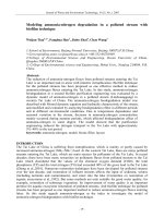
This section begins with an
assembly called
slide_plate.
First, the overender
shaft part will be edited
because it is not long
enough for the current
configuration. Then a new
part called motor_mount
will be created in the
context of the assembly. Features that use geometry from the assembly,
mainly the motor part, will be created. Relationships will be
established between the parts when the new features are created.
Stages in the
Process
The major stages in the process are listed below:
Q Adding new parts into an assembly
When you add a new component part to an assembly, you have to give
it a name and select a plane (or planar face). The name is used as the
part name while the plane orients the Front reference plane of the
new part.
Q Building parts in an assembly
As the new part is created, the selected plane/face becomes the active
sketch and the part is in Edit Part mode. The part is created using
standard methods and references to other geometry in the assembly.
Q Creating in-context features
When you reference geometry in other parts while creating a feature,
you are creating what is called an in-context feature. For example,
referencing the edge of a shaft when making its mating hole in another
part creates a relationship between the shaft and the hole. A change to
the diameter of the shaft would cause a corresponding change to the
diameter of the hole.
Alternatively, you can change the setting Do not create references
external to the model
in Tools, Options, External References, and
the new feature or part will not be created with any external references.
Converted geometry is simply duplicated in this case, with no
constraint. No dimensions or relations to other components or assembly
geometry can be added.
Q Hole Series
A Hole Series is a special kind of Hole Wizard hole that is created at
the assembly level and automatically creates in-context holes in the
referenced components.
Lesson 1 SolidWorks 2005 Training Manual
Top-Down Assembly Modeling
10 In-context Features
Prerelea
s
e
D
o
no
t
co
p
y
or
di
st
r
ib
ut
e
Q Assembly patterning
Components can be patterned in the assembly using existing patterns in
parts or in a linear or circular pattern unique to the assembly.
Q Breaking external references
In-context parts and features create many external references. To break
these references and keep the part intact, several techniques are used.
In-context
Features
In-context Features are used to create geometry in the active part by
sketching on, converting, offsetting or dimensioning to, geometry in
other component parts. The feature that is created is called an
In-
context Feature
, a feature with external references. In this example,
the overender shaft will be redesigned to fit the requirements of
the assembly.
Design Intent:
In-context Feature
The design intent of this feature is listed
below.
Q The new feature of the overender
shaft is to be an extension of the
current shaft.
Q The new feature must be coradial with
the coupling part with a mating
“D” keyway.
Q The shaft must have at least 0.625 inches of engagement depth in
the coupling.
1 Open the existing assembly slide_plate.
It contains several components of a rotational shaft assembly.
2 Section View.
Use the Section
View
tool with the
Right plane to
section the
assembly. The
plane can be
moved, but its
default location
cuts the model
perfectly in half.
SolidWorks 2005 Training Manual Lesson 1
Top-Down Assembly Modeling
In-context Features 11
Prerelea
s
e
D
o
no
t
co
p
y
or
di
st
r
ib
ut
e
More than one
plane can be used
to generate the
section view. The
illustrations at right
used a combination
of 2 planes.
Edit Part While you are in an assembly, you can switch between editing the
assembly — adding mate relations, inserting components, etc. — and
editing a specific part. Editing a part while in the context of an
assembly allows you to take advantage of geometry and dimensions of
other components while creating matching or related features. Using
geometry outside the part creates External References and In-context
Features
.
Two commands, Edit Part and Edit Assembly, are used to switch back
and forth between editing one component in an assembly and editing
the assembly itself. When you are in edit part mode, you have access to
all the commands and functionality the part modeling portion of
SolidWorks. Plus, you have access to other geometry in the assembly.
In this example, we will use Edit Part to make changes to the
overender shaft part while in the context of an assembly.
Introducing:
Edit Part and
Edit Assembly
Edit Part/Edit Assembly is used to switch between editing a part, and
editing the assembly itself. The right-mouse menu will display the
proper command.
Where to Find It Select the part you wish to edit. Then:
Q Click Edit, Part.
Q Or, from the right-mouse menu, select Edit Part or Edit Assembly.
Q Or, from the Assembly toolbar, click the tool.
3 Hide the motor.
Before you begin, Hide the motor part. This will avoid referencing any
of its geometry by accident.
Lesson 1 SolidWorks 2005 Training Manual
Top-Down Assembly Modeling
12 In-context Features
Prerelea
s
e
D
o
no
t
co
p
y
or
di
st
r
ib
ut
e
4Edit Part.
Select the component overender shaft and click the Edit Part
tool. The component and its representation in the FeatureManager
change color. The color used is the current Edit Part in Assembly
color, which by default is royal blue, but for these examples has been
set to pink in Options, System Options, Colors, System colors.
Note also that Use specified colors when editing parts in assembly
should also be checked.
Tip The tool is a toggle. It switches you between Edit Part mode and
Edit Assembly mode. It also acts as a visual indicator of which mode
you are in. It is depressed when you are in Edit Part mode.
Note The ToolTip on the tool says Edit Component. In an assembly,
both parts and sub-assemblies are considered components. To see the
edit part color click
Use specified colors when editing parts in
assemblies
found under Tools, Options, System Options, Colors.
Other indicators that you are in Edit Part mode are the status bar which
reads Editing Part, and the window banner which looks like this:
.
Appearance of
Components While
Editing
When you edit a part in the context of the assembly, the color of the
component you edit depends on a setting in Tools, Options, Colors. If
set to Use specified colors when editing parts in assemblies, the
edited part will be opaque pink by default. This color can be
customized in the System colors area on the same tab. The appearance
of the other components depends on the assembly transparency settings
you choose.
Introducing
Change Assembly
Transparency
The transparency of components that are not being edited can be set to
one of three conditions:
Q Opaque assembly. All components become opaque gray, except
for the component you are editing, which becomes opaque pink.
Q Maintain assembly transparency. All components maintain
whatever their current transparency is, except for the one you are
editing, which becomes opaque pink.
Q Force assembly transparency. All components become
transparent except the one you are editing, which becomes opaque
pink.
Where to Find It Q From the menu click Tools, Options, System Options, Display/
Selection, Assembly transparency for in context edit
.
Q Or, from the Assembly toolbar, click the tool.
SolidWorks 2005 Training Manual Lesson 1
Top-Down Assembly Modeling
In-context Features 13
Prerelea
s
e
D
o
no
t
co
p
y
or
di
st
r
ib
ut
e
Note Use the slider to adjust the transparency level for Force assembly
transparency
. When you move the slider to the right, the components
become more transparent.
How Transparency
Affects Selecting
Geometry
As you move the cursor over components in the graphics area, various
geometry such as faces, and edges highlight. Clicking the left mouse
button selects the highlighted geometry.
Usually the cursor selects whichever geometry is in front. However, in
an assembly with transparent components, the cursor selects geometry
on the opaque components first, even if transparent components are in
front.
Note For purposes of selection, transparent means more than 10 percent
transparent. Components with less than 10 percent transparency are
considered opaque.
There are some techniques you can use to control how you select
geometry:
Q Click Change Assembly Transparency, and select Opaque. Now
all geometry is treated the same and the cursor selects whichever
face is in front.
Q Press Shift to select geometry on a transparent component when
there is an opaque component behind it.
Q Press Tab to select the part you are editing through an opaque
component.
Q Use Select Other to select faces that are obscured by other faces.
The Force assembly transparency option will be used in this
example.
5 Sketch plane.
The sketch plane used for the mating
shaft extension is the existing end face of
the overender shaft. Select it and
click Insert Sketch.
Lesson 1 SolidWorks 2005 Training Manual
Top-Down Assembly Modeling
14 In-context Features
Prerelea
s
e
D
o
no
t
co
p
y
or
di
st
r
ib
ut
e
6 Convert Entities.
Select the circular edge of the bore of
the coupling part, then click
Convert Entities .
This transfers the geometry of the
selected entity to the new sketch, and
establishes a relationship between
them, so that changes to the bore will
be passed on to this new sketch.
Note The arc is black (fully defined). As indicated earlier, if Do not create
references external to the model
is selected in options, there will be
no relationship established between the existing geometry of the
coupling and the new entity. The arc in this case would be blue
(under defined).
7 Reorient.
Change the display to be Normal To the
sketch plane. This will make it easier to
construct the remainder of the profile.
Note The Section View command can now be turned off.
8 Complete sketch.
Sketch a vertical line between the two
endpoints of the arc.
Note You could also preselect the edge and Offset the keyway edge entity to
achieve the same result. However, selecting the edge may be difficult
SolidWorks 2005 Training Manual Lesson 1
Top-Down Assembly Modeling
In-context Features 15
Prerelea
s
e
D
o
no
t
co
p
y
or
di
st
r
ib
ut
e
without using selection filters.
9 Extrude offset from
surface.
Select the Extrude tool,
and set the end
condition to Offset
From Surface
. Use
Select Other to select
the end face of the
coupling. Set the
offset distance to 0.75”.
Be sure Merge result is
checked so that one
body is created. Also
add 1
o
of Draft.
Click OK.
Tip Features can have different sketch planes and end conditions for
different configurations. This could be used to create in-context and
stand-alone versions of the same feature. Refer to Lesson 10:
Configurations of Parts in the SolidWorks Essentials: Parts and
Assemblies manual for more information.
10 Hide component.
Return to Edit Assembly mode
by clicking the Edit
Component
tool.
Select the coupling part and
click the Hide Component
tool, or right-click the
component and choose Hide.
The FeatureManager design
tree lists the new feature as
Extrude1 ->. The arrow
symbol, ->, indicates one or
more external references.
The external references created between components are listed as
features at the bottom of the FeatureManager design tree
. They are called
Update Holders.
New in-context
feature
Lesson 1 SolidWorks 2005 Training Manual
Top-Down Assembly Modeling
16 In-context Features
Prerelea
s
e
D
o
no
t
co
p
y
or
di
st
r
ib
ut
e
Tip The display of the Update Holders can be toggled on and off. While in
Edit Assembly mode, right-click the top-level assembly icon , and
select
Hide Update Holders from the shortcut menu.
11 Open part.
Right-click the overender shaft, and select Open Part from the
shortcut menu.
12 Chamfer.
Add a Chamfer, 0.1” x 45
o
, to the base of
the flat face, and to the top edges of the
boss.
13 Fillet.
Add a Face fillet, using the barrel of the
new boss and the original end face as
shown. Use the edge as a hold line.
14 Return to the assembly.
Press Ctrl+Tab to switch from the part document back to the assembly
document.
15 Update.
When the assembly window becomes active, the changes to the over-
ender shaft are detected and SolidWorks asks: “Models contained
within the assembly have changed. Would you like to rebuild the
assembly now?”. Click
Yes.
Tip Generally, if the changes are minor and the assembly is small, click
Yes. If there are numerous changes to be made, and if the assembly is
very large, you should click
No and defer rebuilding until all the
changes are completed.
Hold line
SolidWorks 2005 Training Manual Lesson 1
Top-Down Assembly Modeling
Propagating Changes 17
Prerelea
s
e
D
o
no
t
co
p
y
or
di
st
r
ib
ut
e
16 Show the coupling.
Use Show Component to see the
coupling and motor
components again.
Turn on the Section View again.
Propagating
Changes
Automatically propagating changes is one of the strongest qualities of
the in-context feature. In the next portion of this lesson, we will explore
how a change to the size of the shaft of the motor will propagate
through the assembly, and force a change in the coupling (due to its
pre-existing in-context reference) and in turn the overender
shaft.We will also look at those conditions when a change might not
propagate and what to do about it.
17 Open motor.
Right-click on the motor and select Open
Part
from the right mouse menu. This will
open the part document separate from the
assembly.
18 Edit Sketch1.
Double-click Sketch1 under the
Base-Revolve feature to see its
dimensions.
Note The motor part model is a relatively simple geometric representation
of the shape and size of the part. It is not intended to be a detailed
model. This is a typical practice with OEM components.