Tài liệu PERFORMANCE AND SAFETY STUDIES FOR MULTI-APPLICATION, SMALL, LIGHT WATER REACTOR ( MASLWR) pptx
Bạn đang xem bản rút gọn của tài liệu. Xem và tải ngay bản đầy đủ của tài liệu tại đây (519.79 KB, 21 trang )
1
PERFORMANCE AND SAFETY STUDIES FOR MULTI-
APPLICATION, SMALL, LIGHT WATER REACTOR (MASLWR)
1
James E. Fisher, S. Michael Modro, Kevan D. Weaver
Idaho National Engineering and Environmental Laboratory
Jose Reyes, John Groome
Oregon State University
Pierre Babka
Nexant, Inc.
SUMMARY
The Multi-Application, Small, Light Water Reactor (MASLWR) is a modular natural circulation design
with the reactor core and steam generator contained in a single vessel, located within a cylindrical
containment, which is in turn, submerged in a pool of water. The containment itself is partially filled with
water, to serve as a blowdown suppression pool and as a source of core makeup liquid. The core is
composed of standard PWR assemblies with an active fuel height of approximately 1 m and consists of
cylindrical fuel pins containing UO2 or THO2-UO2 pellets, enriched to < 20%. The steam generator is a
helical-tube, once-through heat exchanger, consisting of approximately 1000 tubes arranged in an upwardly
spiraling pattern. Water heated by the core flows upward through a central riser and is cooled as it flows
downward through an annular space that contains the heat exchanger spiral, and returns into the bottom of
the core. Cold feedwater enters the steam generator tubes at the bottom and slightly superheated steam is
collected at the top. Steady-state characterization studies were conducted to determine operational
parameters and demonstrate system stability. Results of these studies show that the system will operate in a
stable state at a thermal power level of 150 MW at a pressure of approximately 10 MPa, while supplying
steam at 1.52 MPa (220 psia) superheated by 10 K.
Transient safety studies were done for loss-of-coolant accidents within the containment and other accidents.
The results defined the required configuration and sizes of the venting, automatic depressurization, and
sump makeup lines. Redundant sets of 3-inch upper containment automatic depressurization system (ADS)
vent lines, and submerged 8-inch ADS blowdown valves and 4-inch sump makeup lines are required to
ensure adequate core cooling and decay heat removal and to prevent containment overpressure. The results
show that the reactor core can be provided with a stable cooling source adequate to remove decay heat
without significant cladding heatup under all credible scenarios. Further, the heat rejected through the
containment wall to the surrounding pool of water will be greater than the amount of decay heat produced
by the reactor core.
INTRODUCTION
The MASLWR (Multi-Application, Small, Light Water Reactor) project is being conducted under the
auspices of the NERI (Nuclear Energy Research Initiative) program of the U.S. DOE (Department of
Energy). The purpose of the project is to create a reactor plant concept, including design, safety, and
economic attributes, and to test its technical feasibility in an integral test facility. The concept consists of a
small, natural circulation light water reactor design, which is primarily to be used for electric power
generation, but is flexible enough to be used for process heat with deployment in a variety of locations.
DESIGN DESCRIPTION
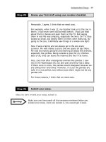
The MASLWR is a modular design and consists of an integral reactor and steam generator, enclosed in a
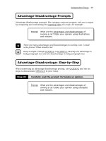
vessel that is located within a steel cylindrical containment. Figure 1 illustrates the concept. The entire
module is 4.3 m (14 ft) in diameter and 18.3 m (60 ft) long. The free space within the containment is
partially occupied with water, and the integral vessel is submerged in liquid to a level just below the
feedwater nozzles. A sump makeup system connects the containment with the lower vessel region, and an
automatic depressurization system (ADS) provides pressure suppression and primary system venting,
1
Work supported by the U.S. Department of Energy, Office of Nuclear Energy, Science, and Technology, under DOE Idaho
Operations Office Contract DE-AC07-99ID13727.
2
thereby permitting makeup liquid from the containment to enter the vessel in the event of an accident
scenario. The containment is submerged in a pool of water. Cooling of the containment during normal and
abnormal conditions is accomplished by steam condensation on and heat conduction through the
containment steel walls to this pool of water. Heat from the pool is removed through a closed loop
circulating system and rejected into the atmosphere in a cooling tower designed to maintain a pool
temperature below 311K (100 F). For the most severe postulated accident, the volume of water in the cavity
provides a passive ultimate heat sink for 3 or more days, permitting time for restoration of the active heat
removal systems.
Steam
Feedwater
Sump
makeup
valve
Steam
Water
Containment
Reactor pressure vessel
Water
Core
Depressurization
valve
Steam generator
tube bundle
Gen
Condenser
Feedwater
pump
Turbine generator
Vent
valve
Figure 1. Simplified diagram of MASLWR heat cycle.
The NSSS (Nuclear Steam Supply System) is a “self-contained” assembly of reactor core and heat
exchanger (steam generator) within a single pressure vessel . The nuclear core is located in the lower part
of the vessel, with the steam generator above it. To effectively use natural circulation, the core is connected
directly to the space above the heat exchanger via a large-diameter tube, or riser, which is an upper
extension of the core barrel. The primary liquid flow path is upward through the riser, then downward
around the heat exchanger tubes, returning to the bottom of the core via an annular space.
The steam generator is a helical-tube, once-through heat exchanger, located above the reactor. The heat
exchanger consists of approximately 1000 tubes, arranged in an upwardly spiraling pattern. Cold feedwater
enters the tubes at the bottom, and slightly superheated steam is collected at the top. This steam drives a
turbine generator to produce power.
The core consists of standard PWR assemblies, with an active fuel height of approximately 1 m (3.3 ft), and
an overall height to diameter (H/D) ratio for of approximately 1. The fuel consists of cylindrical pins with a
cladding outer diameter of 9.5 mm (0.37 in), and a pitch-to-diameter ratio (P/D) of 1.33. The fuel pellets
are UO2 or ThO2- UO2, enriched to <20% U-235 (in the uranium). Although the use of current LWR
technology is employed in the current development, further enhancements to better meet Generation IV
goals will be explored; particularly the efficient use of uranium (fuel) resources by optimizing the core
design, fuel material, and fuel cycle.
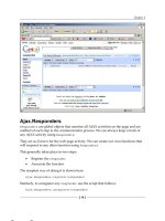
RELAP5 MODEL
3
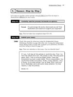
The RELAP5 model of the MASLWR system is shown in Figure 2. Annulus component 101 represents the
annular downcomer region surrounding the core barrel, 111 is the lower plenum and 115 is the reactor core.
Components 165 through 210 comprise the riser section, and 215 and 216 are the upper plenum region.
4
3
2
1
5
165
200
210
-1
210
-2
210
-3
210
-4
210
-5
210
-6
210
-7
215
216
230
245
237
217
ADS Vent
ADS Break
233
ADS
4
3
2
1
5
500
510
236
232
221
221 601
1
10
20
4
3
2
1
5
560
611
615
1
28
10
20
555
550
565
570
Containment
Liquid
Pool
115
Core
Riser
Steam
Generator
101
1
2
3
4
503
505
Sump
Makeup
111
630
520
-1
520
-2
602
635
Figure 2. RELAP5 model.
4
Component 221 consists of a RELAP5 pipe containing 30 volumes and represents the shell side of the
steam generator. Components 230 and 245 represent the annular space outside the lower riser section.
Heat structures are used to represent metal masses within the system, and are connected to the fluid
volumes using the RELAP5 convective heat transfer package. The core barrel represents the conduction
path between the downcomer and the core and the riser pipe models the conduction path between the hot
and cold sides of the primary system. The vessel wall is not explicitly modeled; the vessel-has an adiabatic
boundary where it meets the containment fluid. Component 601 consists of a RELAP5 pipe containing 28
volumes that represent the secondary (tube side) of the steam generator. Components 615 and 611 are the
feedwater flow boundary condition and 602, 630, and 635 model the steam system (630 represents the
turbine throttle valve). Heat structures representing the steam generator tubes model the conduction path
between the primary and secondary sides of the steam generator. The ADS vent system is represented by
valve 217, and the ADS blowdown system is 232-237 (including break piping). The Sump makeup system
consists of volume 503 and valve 505. The containment is divided into two annular regions: component
500 represents the inside space adjacent to the vessel, and 510 represents the outer region bounded by the
containment wall. Junctions 520-1 and 520-2 connect the lowermost and uppermost volumes, respectively,
of the containment annular regions. Component 560 represents the liquid pool surrounding the
containment. Heat structures representing the containment wall model the conduction path between the
containment outer annulus and this pool.
Neutron physics calculations were performed to obtain reactivity feedback coefficients for the one-
dimensional neutron kinetics model. The results of these calculations yielded the following coefficients:
• Doppler Temperature Coefficient = -0.005132 $/K
• Moderator Temperature Coefficient = 41.0049 $/gm/cm
3
.
RESULTS
Steady-state and transient performance data were characterized using the RELAP5 model. Two versions of
the steam generator tube bundle were used for the RELAP5 results. The transient cases were performed
with an input file that represents an early steam generator tube bundle configuration. In this early version,
the steam generator tube bundle consisted of 480 tubes, with outside diameter of 0.0254 m (1 inches),
inside diameter of 0.0203 m (0.8 inches), arranged in five helical rotations with a total length of 23.7 m
(77.8 ft).
After completion of the model used to perform the transient analysis the steam generator tube bundle
specification was modified. The revised bundle configuration consisted of 1012 tubes, with an outside
diameter of 0.0159 m (0.625 inches), an inside diameter of 0.0126 m (0.495 inches) arranged in four helical
rotations and having a total length of 22.7 m (74.6 ft). The steady-state characterization studies were
performed to establish operating conditions for this configuration. Table 1 summarizes the dimensional
parameters of the steam generator data used in the RELAP5 calculations.
Steady-State Operation
RELAP5 was used to establish the conditions at which the system will operate, given the required boundary
conditions. The NSSS is required to deliver steam at approximately 1.52 MPa (220 psia) pressure and
superheated by 10
o
K to a turbine-generator rated at approximately 35 MWe. The thermal efficiency for
operation at this steam temperature is estimated to be approximately 23%. Therefore, the NSSS must
supply approximately 150 MWt. The primary side conditions are established by the heat rejected by the
steam generator tubes, the overall heat transfer coefficient, the frictional losses, and the density differential
between the hot and cold thermal centers. The heat load determines the enthalpy that must be added by the
core, the heat transfer coefficient establishes the primary system temperature at the outlet of the steam
generator, and the frictional losses and the density differential between thermal centers determines the
primary system mass flowrate. During steady-state operation the reactor core operated in subcooled
nucleate boiling, and the two-phase mixture in the core and the riser region was in the bubbly flow regime.
Table 2 shows the performance characteristics of the model in steady-state operation.
5
Table 1. Steam generator dimensional data for RELAP5 models.
Dimension Early RELAP5 Model Current Design
(SI) (British) (SI) (British)
Tube OD
(m or in)
0.0254 1 0.0159 0.625
Tube ID
(m or in)
0.0203 0.8 0.0126 0.495
Number of tubes 480 1012
Rotations 5 4
Pitch-to-diameter ratio (horizontal) 1.8 1.8
Pitch-to-diameter ratio (vertical) 1.5 1.5
Tube Length 23.7 77.8 22.7 74.6
Length-to-Diameter Ratio 1166 1808
Secondary Flow Area
(m^2 or ft^2)
0.156 1.676 0.126 1.354
Primary Heat Transfer Area
(m^2 or ft^2)
907.8 9771.1 1148.2 12359.4
Secondary Heat Transfer Area
(m^2 or ft^2))
726.2 7816.9 909.6 9791.0
Distance Between Thermal Centers
(m or ft)
9.2 30.2 9.2 30.2
Table 2. MASLWR steady-state performance characteristics.
Reactor power (MW) 150
Steam Pressure (MPa) 1.52
Outlet Quality 1.0
Steam Temperature (K) 480.1
Saturation temperature (K) 472.0
Feedwater Temperature (K) 410.0
Feedwater Flowrate (kg/s) 67.0
Primary pressure (MPa) 9.6
Primary mass flow rate (kg/s) 432
Reactor inlet temperature (K) 499
Reactor outlet temperature (K) 566
Saturation temperature (K) 580.8
Reactor outlet void fraction 0.126
Transient Performance
As noted, the transient performance characterization was performed with an input file containing an early
steam generator tube bundle configuration, and therefore the following results are preliminary. Because of
budget constraints at the time the transient analysis was performed there were insufficient resources
available to make the updates to the tube bundle, obtain new steady-state conditions, and repeat the
transient calculations. However, as is shown in Table 1. the important parameters of the steam generator
related to thermal performance are conservative, primarily because the early tube bundle had smaller
surface area than the current design.
The performance of the design was verified and optimized during accident studies. The objectives of these
studies were the following:
• Demonstrate adequate cooling of the reactor core
• Demonstrate the mechanism and adequacy of heat removal to the ultimate heat sink
6
• Determine the size, location, and other requirements for the ADS and sump makeup systems
The bases for determining the requirements for the ADS and sump makeup systems were preventing core
uncovery and excessive containment pressure. The criterion for core uncovery was that no significant core
heatup should occur. The criterion for containment pressure was a maximum transient value of 2.8 MPa
(400 psia), based on controlling the cost of the containment vessel.
Break size and location considerations were the following.
1. It was assumed that a rupture of the vessel containing the reactor core and steam generator is a non-
credible event.
2. The minimum required piping penetrations for the system are assumed to include:
• charging/letdown system line
• vent line used to remove noncondensible gases and possibly provide pressure regulation
• ADS blowdown line
• sump makeup line from the containment liquid pool into the lower region of the downcomer
3. It is assumed that a break of a vent line represents a limiting above-waterline break scenario. The
three-inch break should conservatively represent the size of the vent line.
4. A sump line or ADS blowdown line break represents the limiting below-waterline break scenario. The
ADS line (8 inches) is larger than the sump line (4 inches) but the nozzle is located higher in the
downcomer. The charging/letdown system can share a penetration with the sump makeup line, and
therefore does not need to be considered separately.
The success of the transient characterization depends upon the performance of the Emergency Core Coolant
Systems, which includes the ADS vent and blowdown lines, the sump makeup system, and the
containment. The important requirements regarding the performance of these systems are the following.
• The reactor core can be provided with a stable cooling source adequate to remove decay heat without
significant cladding heatup under all credible scenarios.
• During accident conditions a recirculation flow path must be established between the vessel and the
containment via the ADS and sump makeup systems. This recirculation path must provide sufficient
capability for removal of decay heat from the vessel.
• The heat rejected through the containment wall to the surrounding pool of water must exceed the
amount of decay heat produced by the reactor core.
For certain break scenarios, scram signals based on RCS pressure and level decrease and containment
pressure increase responses do not provide adequate scram protection. Therefore, a preemptive scram
signal is required. In these cases, a scram on low downcomer flow was shown to be sufficiently fast to
provide core protection. However, it is likely that a reactivity, or power rate, scram would be easier and
more reliable to implement for the preemptive scram.
The trip system consists of reactor scram signals, turbine and feedwater trip signals, and ADS actuation.
Table 3 lists the trip system signals assumed to be available.
The following scenarios were simulated:
• 3-inch break
• Inadvertent ADS blowdown valve opening
• ADS blowdown line break (one side) with subsequent ADS actuation (other side)
• ADS blowdown valve opening, no sump makeup capability
• Main steam line break
7
Table 3. Trip system for transient analysis.
Reactor Scram
Signal setpoint time delay
Low upper plenum pressure 8.5 MPa 0.7 s
Low upper plenum level 0.5 m 1.5 s
Turbine trip tripped 0.0 s
Manual scram operator 0.0 s
Low steam header pressure 1.2 MPa 0.5 s
Automatic depressurization system open 0.2 s
Low Downcomer flow 350 kg/s 0.5 s
Turbine Trip
Signal setpoint time delay
Low SG Tube Mass 300 kg 0.0 s
Manual Trip operator 1.0 s
Reactor scram scram 2.5 sec
Feedwater Trip
Signal setpoint time delay
Turbine trip tripped 2.0 s
Low steam header pressure 1.2 MPa 0.5 s
Manual trip operator 0.0 s
Automatic Depressurization System Actuation
Signal setpoint time delay
High containment pressure 0.5 MPa 0.0 s
High upper plenum pressure (MPa) 12 MPa 0.0 s
Low upper plenum pressure 8.5 MPa 0.7 s
Low upper plenum level 0.5 m 0.5 s
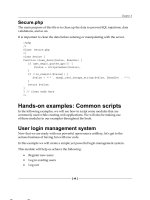
The configuration of the MASLWR design shown in Figure 3 depicts the reference, final configuration of
the Emergency Core Coolant Systems. The ADS high containment vent valve nozzle is located at the top
of the vessel, and vents the steam and gas space. This nozzle is also assumed to supply the normal
noncondensible gas vent. The ADS submerged vent line nozzle is located in the downcomer region of the
vessel below the feedwater nozzle, and is also below the waterline of the containment. The sump makeup
valves are also located in the downcomer region, above the level of the top of the reactor core. Check
valves in the sump makeup lines prevent flow from the vessel to the containment
Three-Inch Line Break Scenarios
Three-inch line break scenarios were analyzed to demonstrate that adequate core cooling would occur and
that sufficient heat would be rejected to the liquid pool at the containment wall. The break is assumed to be
at the nozzle of a high vent that discharges directly into the upper containment. It is assumed that a vent
line must be present at the top of the vessel to remove noncondensible gases, and possibly to be available
for pressure control purposes. It is further assumed that the nozzle penetration for this vent line will also
serve the ADS high containment vent line that discharges to the upper containment. This line is assumed to
be 3 inches in diameter.
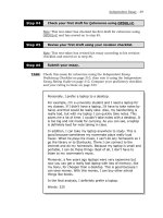
ADS Blowdown Line Vented to Upper Containment.
In this scenario, the ADS blowdown line was assumed to be a single line, 8 inches in diameter, and vented
to the upper containment. The sump makeup system was also assumed to be present and operational.
Primary and containment pressures are shown in Figure 4. As shown, maximum containment pressure was
3.4 MPa (500 psia) at 200 seconds. In this transient, the ADS blowdown was actuated at 8 m collapsed
8
liquid level in the vessel
(approximately 3.5 m below the
nominal operating value).
Therefore, the maximum
containment pressure was solely
due to discharge from the 3-inch
break. The issue of reducing the
maximum containment pressure to
< 250 psia will be addressed in the
next section.
Figure 5 is a comparison of
integrated flow rates of “break plus
ADS discharge” and “sump
makeup”. Notice that the value of
the “break plus ADS discharge
flow” history was offset vertically
to make it easier to compare its
slope to that of the integrated
makeup flow. The slopes of the
two curves became equal late in the
transient (after about 1400
seconds), thereby demonstrating
that the makeup liquid flowrate was
equal to the vessel mass loss.
Therefore, steam vented from the
top of the vessel through the break
and the ADS blowdown line was
replaced by an equal mass of
makeup liquid from the
containment liquid pool, thus
forming a recirculation path. This
recirculation path provided the
mechanism for removal of decay
heat from the vessel.
Figure 6 is a comparison of core
decay heat and heat rejected at the
containment wall, and shots that
after approximately 30 seconds (20
seconds after break initiation) the
wall heat transfer exceeded core
decay heat. This result
demonstrates that the heat transfer
rate from the containment through
the containment wall to the
surrounding pool of water was
sufficient to reject the amount of
decay heat produced by the reactor
core. Figure 7 shows fuel cladding
surface temperature responses.
There were no excursions of
temperature observed during the scenario. Therefore, the core was adequately supplied with cooling flow
throughout the transient.
Top of
Core
Bottom
of Core
Ste a m
& NC Gas
Containment
Wa te r
Sump
Ma k e u p
Va l ve s (2)
Automatic
De pre ssuri za ti on
Submerged Vent
Va l ve s (2)
Fe e d w a te r
No zzle
Ste a m
No zzle
Core Cross-section
Auto m a ti c
De pre ssuriza tion
High Conta inment
Ve nt Va l ve s (2)
Figure 3. MASLWR Containment and Internal Components.
9
ADS Blowdown Line Submerged in Containment Pool.
Additional three-inch break cases were simulated, with the ADS blowdown line discharge submerged in the
containment liquid. The configuration of these cases is as shown in Figure 3. The purpose was to define
the minimum size piping for the submerged ADS vent line that prevents containment overpressure from
occurring during the broken upper containment vent line scenario. Two cases were run, with the ADS
blowdown piping nominal diameters of 6 inches and 8 inches. For these cases it was assumed that one of
the two ADS blowdown valves failed to open. The response of system pressure for the two cases is shown
in Figure 8. Maximum pressure for the 6-inch line case was 2.2 MPa (320 psia) and for the 8-inch line case
was 1.2 MPa (170 psia). This sensitivity study determined that the minimum nominal ADS blowdown line
size of 8 inches is required for a submerged ADS blowdown to prevent pressurizing the containment above
250 psia.
Inadvertent ADS Blowdown Line Opening with Submerged Discharge
ADS High Containment Vent Disabled
Two inadvertent ADS blowdown line opening scenarios were performed with the ADS blowdown line
nozzle connected to the top of the RCS vessel, with the discharge point approximately 8 m below the
waterline of the containment. For these calculation, opening of a single 6-inch-diameter ADS blowdown
line was assumed. In both calculations, the sump makeup lines were as shown in the reference
configuration (shown in Figure 3). A single ADS blowdown line valve was opened. In the first calculation,
the ADS high containment vent was disabled. Figure 9 shows the pressure responses of the vessel and
containment during this transient. The continuous discharge of steam from the vessel caused vessel
pressure to exceed containment pressure by an amount corresponding to the height of the water column
displaced by the steam in the submerged section of the ADS blowdown line. This vessel-to-containment
differential pressure prevented water from entering via the containment sump makeup valve.
ADS High Containment Vent Operable
The second calculation was performed with the (3-inch) ADS high containment vent path operable. The
ADS high vent was opened on a combination of low vessel level and high differential pressure between the
vessel and the containment when vessel pressure had decreased to 500 kPa. Figure 10 shows containment
and vessel pressures for this case. Note that the ADS high vent was adequate to exhaust the steam to the
containment above the waterline and allow the submerged ADS blowdown line to refill with water, thereby
permitting liquid to enter the vessel via the sump makeup line. Figure 11 shows the mass flow rate through
the sump makeup valve with and without the vent. The flow rate was negligible for the case without the
ADS high vent, and 9000 kg/s for the case with this vent opened. Figure 12 shows the response of vessel
collapsed liquid level for the cases without and with the ADS high containment vent path. The case with
the ADS high vent showed immediate vessel level recovery to a collapsed liquid level of > 7 m, which is
approximately the elevation of the feedwater nozzle. Without this vent, level decreased continuously until
the transient was terminated at 2000 seconds. These results demonstrated the requirement for the ADS
high containment vent path. If this vent path was not available, the gravity head caused by venting steam
through the ADS submerged blowdown line prevented the entrance of sump makeup water and the
subsequent recovery of vessel inventory.
Nozzle Breaks Below the Containment Waterline
The results of the 3-inch break scenarios imply that a rupture of the ADS blowdown line piping between
the vessel and the valve, in a region that is not submerged, will result in containment pressures beyond
acceptable limits. One option is to run the ADS blowdown line piping inside the vessel and locate the
vessel penetration below the waterline. However, it is more straightforward to locate the ADS blowdown
line nozzle itself below the waterline, because it avoids interference with the vessel internals. Therefore,
cases were run with the ADS blowdown line nozzle located below the surface of the containment liquid
pool. This configuration is the same as is shown in Figure 3.
Early Departure from Nucleate Boiling.
The first major issue with postulated breaks low in the vessel on the cold side is the potential for core flow
stagnation and cladding heatup early in the transient before the fuel temperature profile has collapsed. This
effect is sensitive both to break size and to break location. The two locations of concern are the ADS
10
blowdown line nozzle and the sump makeup line nozzle. The ADS blowdown line nozzle is located
relatively high on the downcomer side, and the nozzle diameter is 6 inches. This sump makeup line nozzle
(in the RELAP5 model) is located in the vessel downcomer at the level of the upper third of the reactor
core, and the nozzle diameter is 4 inches. Therefore, it is not clear which break is most limiting, and both
breaks were analyzed. These breaks were analyzed assuming that a reactor scram occurred quickly enough
to avoid a power excursion due to positive reactivity insertion. This point will be discussed in the next
section.
Figure 13 shows fuel cladding surface transient temperature response for the ADS blowdown line nozzle
break. As shown, a small heatup was calculated (maximum cladding surface temperature was 650 K at
11.5 seconds. Additionally, a sump line break scenario was simulated. Figure 14 shows the fuel cladding
surface temperature for the sump line nozzle break. The peak calculated temperature is slightly higher than
for the ADS blowdown line break, about 675 K. However, the maximum temperatures in both cases are
well below regulatory limits, so the results are considered acceptable.
Reactivity Insertion Due to Early Void Collapse.
A second issue with submerged breaks is that the responses of decreasing RCS pressure and level and
increasing containment pressure are not fast enough to provide an early scram signal. Because operation is
assumed to occur with the core in nucleate boiling (approximately 15% core outlet void fraction), a rapid
void collapse, which may lead to a significant power excursion, must be avoided while the reactor is at
power. Additionally, in this design, the reactor scram insertion time must be shorter than the thermal-
hydraulic response. Figure 15 shows density in the center and upper core regions for the inadvertent ADS
opening transient. As shown, initial density in the upper core region, for example, was 597 kg/m
3
. When
the ADS blowdown line nozzle break was opened, there was an initial decrease in density, but 2 seconds
after the transient was initiated, density had increased to 640 kg/m
3
. This net increase in density was worth
approximately 1$. For the submerged breaks, for which RCS pressure and level decrease and containment
pressure increase responses are not fast enough to provide an early scram signal, a preemptive scram signal
is required. A reactivity, or power rate, signal would be appropriate to use for this preemptive scram.
Minimum Size of ADS High Containment Vent Valve.
A sensitivity study was performed to determine the minimum size required for the ADS high containment
vent that would ensure vessel inventory recovery in the event of an inadvertent ADS blowdown line
opening. The configuration used for this sensitivity study was the reference configuration shown in Figure
3. Inadvertent ADS blowdown line opening scenarios were conducted with high containment vent
diameters of one, two, and three inches. Figure 16 shows the vessel collapsed liquid level responses for the
three cases. Note that level recovery occurred only in the three-inch case. This study sets the minimum
size of the ADS containment high vent, in the present configuration, to three inches nominal diameter.
Inadvertent ADS Blowdown Valve Opening with No Makeup Flow.
A potential means for heat transfer between the primary vessel and the containment being considered is use
of an “intelligent” material that behaves as an insulator at low temperatures and as a conductor at high
temperatures. This material would be applied to the outer surface of the vessel in the region that is in
contact with the containment water pool, and would act as an insulator between the primary system and the
containment during normal operation. During accident conditions, heatup of the primary coolant would
cause this material to change properties and become a conductor that would provide a path for cooling the
primary system. Such an effective heat transfer mechanism may obviate the need for a sump makeup
valve. Therefore, a calculation was performed to evaluate the effectiveness of conduction/ convection
through the vessel wall as a method of heat transfer between the primary system and the containment. It
was assumed that the insulating material became a perfect conductor, and that the outer vessel surface was
in direct thermal contact with the containment pool. With this assumption in the model, the inadvertent
ADS blowdown valve opening transient was repeated. The sump makeup flow path was disabled, and no
ADS high containment vent path was available.
Figure 17 shows the vessel collapsed liquid level response during the transient. As shown, collapsed liquid
level continued to decrease throughout the transient, because of the continued boiloff of the core and the
11
lack of makeup liquid. At no time did the core become sufficiently cooled that fluid reentered the vessel
via the broken ADS line to replenish that which was being boiled off. At approximately 5000 seconds,
when the collapsed liquid level had fallen to about 1.2 m, core heatup began, as shown in Figure 18. This
heatup continued, unmitigated, because sufficient cooling water was not available within the vessel. This
study demonstrates that conduction through the vessel wall is by itself not a sufficient mechanism for heat
removal in the present design. In order to effectively remove the core decay heat, a circulation path must
be established so that the vessel inventory loss due to steam boiloff is replaced by liquid entering the vessel.
Sufficient inventory must be maintained in the vessel to provide the necessary cooling to the core.
Break Scenarios With No Sump Makeup Line
These scenarios differ from the previous section in that the ADS high containment vent was assumed to be
operable. The purpose was to determine whether the ADS blowdown line could adequately serve the sump
makeup function. The first scenario assumed the inadvertent opening of one ADS blowdown line valve
followed by normal actuation of the second ADS blowdown valve and opening of the ADS high
containment vent valve. This scenario maximizes the initial vessel inventory loss rate. The second
scenario was the 3-inch high vent nozzle break followed by ADS blowdown valve actuation on one side
with a failure of the ADS blowdown valve to operate on the other side. This scenario minimizes the
inventory makeup capability via the ADS blowdown line. The vessel collapsed liquid level responses are
shown in Figure 19. In the inadvertent ADS blowdown case, inventory loss was more rapid but recovery
occurred more quickly. In this case the vessel was nearly completely depleted of inventory at 50 s, but
level was recovered to 5 m within 160 s. For the 3-inch high vent nozzle break case inventory loss did not
reach the minimum until 100 s, but recovery occurred much more slowly. Inventory did not increase above
2 m collapsed liquid level until 360 s. Figure 20 shows the responses of fuel cladding surface temperatures
for the two scenarios. In the inadvertent ADS blowdown case, no cladding surface heatup was noted.
However, in the 3-inch high vent nozzle break case, transient cladding surface temperature reached
approximately 880 K. This result demonstrates that the sump makeup valves are required for inventory for
the situation where minimum inventory makeup capability is available.
Main Steam Line Break
A Main Steam Line Break calculation was performed to investigate the potential that cold water returning
from the steam generator and penetrating the core, could cause a collapse of the voids in the core and result
in a reactivity excursion event. However, the simulation showed that the liquid velocity in the bundle and
the downcomer region were very low (< 0.2 m/s) so there was plenty of time for a reactor scram and a
feedwater trip on low steam line pressure. The subsequent vessel pressure rise caused ADS initiation, and
the ensuing response was the same as the inadvertent ADS opening scenario. The plots of this case are not
very interesting, and are not shown.
CONCLUSIONS
The results of the steady state calculations demonstrate stable operating conditions at 150 MWt with
nucleate boiling in the core and approximately 10 K subcooling at the core outlet. The base design, with a
steam generator surface area of approximately 800 m
2
, operates at a primary pressure of 10.1 MPa. A
design sensitivity showed that by increasing the steam generator surface area by 1/3, the operating pressure
is reduced to approximately 9.1 MPa.
The configuration and size of the automatic depressurization and core makeup piping system is based upon
maintaining core cooling and system heat rejection at a maximum containment pressure of less than 1.72
MPa (250 psia). The system requires 3-inch lines that vent to the upper containment, 8-inch automatic
depressurization lines that discharge below the waterline in the containment, and 4-inch sump makeup lines
located below the containment waterline. These lines must all be redundant. The upper containment vent
lines are necessary to relieve the steam produced by core decay heat during the first several minutes
following a break of a system pipe and allow the entrance of replacement cooling water from the
containment sump. The minimum size of these vent lines has been determined to be three inches nominal
diameter. An automatic depressurization function is required for control of containment pressure in the
event of a containment high vent break. These lines must discharge below the containment waterline.
Because a break of one of these lines must be considered in the accident analysis, prevention of
12
containment overpressure further requires that the entire line be submerged. The sump makeup lines are
required in conjunction with the ADS lines to provide core liquid inventory replacement. The sump
makeup lines have check valves that prevent reverse flow from the vessel into the containment.
During break scenarios, a stable recirculation flow path will be established between the primary vessel and
the containment. Steam produced by the core is vented from the top of the vessel either through the break
or the ADS high containment vent line, and an equal mass of makeup liquid will enters the downcomer
from the containment liquid pool via the sump makeup valve. This recirculation path provides a sufficient
mechanism for removal of decay heat from the vessel. The heat transfer rate from the containment through
the containment wall to the surrounding pool of water will be sufficient to reject the amount of decay heat
produced by the reactor core. Analysis shows that the core will be adequately supplied with cooling flow
throughout the transient.
Submerged breaks result in RCS pressure and level decrease and containment pressure increase responses
that are not fast enough to provide an early scram signal. Therefore, a preemptive scram signal is required.
A reactivity, or power rate, signal should be appropriate to use for this preemptive scram.
Conduction through the vessel wall is by itself not a sufficient mechanism for heat removal in the present
design. A circulation path is required to effectively remove the core decay heat. The sump makeup system
is required.
13
System Pressure Response
0
2000000
4000000
6000000
8000000
10000000
12000000
0 200 400 600 800 1000 1200 1400 1600 1800 2000
Time (s)
Pressure (Pa)
SGUpperHeadPressure
ContainmentPressure
maximum containment pressure is 3.4 MPa (500 psia)
ADS Opens
Figure 4. Primary system and containment pressures during three-inch break scenario.
Integrated Flow Rates
-2000
-1000
0
1000
2000
3000
4000
0 200 400 600 800 1000 1200 1400 1600 1800 2000
Time (s)
Total Mass (kg)
IntBrk+ADS Offset
IntMakeupFlow
Figure 5. Integrated primary vessel discharge and makeup flowrates during three-inch break
scenario.
14
Energy Removal Response
0
20000000
40000000
60000000
80000000
100000000
120000000
140000000
160000000
180000000
200000000
0 200 400 600 800 1000 1200 1400 1600 1800 2000
Time (s)
Power (W)
ReactorPower
WallHeatTransfer
Figure 6. Reactor power and containment wall heat transfer during three-inch break scenario.
Cladding Surface Temperatures
400
420
440
460
480
500
520
540
560
580
600
0 200 400 600 800 1000 1200 1400 1600 1800 2000
Time (s)
Temperautre (K)
FuelCladdingTemp01
FuelCladdingTemp02
FuelCladdingTemp03
Figure 7. Cladding surface temperatures during three-inch break scenario.
15
system pressure responses
0
500000
1000000
1500000
2000000
2500000
3000000
3500000
4000000
0 50 100 150 200 250 300 350 400 450 500
Time (s)
Pressure (Pa)
6-inch line
6-inch line
8-inch line
8-inch line
Vessel Pressures
Containment Pressures
6-inch Line: Maximum Containment Pressure
2.2 MPa (320 psia)
8-inch Line: Maximum Containment Pressure
1.2 MPa (171 psia)
Figure 8. Vessel and containment pressure responses versus ADS submerged vent size during a
three-inch break scenario.
System Pressure Response
0
200000
400000
600000
800000
1000000
1200000
0 500 1000 1500 2000 2500 3000
Time (s)
Pressure (Pa)
Vessel Pressure
Containment Pressure
vessel-to-containment pressure differential
prevents sump makeup injection flow
Figure 9. Containment and primary system pressure responses during inadvertent ADS opening
scenario with no high containment vent
16
System Pressure Response
0
200000
400000
600000
800000
1000000
1200000
0 500 1000 1500 2000 2500 3000
Time (s)
Pressure (Pa)
Vessel Pressure
Containment Pressure
ADS high vent was opened at 500kPa Upper
Plenum Pressure
Figure 10. Containment and primary system pressure responses during inadvert4ent ADS opening
with high containment vent operation.
Sump Makeup Flow
0
1000
2000
3000
4000
5000
6000
7000
8000
9000
10000
0 200 400 600 800 1000 1200 1400 1600 1800 2000
Time (sec)
Mass (kg)
No High Vent
With High Vent
Figure 11. Sump makeup flowrate response during inadvertent ADS opening with and without high
containment vent.
17
Vessel Collapsed Liquid Level
0
2
4
6
8
10
12
14
16
0 200 400 600 800 1000 1200 1400 1600 1800 2000
Time (sec)
Mass (kg)
No High Vent
With High Vent
Figure 12. Vessel collapsed liquid level response during inadvertent ADS opening with and without
high containment vent.
Cladding Surface Temperatures
500
520
540
560
580
600
620
640
660
680
700
0 5 10 15 20 25 30 35 40 45 50
Time (s)
Temperautre (K)
FuelCladdingTemp01
FuelCladdingTemp02
FuelCladdingTemp03
Figure 13. Fuel cladding surface temperatures during ADS line nozzle break below containment
waterline.
18
Cladding Surface Temperatures
500
520
540
560
580
600
620
640
660
680
700
0 5 10 15 20 25 30 35 40 45 50
Time (s)
Temperautre (K)
FuelCladdingTemp01
FuelCladdingTemp02
FuelCladdingTemp03
Figure 14. Fuel cladding surface temperatures during sump makeup line nozzle break below
containment waterline.
core fluid density
400
450
500
550
600
650
700
750
800
0 5 10 15 20 25 30
Time (s)
Density (kg/m^3)
Core center region
Core upper region
Figure 15. Core fluid density responses during ADS line nozzle break below containment waterline.
19
Vessel Collapsed Liquid Level
0
2
4
6
8
10
12
14
16
0 100 200 300 400 500 600 700 800 900 1000
Time (s)
Elevation (m)
1-inch
2-inch
3-inch
Figure 16. Vessel collapsed liquid level responses for different high containment vent pipe diameter
values during inadvertent ADS opening scenario.
Vessel Collapsed Liquid Level
0
2
4
6
8
10
12
14
16
0 1000 2000 3000 4000 5000 6000 7000 8000 9000
Time (s)
Level (m)
VesselCLLevel
Figure 17. Vessel collapsed liquid level response during inadvertent ADS opening scenario with sump
makeup flow unavailable.
20
Fuel Cladding Surface Temperatures
0
200
400
600
800
1000
1200
1400
1600
0 1000 2000 3000 4000 5000 6000 7000 8000 9000
Time (sec)
Temperature (K)
FuelCladdingTemp01
FuelCladdingTemp02
FuelCladdingTemp03
Figure 18. Fuel cladding surface temperature responses during inadvertent ADS opening scenario
with sump makeup flow unavailable.
Vessel Collapsed Liquid Level
0
2
4
6
8
10
12
14
16
0 100 200 300 400 500 600 700 800 900 1000
Time (s)
Elevation (m)
ADS Blowdown Line Break
ADS Vent Line Break
Figure 19. Vessel collapsed liquid level for break scenarios with no sump makeup line.
21
Fuel Cladding Surface Temperature
400
450
500
550
600
650
700
750
800
850
900
0 100 200 300 400 500 600 700 800 900 1000
Time (s)
Temperature (K)
ADS Blowdown Line Break
ADS Vent Line Break
Figure 20. Cladding surface temperature responses during break scenarios with no sump makeup
line.