Tài liệu Carrier-Class CATV Networks Maintaining Signal Connectivity During Configuration Changes and Maintenance docx
Bạn đang xem bản rút gọn của tài liệu. Xem và tải ngay bản đầy đủ của tài liệu tại đây (379.65 KB, 8 trang )
WHITE PAPER
Carrier-Class CATV Networks
Maintaining Signal Connectivity During
Configuration Changes and Maintenance
Carrier-Class CATV Networks
Maintaining Signal Connectivity During
Configuration Changes and Maintenance
Today’s cable systems serve up more than just television. Because community
antenna television (CATV) systems now incorporate high-speed data and
telephony services, signal flow is critical for multiple systems operators (MSOs)
and their customers. Signal levels and network configurations must evolve
to meet the new service demands of transitioning headends. The impending
challenge for MSOs is to effectively manage their networks amid change and
maintain maximum uptime for subscribers.
Abstract
The efficient management of radio frequency (RF) signal splitting and combining
has proven vital to the advancement of today’s cable networks. CATV RF signal
management has slowly evolved from a restrictive wall-mounted environment
with limited access to cables and modules to a modular, rack-mounted hitless
environment with built-in default attenuation values to ensure continuous signal
transmission for subscribers. It has helped MSOs transition their networks to
accommodate the new demands and requirements of high-speed data and
telephony services.
Hitless technology allows operators to adjust signal levels to accommodate
fluctuating take-rates easily without interrupting service. Hitless technology is the
prevailing advancement driving continued success for MSOs in the telephony and
high-speed data market.
Background
Early CATV systems consisted of television signals combined at the headend and
delivered to subscribers via a coaxial cable network. Signals were transmitted
from the headend to the subscriber and provided entertainment and information
only—vital “lifeline” telephony or data services were not offered. The assurance
of uninterrupted service was a distant priority. Repairs, replacements, and
upgrades were performed at the convenience of the operator. System outages
were common, and generally tolerated, if limited to short periods of time.
The inclusion of advanced services has forced MSOs to develop networks that
can deliver uninterrupted service. CATV RF signal management breakthroughs
have proven paramount in the evolution to nonintrusive networks.
Wall-Mounted Network
Initially CATV RF signal management consisted of fairly simple, low-tech modules
serving as either splitters or combiners. These modules were usually attached to
a plywood-covered wall using self-tapping screws in an arrangement similar to
the network design diagram. This “wall-mounted” method (see figure 1) was a
widely used practice for splitting and combining signals in headend networks.
Page 3
Individual programming channels processed by satellite
receivers, RF channel modulators, or intermediate
frequency (IF) channel processors fed the wall-
mounted combiners with 6 MHz CATV RF channels.
This culminated in a cable system with a RF spectrum
consisting of 6 MHz channels occupying the electrical
spectrum. The electrical “broadband” spectrum of these
early systems operated in the frequency range between
54 MHz and 300 MHz.
Signal levels in a wall-mounted application were
controlled using a couple of disparate methods. Usually,
signal output levels were adjusted to full gain with in-
line attenuators inserted into the coaxial path (see Figure
2). Signal levels could also be adjusted with the built-in
controls at the RF modulator or IF processor.
Wall mounting enabled operators to install inexpensive,
simple equipment to facilitate easy construction while
enabling operators a view of the signal flow. The lack of
flexibility, however, introduced a litany of disadvantages.
Restricted cable management made in-line attenuation
difficult and time-consuming for technicians. Locating
the corresponding cable; removing the connector by
hand; and attenuating the signal level at a new value
introduced a great deal of risk. Broken connectors,
extensive cable disconnection, dropped pads, and the
hassle of retermination made the wall-mounted method
ineffective. Reconfiguration often left channels without
service for minutes at a time. This dated solution proved
inadequate for the burgeoning cable environment.
Rack-Mounted Networks
The infiltration of advanced services into networks
quickly led to an influx of active electronics proliferating
equipment racks. With even more electrical RF
equipment mounted into racks, cabling concerns became
paramount. Rack-mounted combining networks (see
Figure 3) were designed to ease the sudden onslaught
of cables. By maintaining all cabling within the rack
lineup and allowing operators easy access to circuits,
maintenance and rerouting procedures were greatly
simplified—minimizing operational costs and ensuring
system integrity. Despite its modest improvements over
wall-mounted signal management, the rack-mounted
network still had its share of drawbacks. Limited by its
use of wall-mount type splitter/combiner modules, in-line
attenuator pads, and space confinements within the rack,
configurations and troubleshooting remained extremely
difficult.
Carrier-Class CATV Networks: Maintaining Signal Connectivity During Configuration Changes and Maintenance
Channel
Processor
and Modular
Outputs
Combined
RF Spectrum
Output
Figure 1.
Example of wall-mounted splitter/combiner network
Figure 2.
Wall-mounted splitter/combiner with in-line attenuator pads
Carrier-Class CATV Networks: Maintaining Signal Connectivity During Configuration Changes and Maintenance
Page 4
Modular Rack-Mounted Networks
As systems evolved, manufacturers of
telecommunications equipment applied the same
modular, rack-mounted, cable management techniques
used in complex central office environments to
revolutionize the cable industry. By the mid 1990s, rack
mounting, modularity, rear cabling, and front access
for attenuation had become the new standard for
high-quality CATV RF signal management in advanced
headends (see Figure 4).
All cabling was contained within the rack lineup,
improving cable management functionality. Subsequently,
circuit access and routing was performed more easily and
quickly than ever before.
It minimized remounting and reduced the need for tools
during maintenance. Front access to the attenuation
pads further reduced circuit downtime during changes
on traffic-carrying circuits from minutes to seconds.
Connectors no longer had to be removed for signal level
adjustment. The attenuation pads reduced the risk of
broken equipment, while maintaining a more consistent
attenuation value. Although this modularity provided
drastic improvement, MSOs knew that any service
interruption during signal level changes would not be
tolerated and a new solution was necessary.
The Next Evolutionary Stage: Carrier Class
Advanced cable services now rival the traditional service
offerings of the telecommunications industry.
In addition to television program delivery, CATV offers
high-speed data and voice (telephony, dial tone) service.
These advanced networks require highly-reliable and
always-available network service.
However, as with any new service, networks must
accommodate change. People join and leave the service
provider; the network grows due to new residential
construction; or an “upgraded” network must be
upgraded once again to add subscriber bandwidth
capacity. Network systems rarely stay in one configuration
for any significant length of time.
One steadfast technology—used for decades in
telecommunications—has been incorporated into today’s
cable networks to revolutionize the communications
industry. Hitless technology ensures that service remains
uninterrupted during maintenance or access operations.
High-speed digital circuits (T-1/E-1 and T-3/E-3) have
access points within the path of the circuit that can be
used for testing, cross-connection, and interconnection.
Circuit termination panels provide access jacks that are
installed into the path of a high-speed digital circuit.
These jacks accept patch cords that connect circuits
and network elements to perform switching functions.
Patch cords also enable test equipment to be hooked
up directly to the circuit for monitoring purposes. When
a patch plug attached to the end of the patch cord is
inserted into the jack, signal flow is maintained until the
patch plug breaks the flow and routes the signal to the
intended destination.
Every maintenance task performed on an advanced
communications network has the potential for service
interruption. Many business operations rely on CATV
high-speed data connections for their daily functions.
Residential subscribers also use cable for the bulk of
their communication, including emergencies. Service
availability is critical.
Figure 3.
Rack-mounted splitter/combiner with in-line attenuators
Figure 4.
Applications of modular rack-mounted splitting/combining
Carrier-Class CATV Networks: Maintaining Signal Connectivity During Configuration Changes and Maintenance
Page 5
Reconfiguration with Minimal
Signal Interruption
Not all CATV maintenance is performed at the headend.
Some maintenance resides at the outside distribution
plant (OSP). Fiber and coaxial cable must be installed
to connect new signal paths from the subscriber to the
headend and to balance the CATV spectrum before
subscribers are connected and service established.
Upgrades to OSP systems involve maintenance on
existing, service-carrying networks, but the proper
technology can minimize downtime and maintain signal
transmission.
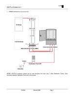
Reconfiguration of existing low-bandwidth nodes and
amplifiers with new broadband models introduces a
brief service outage during the replacement process. This
“node splitting” involves adding new nodes to deliver
services to a given set of homes passed, reducing the
number of homes serviced on each node. Node splitting
establishes new fiber connections from the headend to
the OSP by installing nodes in strategic OSP locations
within the distribution area, rerouting the coaxial feeder
cable to the new nodes, and balancing the spectrum.
To properly coordinate with the OSP network,
headend systems must also undergo changes. New
fiber distribution frames are added, along with new
laser transmitters and return path receivers. The
reconfiguration of the electrical RF splitting/combining
networks, in both forward and return directions, is
critical during this transition. Splitters and combiners
must be added, removed, or changed. With a variety
of configurations (1x8, 1x4, and 1x2) to choose from,
operators should have little difficulty finding one to
accommodate network requirements. Attenuation
pads and equalizers should be mounted on the front
of modules to allow easy access in rack-mounted
environments (see Figure 5). Broadband spectrum signal
levels change with every modification, requiring re-
balancing during the system re-engineering project.
Maintaining proper CATV RF signal levels is crucial in the
outside plant. By adjusting the output level at the node
or amplifier, operators can control RF signal levels. Signal
attenuation and equalization is applied using plug-in
attenuators and equalizers located within the node or
amplifier.
Integral attenuator pads and equalizers break the signal
flow once the pad is removed from the socket. Hitless
technology can minimize signal loss during attenuation
and equalization (see Figure 6) by incorporating a
default value built into the circuit board of the combiner.
This allows a steady signal to reach its destination
downstream.
Ensuring High Availability
Today’s high-speed data and telephony subscribers
demand always-on service without exception. While the
telecommunications industry has long targeted 99.999%
(five nines) service availability, CATV has traditionally been
more ‘relaxed’ in its commitment to always-on availability.
That attitude has changed. MSOs have become dedicated
to reducing service downtime. They are incorporating
new system maintenance and re-engineering practices
that minimize service interruptions.
As new hitless technologies enter the cable marketplace,
MSOs can now promise service continuity during
periods of maintenance, upgrades, and general system
re-engineering. Any device incorporating plug-in type
attenuators such as splitters, combiners, nodes, and
amplifiers will benefit from hitless technology. Grooming
the CATV RF spectrum via plug-in attenuators and
equalizers has revolutionized the cable industry. Signal
levels can now be accurately maintained—resulting in
uninterrupted service and satisfied subscribers.
Figure 5.
Sketch of modular combiner with front-mounted
attenuation pads
Figure 6.
Sketch of modular combiner with front-mounted
attenuation pads and hitless attenuation connection
Carrier-Class CATV Networks: Maintaining Signal Connectivity During Configuration Changes and Maintenance
Page 6
Method Average Service
Disruption
Procedure Risk
Wall-Mounted Network
with In-Line Attenuation
Pads
1-2 minutes 1. Identify appropriate cable.
2. Remove connector
3. Remove attenuation pad.
4. Install new pad value.
5. Reassemble connector.
6. Test.
7. Repeat, if necessary.
• Technicians may damage or cross-thread
connectors, requiring retermination of the
cable assembly and significantly extended
service disruption.
• Technicians may drop or misplace the
attenuation pad, resulting in extended
service disruption.
Rack-Mounted Network
with Front-Access
Attenuation Pads
10-30 seconds
1. Identify appropriate cable.
2. Remove pad.
3. Insert new pad value.
4. Test.
5. Repeat, if necessary.
• Technicians may drop or misplace the
attenuation pad, resulting in extended
service disruption.
Rack-Mounted Network
with Hitless Attenuation
Pad Connection
None 1. Identify appropriate cable.
2. Remove pad.
3. Insert new pad value.
4. Test.
5. Repeat, if necessary
• None
Web Site: www.adc.com
From North America, Call Toll Free: 1-800-366-3891 • Outside of North America: +1-952-938-8080
Fax: +1-952-917-3237 • For a listing of ADC’s global sales office locations, please refer to our web site.
ADC Telecommunications, Inc., P.O. Box 1101, Minneapolis, Minnesota USA 55440-1101
Specifications published here are current as of the date of publication of this document. Because we are continuously
improving our products, ADC reserves the right to change specifications without prior notice. At any time, you may
verify product specifications by contacting our headquarters office in Minneapolis. ADC Telecommunications, Inc.
views its patent portfolio as an important corporate asset and vigorously enforces its patents. Products orfeatures
contained herein may be covered by one or more U.S. or foreign patents. An Equal Opportunity Employer
102061AE 12/05 Revision © 2003, 2005 ADC Telecommunications, Inc. All Rights Reserved
WHITE PAPER