Tài liệu KRONE - White paper - LSA Plus Connectivity (Overview) - 2000 ppt
Bạn đang xem bản rút gọn của tài liệu. Xem và tải ngay bản đầy đủ của tài liệu tại đây (47.34 KB, 7 trang )
LSA-P
LUS
C
ONNECTIVITY
1
01/02/00 Hollands FMS1 Page 1
1. KRONE C
OMPONENTS IN THE
L
OCAL
L
OOP
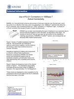
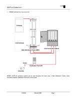
KRONE LSA-PLUS connection systems can be used throughout the Local Loop, in Main Distribution Frames, Cross-
Connection Cabinets, Distribution Points and In-house areas.
Main Distribution Frame (MDF)
Exchange
Cross-Connection Cabinet
Distribution Point (DP)
Local Exchange
Socket
Subscriber
System side
Line side
LSA-P
LUS
C
ONNECTIVITY
1
01/02/00 Hollands FMS1 Page 2
2. G
ENERAL
I
NFORMATION
LSA-PLUS Series 2
Connection, Disconnection and Switching Modules for 8 or 10 pairs:
- for fitting on Back Mount Frames of varying capacity (standard-program)
- for fitting on round profile rods as LSA-PROFIL.
- for mounting on Printed Circuit Boards by the use of soldering pins
Connectable Wiring:
Plastic insulated copper wiring with solid or stranded conductors
a) Solid Wires
Conductor diameter 0,32...0,90 mm
1,2 )
External diameter 0,70...1,60 mm
AWG 26...20
1 )
After connection with ≥0,65 mm, no longer connectable with conductors ≤0,65 mm
2 )
Other diameters on request
b) Stranded Wires
3 )
Conductor diameter 7 x 0,12...0,32 mm
External diameter 0,70...1,60 mm
AWG 26...20
3 )
Stranded wiring on Series 1 and 8 on request
LSA-PLUS cable connecting equipment
Distribution housings for internal and external use or distribution, that with additional fittings may be used to connect LSA-PLUS
Quick Connection System or already equipped with the necessary mounting components.
Number of wires per contact slot
(same type of wire and same diameter)
Series 2 max. 2
4 )
4 )
2 wires only with diameters 0,35 to 0,65 mm
LSA-P
LUS
C
ONNECTIVITY
1
01/02/00 Hollands FMS1 Page 3
3. C
ONNECTION
T
ECHNIQUES
Splice - Wire wrap - LSA-PLUS System
3.1. Conventional mechanical connections
Twisted and Soldered
Twisted and Sleeved
Wrapped around Post
(Normally soldered)
Screw Terminal Wire-wrap
Crimped
Conventional connection techniques require the wire to be cut to length and the insulation removed before the wire can be
connected. The wires are then twisted together, soldered, screwed or wrapped to finalize the connection.
Conventional mechanical connections are subject to the following stresses:
Type of stress on the
connections →
↓ Connection method
Wire breakage Dry joint High resistance
connection
Corrosion Vibration
Twisted together and
soldered
•• •
Soldered
•• ••
Splice with insulating
sleeve
•• •••
Screw terminal
••••
Wire wrap
••
Crimp
••••
•
= Stress
Reconnection of the joint, without cutting back the wire is very difficult, in the case of a crimped, soldered or wire-wrap
connection, almost impossible. The connection can be touched by hand and is also subject to environmental influences.
LSA-P
LUS
C
ONNECTIVITY
1
01/02/00 Hollands FMS1 Page 4
3.2. Wire-wrap vs. Solder vs. Screw connection
Wire-wrap:
Advantages Disadvantages
No heat is required. The heat of soldering may damage
wire insulation and certain components.
Each joint is relatively large, as it requires a number of
wire wraps.
There is less risk of high-resistance connections as a
good mechanical joint is implicit in the technique.
The technique is more suitable for joints of a permanent
or semi-permanent nature, as the wire tends to break
on repeat jointing.
The jointing operation is relatively simple. Especially sharp tags are desirable to enable the wire to
bite into sharp edges.
The joint requires tinning. The technique is not satisfactory with stranded
conductors.
There are no solder splashes. Difficulties arise when jointing small diameter wires.
Solder:
Advantages Disadvantages
The joints are smaller as not so many wire wraps are
necessary.
Heat may cause component and insulation damage.
The joint allows repeat jointing. There is a greater risk of high-resistance connections as
good mechanical joints are not so obvious.
The technique permits the use of any type of wire
(stranded, small diameter, etc.).
Jointing requires a relatively complex operation.
The joint requires tinning.
Screw:
Advantages Disadvantages
Universally available Requires correct type and size of screwdriver and wire
entry from the correct direction. Connection relies on
the experience of the technician.
The joint allows repeat jointing. There is a greater risk of high-resistance connections as
good mechanical joints are not so obvious. Possibility of
"stripping" the thread if made too tight.
The technique permits the use of any type of wire
(stranded, small diameter, etc.).
The wire termination requires stripping the insulation
and fitting the wire under the screw or into a terminal.
Screws loosen with vibration, unsuitable for use near
vibration sources e.g. road and rail traffic, heavy
machinery.
Clearly all techniques have particular merit. Any can be adopted depending upon the circumstances of the
work concerned. The main problem in all techniques is a high-resistance connection due to a poor
mechanical joint. For this reason, wrapped joints require a number of very tight wire wraps around,
preferably, a sharp-edged tag. In the soldered technique, a good mechanical joint is necessary because the
solder, which has relatively low electrical conductivity, should function merely as an adhesive and not as a
conductor. A dry joint can occur when the solder holds the wire to the tag but is not adhered to it. This is
normally due to a layer of resin flux between the wire and the tag. With screw terminations, vibration will
loosen the screws leading to arcing or high resistance connections. The weakening of joints due to exposure
to the atmosphere, physical contact, etc., is also an inherent problem in all techniques.
LSA-P
LUS
C
ONNECTIVITY
1
01/02/00 Hollands FMS1 Page 5
3.3. Insulation Displacement Connection (IDC)
Insulation Displacement Connection (IDC) connects wires without solder, screws or removing the insulation.
The technique uses a proprietary insertion tool to force the insulated wire into the jaws of a metal contact.
This action tears away the insulation from the wire and at the same time the jaws of the contact grip the conductor thus forming
an IDC with the solid or stranded conductor
Insulation
Conductor
Metal contact
A correctly terminated IDC connection prevents:
- corrosion,
- loosening due to vibration
- high resistance connections
- movement of the wire
The joint is easily remade, only the small contact area of the wire must be removed. The connection cannot be touched without
the correct insertion tool, which leads to greater contact security and means that when the joint is to be remade no particles of
solder or wire remain in the connection area.
Most important is the connection is repeatable. This means that every time a joint is made the properties of the connection will
be the same. With conventional connection techniques such as wire-wrap, solder and screw terminations the physical
connection relies on the "feel" of the technician. There is no guarantee that successive terminations will all be of the same
quality and have the same electrical properties.
IDC is a reliable, more secure and quicker contact method. This method has been proven to be the most electrically and
mechanically sound method for connecting normal telephony and data cabling.