Tài liệu ADC KRONE - Catalogue - Ethernet Connectivity Product docx
Bạn đang xem bản rút gọn của tài liệu. Xem và tải ngay bản đầy đủ của tài liệu tại đây (1.19 MB, 28 trang )
1st Edition
Ethernet/Data Connectivity
Distribution Frames
Patch Panels
AccessoriesTable of Contents
3/04 • 1287294
Ethernet/Data Connectivity
www.adc.com • +1-952-938-8080 • 1-800-366-3891
Distribution Frame
Introduction 1
Ethernet Distribution Frame 5
Glide Cable Manager 6
Patch Panels
Introduction 8
T1 Demarcation Modular Patch Panels 12
Category 6 Patch Panels 13
Category 5e Patch Panels 14
RJ45 Coupler Panel 15
Fast Ethernet Patch Panels 16
Multimedia Patch Panels 17
Accessories
High Performance Patch Cords 20
25-Pair Cable Assemblies 21
Index 221
www.adc.com • +1-952-938-8080
3/04 • 1287294
Ethernet/Data Connectivity
Ethernet Distribution Frame
Introduction
1
Centralized Cross-Connect System for
Managing Ethernet Data Services
Situation
Ethernet-based data services offer the opportunity to create differentiation, command premium
pricing, and earn higher margins for such value-added data services as transparent LANs, storage
area networks, and virtual private networks. Extending native 10/100Base-T and Gigabit Ethernet
services across the LAN, WAN, and MAN means data services are less expensive to deploy,
provision quickly, and offer exceptional reliability and security. Yet as the Ethernet distribution
system grows with more routers and switches in central offices, all of these advantages can be
quickly erased by a poorly designed cabling and connectivity architecture.
As service providers move from being vendors of T1, T3 and OC-XX data pipes to partners
providing value-added Ethernet data services, an effective business model includes the following goals:
• Create a flexible, carrier-class Ethernet delivery system, and
• Decrease operating costs of Ethernet delivery.
Reaching these goals is contingent largely upon building the correct architecture to support
Ethernet data services.
Solution
Achieving the dual requirements of lower costs and carrier-class services is possible by creating a
centralized cross-connect patching system with an Ethernet Distribution Frame (EDF). An EDF
provides a cross-connect field that ties together all Ethernet network elements from multiple floors
of the central office (CO) or point-of-presence (POP), providing a common craft interface for
performing adds, upgrades, and rearrangements on Ethernet services. In this simplified
architecture, all network elements have permanent equipment cable connections that are, once
terminated, never handled again. Technicians isolate elements, connect new elements, route
around problems, and perform maintenance and other functions using semi-permanent patch
cord connections on the front of the EDF cross-connect bay. This craft-friendly design supports
cost-effective growth and change in the Ethernet distribution system.
Figure 1
Active Network
Element Bays
Ethernet
Distribution Frame
Active Network
Element Bays
2
www.adc.com • +1-952-938-8080
3/04 • 1287294
Ethernet/Data Connectivity
Ethernet Distribution Frame
Introduction
Benefits
• Lower operating costs. As compared to direct connect or interconnect designs, the EDF cross-
connect reduces the time it takes for adding cards, moving circuits, upgrading software, and
performing maintenance. Factory assembled cable assemblies and patch panels reduce installation time
and ensure consistent quality. In addition, this high-density interface for Ethernet distribution not only
maximizes active ports but also conserves valuable floor space.
• Improved reliability and availability. Permanent connections protect equipment cables from daily
activity that can damage cables. Moves, adds, and changes are effected on the patching field instead
of on the backplanes of sensitive routing and switching equipment, enabling changes in the network
without disrupting service. With the ability to isolate network segments for troubleshooting and
reroute circuits through simple patching, Operations gains time for making proper repairs during
regular hours instead of during night or weekend shifts.
• Competitive advantage. The EDF enables rapid changes to the network. Turning-up new service is
accomplished by plugging in a patch cord instead of the labor-intensive task of making multiple hard-wired
cable connections. As a result, cards are added to the network in minutes instead of hours, decreasing
time to revenue and providing a competitive edge—faster service availability—in the marketplace.
• Investment protection. Unlike direct connection of Ethernet elements, the logical EDF cross-connect
scales easily. As elements are added, transport methods changed, and new technologies implemented,
the EDF remains constant, providing the common craft interface for managing Ethernet distribution
without service disruption.
Implementation
Creating a craft-friendly, low-cost Ethernet
distribution system fully rated for Gigabit
Ethernet consists of the following:
Ethernet Distribution Frame, providing
the central location for cross-connecting all
Ethernet network elements in a CO or POP
with semi-permanent connections. Each EDF
consists of the following ADC equipment:
• 19" or 23" UEF zone 4 rack
• Glide Cable Management system,
consisting of vertical cable managers
installed on the sides of each rack as
well as upper and lower crossover
troughs
• Category 5e patch panels, RJ45/RJ21x,
providing up to 864 available Ethernet
ports per 7' rack
• Category 5e patch cords for creating
semi-permanent cross-connections
Active Network Element Frame
houses both active equipment and one or two distribution panels. It provides permanent connections
from active Ethernet equipment to distribution panels and from distribution panels to the EDF.
• 19" or 23" UEF zone 4 rack
• Glide Cable Management system, consisting of vertical cable managers installed on the sides of
each rack as well as an upper crossover trough
• One or two Category 5e patch panels, RJ45/RJ21x, mounted at the top of each bay with active
network elements mounted below
• Category 5e patch cords for making permanent RJ45 connections between Ethernet equipment and
distribution patch panels at the top of the bay
Cross-
Connect
Patch
Cord
Permanent
Equipment
Cable
Vertical Cable
Manager
Permanent
Equipment
Patch Cord
Ethernet
Distribution Frame
Active Network
Element Frame
Active
Ethernet
Equipment
Patch
Panels
Vertical Cable
Manager
Figure 2
3
www.adc.com • +1-952-938-8080
3/04 • 1287294
Ethernet/Data Connectivity
Ethernet Distribution Frame
Introduction
Permanent Equipment Cables, providing permanent connections between the EDF and distribution
panels in each Active Network Element Frame.
• Factory terminated and tested RJ21x 24-pair Category 5e cable assemblies, up to 90 meters in length
Optical Extension Platforms, providing E/O and O/E conversion for distances greater than 100 meters
between active equipment. May also be used for interoffice transport, for transport to customer
premises, and for interface with Ethernet network elements that require fiber optic interfaces.
• Rack mount, high-density design, mounted in or adjacent to EDF and active equipment bays
Fiber Cable Management, for termination, splice, and storage of fibers where media conversion occurs.
• Rack mount FL2000 panels, wall mount FL2000 boxes, or high-density Fiber Management Trays,
all with integrated cable management that connect and protect fibers
Power Distribution, for protection of critical active equipment such as routers and switches in the
Ethernet distribution system.
• PowerWorx
®
power distribution products include options for suppression of power line noise,
uninterrupted power, and fusing for multiple amperage equipment from a single rack unit design—
all with NEBS Level 3 certification and a 15 year warranty
Design Issues
• All cable assemblies, patch cords, and patch panels should be rated Category 5, 5e, or 6 to ensure
Gigabit Ethernet performance, per EIA/TIA 568-B.1 standards for LAN cabling. While Gigabit
Ethernet is designed to run on Category 5 or higher cabling, Category 5e and Category 6 cables
and components are preferred for new build-outs.
• Cabling distance between active network elements should be no more than 100 meters, which
includes both permanent cables and semi-permanent patch cords. Patch cord length should be less
than 10 meters due to attenuation from stranded cable. Distances greater than 100 meters require
optical transport and media conversion at both the EDF and active bays.
• Due to TIA standards that limit the proximity of connection points, limit the number of passive
connection points between active equipment to four with length between EDF and active
equipment of at least 15 meters to minimize electrical interaction between patch panels.
• Proper routing, management, and protection of cables and patch cords in both the EDF and active
element bays is essential for carrier-class reliability and availability. A system of vertical cable
managers with integrated slack managers not only offers proper management of cables, but also
provides increased bay density as compared to systems using horizontal cable managers. Vertical
cable managers should be sized 8 inches wide, except for inter-rack applications that require 10- or
12-inch widths.
• Select a standard patch cord length of less than 10 meters for the EDF and use slack managers in
vertical cable managers for routing and storage of extra cable lengths (see Figures 3 and 4). This
ensures that the cross-connect is easy to administer while providing protection for patch cords.
• Choose preconnectorized patch panels with RJ45 interfaces on the front and RJ21x interfaces on
the rear. Punchdown connectors (110) are reliable, but take more time to install and are prone to
installation errors such as cross wiring that disable ports. Gold-on-gold contacts between modular
interfaces on patch panels are pre-assembled cable assemblies ensure reliable and consistent
performance.
4
www.adc.com • +1-952-938-8080
3/04 • 1287294
Ethernet/Data Connectivity
Ethernet Distribution Frame
Introduction
Figure 3. Connect ports to the same side of the same EDF
cross-connect bay using vertical cable managers with slack
managers for handling extra cable lengths.
Figure 4. Upper and lower crossover managers with
vertical cable managers enable connection of ports on
opposite sides of the EDF cross-connect bay.
• Where E/O conversion is required, media converters should feature clear separation of optical,
electrical, and power supply cables to ensure system reliability. Distributed power architecture is also
preferred for improved performance, reliability, and system availability. Built-in intelligence enables
time saving in installation and troubleshooting with full view of UTP and optical link integrity from
one end of the circuit.
• System reliability depends upon proper management of fiber cables. Fiber panels and boxes should
include removable angled retainers as well as integrated splicing and slack storage. In addition,
single circuit access to fibers provides improved system reliability and availability by reducing the
chance for damage to adjacent fibers during routine maintenance of individual fibers.
Conclusion
Earning customers for value-added data services requires innovative offerings, a competitive price, and
superior reliability and availability. Extending native Ethernet across the LAN, WAN, and MAN opens the
door for new data services. However, building an infrastructure that keeps operating costs low while
providing exceptional reliability and 99.999% availability requires a centralized cross-connect EDF
designed to manage growth and change without disrupting service.
1
1
2
2
1
1
2
2
5
www.adc.com • +1-952-938-8080
3/04 • 1287294
Ethernet/Data Connectivity
Ethernet Distribution Frame
Ethernet Distribution Frame
7' EIA 19" UEF Zone 4 Rack
Glide Cable Management Adapter
PowerWorx
®
Power Distribution Panel
2RU Horizontal Cable Manager
Media Converter
Fiber Management Tray
48-Port Category 5e Panel
8" Glide Cable Management
Bottom Crossover Trough
ADC’s Ethernet Distribution Frame (EDF) forms a central patching location between active Ethernet network
elements. By creating a centralized craft interface for adds, upgrades, and rearrangements on Ethernet
equipment, the EDF enables change without service disruptions. This central patching location provides a
logical and easy-to-manage infrastructure due to two design characteristics:
• All network elements have permanent equipment cable connections that are, once terminated,
never handled again.
• All changes, circuit rerouting, upgrades, maintenance and other activities are accomplished using
semi-permanent patch cords on the front of the EDF cross-connect bay.
6
www.adc.com • +1-952-938-8080
3/04 • 1287294
Ethernet/Data Connectivity
Ethernet Distribution Frame
Glide Cable Manager
Features
• Integrated front, rear, horizontal, and vertical cable management
• Patented rib cage design eliminates horizontal support trays and bars
• Supports up to 912 ports on a single rack
• Built-in bend radius protection ensures network integrity
• Designed for quick and easy moves, adds, and changes
• Optional slack managers available for 8-, 10-, and 12-inch widths
• Fits standard EIA rack with three-inch channel
• Used for single rack or as inter-rack unit
• Optional crossover troughs and horizontal cable managers available
• Optional EIA-standard horizontal support bars available
Description
Glide cable manager, vertical mount –
to equip both sides of a 7-foot rack, order
two Glide Cable Manager units
6", front only, without slack manager
6", front only, with slack manager
6", without slack manager
8", without slack manager
10", without slack manager
12", without slack manager
8", with slack manager
10", with slack manager
12", with slack manager
Crossover trough, 2 RU
Crossover trough, 4 RU
Black metal covers
41" x 6", four per pack
41" x 8", four per pack
41" x 10", four per pack
41" x 12", four per pack
Black metal cover, hinged
41" x 6", two per pack
Ordering Information
Ordering Number
ADCCMVIB06F-2
ADCCMVIBS06F-2
ADCCM-06
ADCCM-08
ADCCM-10
ADCCM-12
ADCCMS-08
ADCCMS-10
ADCCMS-12
ADCCMTG02
ADCCMTG04
ADCCMVIBC06B4
ADCCMVIBC08B4
ADCCMVIBC10B4
ADCCMVIBC12B4
ADCC06-2
Glide Cable Manager with
Slack Managers
Cover in Black Metal
Glide Cable Manager
Shown in Cabinet
2 RU Crossover Trough
4 RU Crossover Trough
Horizontal Cable Manager
Installation Drawing for Glide
Cable Manager, Cabinet Mount
Glide Cable Manager,
Cabinet Mount
Slack Manager
Stabilizer
7
www.adc.com • +1-952-938-8080
3/04 • 1287294
Ethernet/Data Connectivity
Ethernet Distribution Frame
Glide Cable Manager
Description
Glide cable manager, cabinet mount –
ships 4 per pack
6" x 10 RU
6" x 20 RU
Glide cable manager, cabinet mount,
with cable retention – ships 4 per pack
3" x 20 RU
6" x 20 RU
Ordering Information
Ordering Number
ADCCMVIB-CB10-4
ADCCMVIB-CB-4
ADCCMVIB-3CB20-4
ADCCMVIB-6CB20-4
Notes: Equips standard 7' cabinet with front or rear cable management.
Order two 4-packs to equip front and rear of cabinet.
Description
Crossover troughs
2 RU, black
4 RU, black, 23" rack
4 RU, black
Horizontal cable managers
2 RU
3 RU
4 RU
With slack managers, 3 RU
With slack managers, 4 RU
Rear cable management bar, 19"
1" extension
Rear cable management bar, 19"
4" extension
Slack manager
Stabilizers
6.18"
8.38"
10.18"
12.18"
Extender brackets, 19" to 23"
1 RU
2 RU
4 RU
Ordering Information
Ordering Number
ADCCMTG02
ADCCMTG04-23
ADCCMTG04
ADCCMHIB-2U
ADCCMHIB-3U
ADCCMHIB-4U
ADCCMHIBS-3U
ADCCMHIBS-4U
ADCCMRSB
ADCCMRSB-4
ADCCMVIBSP
ADCCMVESB06
ADCCMVESB08
ADCCMVESB10
ADCCMVESB12
EB-17B
EB-35B
EB-70B
Note: Stabilizer used at end of line-up for each Vertical Integrator section.
Description
7' equipment racks
Self-assembly aluminum relay rack, 3" channel
Black
Brushed aluminum
Welded steel relay rack, 3" channel, black
Welded steel relay rack, Zone 4 rated, black
Unequal flange
Network unequal flange
Ordering Information
Ordering Number
ADCRACKBLK73
ADCRACKMF73
ADCRACKBLK73WS
ADCRACKBLK73UE
PWUEF-7ERN-BLK
Spacing
19" EIA
19" EIA
19" EIA
19" EIA
23" EIA
8
www.adc.com • +1-952-938-8080
3/04 • 1287294
Ethernet/Data Connectivity
Patch Panels
Introduction
Ethernet Connectivity
Selection Tutorial
Category 5, 5e or 6? 110 punchdown, or RJ to RJ? T568A or T568B? Shielded or unshielded?
Will I choose the right Ethernet patch panel for my application? Will this choice work with future
applications? Am I getting the best overall value?
With all the choices you face as you design your network and select equipment, including available
Ethernet patch panels, it’s easy to become confused and frustrated. Ultimately your choice of
Ethernet panels should fit the applications you plan to run. ADC wrote this short tutorial to guide
you through these decisions, to make them as painless as possible and offer you the best solution
for your network.
First, let’s ask a few key questions. Your answers will help guide you in the decision process. Next,
we will briefly discuss each of the most popular options available so you can draw conclusions based
on your network needs.
Discovery Questions
• What applications are you or do you plan to run on this network? 10/100Base-T? 1000Base-T?
• What type of network are you designing? Data center? Data backbone? LAN?
• Is the project a new network installation or addition to existing network?
• Is the installation being built to expand existing capacity with current data capabilities or is it
for new, faster data applications?
Answers to these questions will guide you to a particular cable type, a particular data patch panel,
and the means to terminate the cable into the patch panel — whether the terminations into the
patch panel involve “punchdown” cable terminations, pre-made telco-type multi-pair cable ends,
or standard RJ45 cable ends.
The general guidelines for network transmission capabilities segment the data network; data
center and data network backbone system applications require the highest level of transmission
capabilities, while feeds to work areas generally require a bit less. However, all network
connectivity should be designed with only the highest network engineering standards available.
Category 5, 5e, and 6 Cabling
The Telecommunications Industry Association (TIA) standards forming group consists of a variety
of industry experts including connectivity and cable manufacturers, distributors, installers, and end
customers. The TIA determines certain transmission characteristics that must be met to qualify a
cable for certain network applications.
Category 5 cabling is currently the most prevalent wiring in existing buildings. Electrical
characteristics defined by the TIA specify near end cross-talk (NEXT), attenuation, and return loss
to 100 MHz. The TIA Technical Services Bulletin (TSB) 95 recommends additional criteria for far end
cross-talk (FEXT).
9
www.adc.com • +1-952-938-8080
3/04 • 1287294
Ethernet/Data Connectivity
Patch Panels
Introduction
Category 5e is currently the minimum TIA recommended category of wiring for new installations.
Electrical characteristics for NEXT, FEXT, attenuation, and return loss are specified to 100 MHz. NEXT
performance is slightly better than category 5.
Category 6 is gaining popularity for new installations. Electrical characteristics for NEXT, FEXT,
attenuation, and return loss are specified to 250 MHz. Improvements in all electrical parameters are
part of the higher TIA Category 6 standard.
Category 7 cabling is a developing standard. The International Standards Organization (ISO) is leading
the standardization efforts for this new individually-shielded, overall-shielded, 4-pair cable with
transmission specifications referenced to 600 MHz. The cable end interface will probably be something
other than the familiar RJ45 connector, mainly to differentiate the Category 7 installation from existing
lower-bandwidth infrastructure.
So, which should you use? There is quite a bit of misleading information in the industry on this subject,
the biggest myth being that Category 6 is required to run Gigabit Ethernet over copper (1000Base-T).
Actually 1000Base-T was designed by the IEEE to run on Category 5. As long as the Category 5 is
installed according to TIA-568-B standards and meets the testing criteria in TIA TSB 95, 1000Base-T
will perform satisfactorily on Category 5. However, as of this writing, the TIA recommends Category
5e over Category 5 as the minimum cabling for new network infrastructure installations.
When do I use Category 6? Does the application standard (i.e., Gigabit Ethernet, 10G, etc.) specify
Category 6 as a minimal requirement? The TIA is making recommendations to the IEEE 802.3ae and
the 10 Gigabit Ethernet Alliance, who are currently working on 10 Gigabit cabling systems, that any
10 Gigabit Ethernet designed to run on copper cabling use Category 6 because of its improvement in
signal to noise. The good news is that Category 6 is backward compatible and will have no trouble
running existing applications such as 10/100Base-T and 1000Base-T.
Cable Type Summary
The chart below summarizes the industry standard UTP cable types used in current networking
installations.
In addition to the UTP cabling described above, you should understand the issues of cable shielding,
and stranded versus solid cable.
Shielded vs. Unshielded Twisted Pair
Unshielded twisted pair (UTP) cabling provides immunity to electromagnetic interference (EMI) with the
properties of the two conductors that make up a transmission pair being twisted together. When UTP
cabling encounters electrical interference, the noise crossing the twisted pairs is cancelled by the twists
in the cable (called “Common Mode Rejection”, a subject outside the scope of this introduction).
Standard Category 5, 5e and 6 cables contain four unshielded twisted pairs of conductors. For
10BASE-T and 100BASE-TX applications, only two pairs are used, one for the transmit circuit and one
for receive circuit. For 1000BASE-T (Gigabit Ethernet) all four pairs are required.
The term “shielded twisted pair” cabling can be misleading. There are actually two methods of
shielding a twisted pair cable. Screened twisted pair cable (ScTP) provides an overall screen or metal
foil around the four pairs of conductors, but each individual twisted pair is unshielded. Shielded
Category Test Frequency 10/100BaseT 1000BaseT Future Applications Relative Cost
Cat 5 100 MHz Yes Yes No $
Cat 5e 100 MHz Yes Yes Maybe $
Cat 6 250 MHz Yes Yes Yes $$
Cat 7 600 MHz Yes Yes Yes $$$$
10
www.adc.com • +1-952-938-8080
3/04 • 1287294
Ethernet/Data Connectivity
Patch Panels
Introduction
Twisted Pair cable (STP) has each individual pair shielded, plus an overall screen around the four
individually shielded pairs. This makes a very expensive and hard to install cable - the legacy token ring
IBM Type 1 cable and Category 7 are examples of STP cable. STP cable requires metal end connectors
and metal jacks that bond the cable shield to earth ground to carry the interfering signals safely away
from the signal conducting pairs – failure to connect the cable shield to earth ground results in the
shield coupling the interfering noise to the conductors, providing very poor transmission performance.
Most of the world uses UTP cabling, with some exceptions located in a few countries in Europe.
Stranded vs. Solid Conductor Cable
Stranded cable is flexible and often used for patch panel jumpers and work area connections. Stranded
cabling is used for shorter patching applications for its flexible cable construction, but also exhibits
higher attenuation due to the smaller diameter conductors, and as such should not be used for long,
permanent installations. Solid conductor cable is used for the “horizontal” cable runs from the
telecommunications room to the work area wall outlet. The typical gauge for Category 5e cable is 24
AWG. Category 6 is 23 AWG - the larger conductor diameter improves attenuation characteristics and
signal-to-noise ratio versus the smaller conductor diameter of Category 5e.
Wiring Schemes, T568A vs. T568B
Wiring schemes also raise a variety of questions:
Q: What’s the difference between T568A and T568B?
A. The only difference is the positioning of the Green and Orange pairs of wires (see figure 1)
Figure 1
Typical RJ45 cable ends, T568A vs. T568B
Q: Is there a performance difference between T568A and T568B?
A: No. Both wiring schemes have to meet the same performance criteria.
Q: Why two schemes?
A: The reason is outside of the scope of this paper but it is related to old telephone legacy issues.
All you really need to know is that there are two schemes, and how to deal with them.
T568A T568B
Pair 3
Pair 1
Pair 4
Pair 2
Pair 2
Pair 1
Pair 4
Pair 3
11
www.adc.com • +1-952-938-8080
3/04 • 1287294
Ethernet/Data Connectivity
Patch Panels
Introduction
The solution really is fairly simple: Just pick one wiring scheme and use it consistently throughout your
network. The only problem you would ever encounter would be if the two wiring schemes were
accidentally mixed in an installation. T568B is the predominate scheme in the United States; T568A is
popular in Canada and in many other countries. The safest way to determine which to use is to check
with the network equipment provider to determine the predominant wiring scheme used in the
equipment. The reason for this check is quite simple: you can change the wiring scheme used in the
network but you cannot change the wiring scheme used in the network equipment.
Patch Panel Rear Termination Options
Popular choices for patch panel rear terminations include 110 Insulation Displacement Contact (IDC)
punchdown termination, and connectorized cable end terminations (RJ45 and RJ21X).
Many popular data patch panels are designed using 110 IDCs, requiring the manual punchdown
termination of each individual wire. A typical 24-port panel requires 192 individual punchdown
terminations. With this many manual terminations, installation mistakes are common, including
incorrect wire mapping (cross-wiring), opens, shorts, and excessive untwisting of the wire pairs.
Terminating the “horizontal” cabling from the work areas in the telecommunications room typically
uses 110 IDC punchdown panels.
For patch-panel-to-patch-panel connections in a data center or telecommunications room,
preterminated cable assemblies and connectorized patch panels can improve installation time and
connectivity success. A preconnectorized solution dramatically decreases the assembly time and
increases the quality of the termination, as the contact points are typically gold-on-gold with high
contact forces. Preconnectorized solutions do require up-front planning — the distances between
panels must be determined so the correct cable assembly length can be ordered.
RJ45-to-RJ45 and RJ45-to-RJ21X panels are the two most popular preconnectorized systems. The
RJ21X, also known as 50-pin telco or 25-pair Amphenol
®
connectors, is popular because six 4-pair
Ethernet (1000BaseT) or twelve 2-pair Ethernet (10/100BaseT) circuits can be terminated at one time
on a panel using the correct multi-pair cable assembly.
ADC Solutions
Listed below are some of ADC’s panel solutions that meet the recommendations above. Please contact
ADC’s Technical Assistance Center for more information on these or any other solutions.
Catalog Number Category Wiring Scheme Rear Termination Applications Supported Page
ADCPP24505 5e Universal T568A/B RJ45 All 15
ADCPP245800BTEL 5e T568B RJ21X All 16
ADCPP245100TEL 5 10/100Base-T Specific RJ21X 10/100Base-T 16
ADCPP245EB110 5e T568B 110 All 14
ADCPP245EA110 5e T568A 110 All 14
ADCPP24C6 6 Universal T568A/B 110 All 13
12
www.adc.com • +1-952-938-8080
3/04 • 1287294
Ethernet/Data Connectivity
Patch Panels
T1 Demarcation Modular Patch Panels
Features
• Bantam nonintrusive T1 signal monitoring
(MPP-N28BA1 only)
• RJ48X (T1 loopback) or RJ45C (no loopback)
wiring
• Variety of rear termination options (wire-wrap,
64-pin, 50-pin)
• Category 3 performance
• Variety of mounting options (19- or 23-inch
rack mounting, wall mounting)
• Compatible with industry standard RJ45
patch cords
ADC modular T1 demarcation patch panels feature RJ48X or RJ48C wiring with a variety of rear
termination options. The T1 demarcation patch panels offer the end users a familiar RJ interface by which
the T1 signal can be accessed via industry standard RJ45 patch cables.
Port Count Wiring Rear Termination EIA Mounting Ordering Number
28 (with bantam RJ48X 64-pin or wire-wrap 2 RU x 19" or 23" MPP-N28BA1
monitoring ports)
28 RJ48X Wire-wrap 1 RU x 19" or 23" MPP-GDXBA1
28 RJ48X 64-pin 1 RU x 19" MPP-DXZBA0
14 RJ48X Wire-wrap, front access Wall mount, 3.5" x 19" MPP-CXZXF4
8 RJ48X Wire-wrap, front access Wall mount, 3.5" x 14" MPP-CXZXF3
5 RJ48X Wire-wrap, front access Wall mount, 3.5" x 9.9" MPP-CXZXF2
28 RJ48C Wire-wrap 1 RU x 19" or 23" MPP-GDXBA2
24 RJ48C shielded 50-pin shielded 1 RU x 19" MPP-CXFBA1-S
24 RJ48C 50-pin 1 RU x 19" MPP-CXFBA1
32 RJ48C 50-pin 1 RU x 19" MPP-CXZXBT2A
Ordering Information
MPP-N28BA1 (front)
MPP-N28BA1 (rear)
MPP-CXFBA1 (front)
RJ48X has a shorting bar between transmit and receive
pins 1, 2 and 4, 5 to allow for T1 signal loopback when
no patch cord is present. The RJ48C has no shorting bar.
12345 678
RJ48x
Pair 1 Pair2
12345 678
RJ48C
Shorting Bar
Pair 1 Pair2
13
www.adc.com • +1-952-938-8080
3/04 • 1287294
Ethernet/Data Connectivity
Patch Panels
Category 6 Patch Panels
96-Port Patch Panel
Rear View,
24-Port Patch Panel
48-Port Patch Panel
Features
• Category 6 performance
• Universal T568A and T568B wiring
• Backward compatible in component, link,
and channel
• Patented angle-right/angle-left port rotation
feature reduces cable strain, reduces cable
congestion, and enforces improved cable
management with orderly flow of patch cords
• Color-coded, gas-tight 110 IDC provides
sound connections for terminating stations,
equipment, or tie cables
• Supports 10Base-T and 100Base-T Ethernet,
1000Base-T Ethernet, token ring, up to 155
Mbps ATM, and proposed 1000Base-TX
• Supports any next generation applications
designed for TIA/EIA Category 6 transmission
requirements
DIMENSIONS (W X H)
1 RU 19.0" x 1.75" (48.26 x 4.45 cm)
2 RU 19.0" x 3.50" (48.26 x 8.89 cm)
4 RU 19.0" x 7.0" (48.26 x 17.78 cm)
Description Port Count Wiring Configuration Rack Units Ordering Number
Category 6 24 Universal T568A/B 1 ADCPP24C6
patch panels 48 Universal T568A/B 2 ADCPP48C6
96 Universal T568A/B 4 ADCPP96C6
Ordering Information
14
www.adc.com • +1-952-938-8080
3/04 • 1287294
Ethernet/Data Connectivity
Patch Panels
Category 5e Patch Panels
Features
• Exceeds Category 5e requirements
• Durable construction for maximum performance
- Steel frame with black corrosion-resistant
finish
- High-impact UL 94 V-O polycarbonate used
for all plastic parts
- Modular 8-pin, 4-pair jacks
• Advanced features include:
- Patented angle-right/angle-left ports
- Color-coded icons for quick port identification
• Includes labeling for front and rear
• Supports 10Base-T, 100Base-T, and 1000Base-T
Ethernet, token ring, 155 Mbps ATM
• Supports network speeds up to 1000 Mbps
Category 5e Patch Panels
DIMENSIONS (W X H)
1 RU 19.0" x 1.75" (48.26 x 4.45 cm)
2 RU 19.0" x 3.50" (48.26 x 8.89 cm)
4 RU 19.0" x 7.0" (48.26 x 17.78 cm)
Description Port Count Wiring Configuration Rack Units Ordering Number
Category 5e 24 T568B 1 ADCPP245EB110
patch panels 24 T568A 1 ADCPP245EA110
48 T568B 2 ADCPP485EB110
48 T568A 2 ADCPP485EA110
96 T568B 4 ADCPP965EB110
96 T568A 4 ADCPP965EA110
Ordering Information
48-Port
24-Port
15
www.adc.com • +1-952-938-8080
3/04 • 1287294
Ethernet/Data Connectivity
Patch Panels
RJ45 Coupler Panel
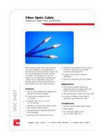
ADC's RJ45 coupler panel provides feed-through data and voice connectivity on the front and rear for
Category 5e and 6 applications. Connectivity on the front of the panel accommodates standard RJ45 patch
cords. Connectivity for hubs, routers and other active equipment on the back of the panel is also designed
for RJ45 patch cords – creating a convenient connection field for data applications. Includes port labeling
for front and rear. Width is 48.26 cm (19-inch).
Description Port Count Category Rack Units Ordering Number
RJ45 24 6 1 ADCPP24606
coupler panel 48 6 2 ADCPP48606
24 Shielded 6 1 ADCPP24RJ6-S
24 Shielded 5e 1 ADCPP24RJ5E-S
24 5e 1 ADCPP24505
48 5e 2 ADCPP48505
16 5e 1 ADCPP16KSRJRJ
32 5e 1 ADCPP32KSRJRJ
Ordering Information
RJ45 Coupler Panel
(Rear View)
RJ45 Coupler Panel
(Front View)
16
www.adc.com • +1-952-938-8080
3/04 • 1287294
Ethernet/Data Connectivity
Patch Panels
Fast Ethernet Patch Panels
Features
• Durable, quality construction for maximum
performance
• Saves time in moves, adds, and changes
• Features secure and convenient 25-pair connections
on the rear
• Modular 8-pin, 4-pair jacks on the front
• 5100 pin-out is 1,2-3,6
• 5800 has all pairs wired
• Includes write-on labels on front
• 5100 supports 10Base-T and 100Base-T Ethernet
• 5800 supports 10/100 and 1000Base-T Ethernet
• Optional icons speed circuit identification
5100 Patch Panel, 48-Port
The first step to integrate Fast Ethernet traffic into a twisted pair network is to terminate both station side
and equipment side connections on high performance ADC patch panels.
For the Ethernet switching system, 5100 and 5800 patch panels provide convenient 25-pair (50-pin)
female RJ21x connections on the rear, with rugged 8-pin modular jacks on the front. Port identification is
accomplished with write-on port labels and optional icons.
DIMENSIONS (W X H)
1 RU 19.0" x 1.75" (48.26 x 4.45 cm)
2 RU 19.0" x 3.50" (48.26 x 8.89 cm)
Description Pin-Out Port Count Rear Connector Rack Units Ordering Number
5100 patch panel 1,2-3,6 24 RJ21x 2 ADCPP245100TEL
5100 patch panel 1,2-3,6 48 RJ21x 2 ADCPP485100TEL
5800 patch panel, T568B 1-8 24 RJ21x 1 ADCPP245800BTEL
5800 patch panel, T568B 1-8 48 RJ21x 2 ADCPP485800BTEL
Ordering Information
17
www.adc.com • +1-952-938-8080
3/04 • 1287294
Ethernet/Data Connectivity
Patch Panels
Multimedia Patch Panels
48-Port Panel with Angled 6000 Modular Jacks and
Flat 6000 BNC Media Adapters
Multimedia Patch Panels Feature Single Circuit Access
Features
• Category 6 performance
• Front or rear loading, single-circuit access
saves time in moves, adds, and changes
• The highest density panel available
• Build each patch panel for twisted pair, fiber,
and coax applications using any mix of 6000
modular jacks and 6000 media adapters
- Jacks and media adapters installed and
removed in single circuits
- For Category 6 and Category 5e modular
jack applications
- Singlemode and multimode fiber
applications using LX.5
®
, LC, SC, duplex
SC, and ST
®
media adapters
- Handles applications for BNC, F-adapter,
RCA-adapters, and S-Video adapters
• Creates angle-right/angle-left or conventional
flat panel profile
• Simple installation and removal of individual
jacks/adapters allows for rapid change-over
and minimized downtime
• Supports 10Base-T, 100Base-T, and
1000Base-T Ethernet, token ring, up to
155 Mbps ATM, and proposed 1000Base-TX
• Includes port numbers or row identification
and write-on panel labels
• Jacks and adapters install without panel
faceplates or pairing of jacks/adapters
• Available in standard and high-density
port sizes
- Standard sizes – 24-ports/1 RU, 48-ports/
2 RU, 96-ports/4 RU
- High-density sizes – 32-ports/1 RU and
72-ports/2 RU
24-Port Panel with Flat 6000 Modular Jacks
Description Port Rack Ordering
Count Units Number
6000 24 1 ADCPP246SUM
multimedia 32 1 ADCPP326SUM
patch panel 48 2 ADCPP486SUM
chassis 72 2 ADCPP726SUM2U
96 4 ADCPP966SUM
Ordering Information
6000 24 1 ADCPP246SUMR3
multimedia
3" recessed
patch panel
chassis
Note: Order modular jacks and media adapters
separately.
DIMENSIONS (W X H X D)
1 RU 19.0" x 1.75" x 0.50" (48.26 x 4.45 x 1.27 cm)
2 RU 19.0" x 3.47" x 0.50" (48.26 x 8.81 x 1.27 cm)
4 RU 19.0" x 6.97" x 0.50" (48.26 x 17.70 x 1.27 cm)
18
www.adc.com • +1-952-938-8080
3/04 • 1287294
Ethernet/Data Connectivity
Patch Panels
Multimedia Patch Panels – 6000 Modular Jacks and Icons
Features
• Exceeds Category 5e and Category 6 performance requirements
• Backward compatible in component, link, and channel
• Supports 10Base-T and 100Base-T Ethernet, 1000Base-T Ethernet, token ring, up to 155 Mbps ATM, and
1000Base-TX
• Supports any next generation applications designed for TIA/EIA Category 6 transmission requirements
• Available in flat profile or angled version for bend radius protection in universal T568A and T568B
wiring schemes
• Includes one jack with color-coded 110 IDC connections and clear stuffer cap
• Universal T568A/B wiring
Description Jack Type Wiring Configuration Category Ordering Number
6000 Angled Universal T568A/B 6 ADCJA6XX*
modular jacks Angled Universal T568A/B 5e ADCJA5XX*
Flat Universal T568A/B 6 ADCJF6XX*
Flat Universal T568A/B 5e ADCJF5XX*
Blank inserts ADC6SADUMBKXX*
(Ships 10
per pack)
Ordering Information
*Replace the XX in the ordering number with choice of color, below.
*Replace the XX in the ordering number with choice of color, below.
00 = Electrical Ivory
01 = Office White
02 = Black
03 = Red 08 = Orange 11 = Brown
04 = Green 09 = Yellow
05 = Blue 10 = Purple
Icon
Description Ordering Number
Icons for angled
modular jacks
(Ships 25 per pack)
Blank ADC6SICNPXX*
Data ADC6SICNDXX*
Voice ADC6SICNVXX*
Ordering Information
Description Ordering Number
Icons for flat modular
jacks and patch panels
Blank ADCICBXX*
Data ADCICDXX*
Voice ADCICVXX*
Ordering Information
6000 Modular Jacks
Icons
Angled
Flat
19
www.adc.com • +1-952-938-8080
3/04 • 1287294
Ethernet/Data Connectivity
Patch Panels
Multimedia Patch Panels – 6000 Media Adapters
Features
• Fully supports fiber, coax, RCA, and
S-Video applications
• Available in angled or flat profiles
• Blank inserts available to fill unused ports
on 6000 multimedia patch panels
6000 Media Adapters
Description
Flat media adapters
Singlemode LX.5
®
Multimode LX.5
®
Singlemode LC
Multimode LC
Singlemode SC
Singlemode duplex SC
Multimode SC
Multimode duplex SC
Singlemode ST
®
Multimode ST
®
BNC
F-adapter
RCA-adapter
S-Video
Angled media adapters
Singlemode LX.5
®
Multimode LX.5
®
Singlemode LC
Multimode LC
Singlemode SC
Singlemode duplex SC
Multimode SC
Multimode duplex SC
Singlemode ST
®
Multimode ST
®
Blank inserts (Ships 10 per pack)
Ordering Information
Ordering Number
ADC6SADUMSMLX5XX*
ADC6SADUMMMLX5XX*
ADC6SADUMSMLCXX*
ADC6SADUMMMLCXX*
ADC6SADUMSMSCXX*
ADC6SADUMSMDSCXX*
ADC6SADUMMMSCXX*
ADC6SADUMMMDSCXX*
ADC6SADUMSMSTXX*
ADC6SADUMMMSTXX*
ADC6SADUMBNCXX*
ADC6SADUMFCNXX*
ADC6SADUMRCAFXX*
ADC6SADUMSVHSFXX*
ADC6SADANSMLX5XX*
ADC6SADANMMLX5XX*
ADC6SADANSMLCXX*
ADC6SADANMMLCXX*
ADC6SADANSMSCXX*
ADC6SADANSMDSCXX*
ADC6SADANMMSCXX*
ADC6SADANMMDSCXX*
ADC6SADANSMSTXX*
ADC6SADANMMSTXX*
ADC6SADUMBKXX*
*Replace the XX in the ordering number with choice of color, below.
00 = Electrical Ivory
01 = Office White
02 = Black
20
www.adc.com • +1-952-938-8080
3/04 • 1287294
Ethernet/Data Connectivity
Accessories
High Performance Patch Cords
Features
• Exceeds Category 5e requirements as well as
ISO/IEC 11801 Telecommunications Standards
• Insert and remove patch cord without pulling back
strain relief boot
• Every patch cord is tested to guarantee quality
• High-performance plugs preserve signal integrity
and minimize crosstalk
• Fully supports data rates up to 1000 Mbps
• Wide variety of lengths and colors promotes
simple, inexpensive installation and easy
identification
• Strain-relief boot limits bend radius and
increases durability
1 2 3 4 5 6
7 8 9 10 11 12
13 14 15 16 17 18
19 20 21 22 23 24
25 26 27 28 29 30
31 32 33 34 35 36
3
7 3
8 39
40
41 42
43 44 45 46 47 48
Category
5
2
3
4
5
6
1
8
9
1
0
1
1
1
2
7
13
1
4
1
5
1
6
1
7
1
8
19
2
0
2
1
2
2
2
3
2
4
2
3
4
5
6
1
8
9
1
0
1
1
1
2
7
13
1
4
1
5
1
6
1
7
1
8
19
2
0
2
1
2
2
2
3
2
4
Work
Station
Horizontal Cable
Fast Ethernet Hub
5100 Cable
5100 Patch Panel
Patch Cord
5000E Patch Panel
*Replace the XX in the ordering number with desired length in feet: 03, 05, 07, 10, 15, 20, 25 or 50 feet.
Custom colors and lengths available; please contact ADC.
Description Category Color Ordering Number
Patch cord, with boots 6 White ADCPC-66CHB-WTXX*
6 Gray ADCPC-66CHB-GYXX*
6 Blue ADCPC-66CHB-BLXX*
Patch cord, with boots 5e White ADCPC-RRC6B-WTXX*
5e Gray ADCPC-RRC6B-GYXX*
5e Blue ADCPC-RRC6B-BLXX*
Ordering Information
21
www.adc.com • +1-952-938-8080
3/04 • 1287294
Ethernet/Data Connectivity
Accessories
25-Pair Cable Assemblies
Features
• Convenient 25-pair/50-pin RJ21x connections
• Connectors available in:
- 180° exit angle
- Hydra terminated with twelve numbered RJ45 plugs
• Exceeds Category 5 PowerSum requirements
• Supports 10Base-T and 100Base-T Ethernet
The 25-pair cable assemblies are Category 5 PowerSum telco cables that provide precise connectivity
between Fast Ethernet switches and 5100 or 5800 Patch Panels.
With the convenience and precision of RJ21x connectors, 25-pair cable assemblies easily handle even high
density Fast Ethernet switch configurations. In addition, the durable connectors feature a lock-down system
that eliminates intermittency often associated with other telco cables.
*Replace the XX in the ordering number with desired length in feet: 05, 10, 15, 20, 25, 30, 35, 40, 45, or 50 feet.
Description Connector 1 Connector 2 Ordering Number
25-pair cable assemblies Straight Exit 180º Straight Exit 180º ADCPC-T3T3-5100-XX*
Ordering Information
RJ21x/RJ21x
Note: Hydra connectors consist of 12 RJ45 plugs pinned 1,2-3,6.
*Replace the XX in the ordering number with desired length in feet: 06, 10, or 15 feet.
Description Connector 1 Connector 2 Ordering Number
25-pair cable assemblies Straight Exit 180º Hydra, longest to shortest plug: 1-12 ADCPC-T3H1-5100-XX*
Straight Exit 180º Hydra, longest to shortest plug: 12-1 ADCPC-T3H2-5100-XX*
Straight Exit 180º Hydra, plugs same length ADCPC-T3H3-5100-XX*
Ordering Information
RJ21x/Hydra