Tính toán bù trừ hiện tượng co giản kích thước khi tạo hình tấm bằng phương pháp SPIF
Bạn đang xem bản rút gọn của tài liệu. Xem và tải ngay bản đầy đủ của tài liệu tại đây (1.31 MB, 11 trang )
Science & Technology Development, Vol 13, No.K4- 2010
A CALCULATION
FORMING
FOR COMPENSATING
METAL
THE ERRORS
SHEET BY SINGLE
DUE TO SPRINGBACK
POINT INCREMENTAL
FORMING
WHEN
(SPIF)
Nguyen Thanh Nam", Vo Van Cuong”, Le Khanh Dien, Le Van Sy
(1) National Key Lab of Digital Control and System Engineering, VNU-HCM
(2) University of Technology, VNU-HCM
(3) University of Padova, Italy
(Manuscript Received on July 09", 2009, Manuscript Revised December 29", 2009)
ABSTRACT: The question of compensating for the error of dimension due to springback
phenomenon when forming metal sheet by SPIF method is being one of the challenges that the
researchers of SPIF in the world trying to solve. This paper is only a recommendation that is based on
the macro analysis ofa sheet metal forming model when machining by SPIF method for calculating a
reasonable recompensated feeding that almost all researchers have not been interested in yet:
- Considering
authors
attempt
the metal sheet workpiece
to calculate for compensating
is elasto-plastic and the sphere tool tip is elastic,
the error of dimension
due
to elastic deforming
the
of the
tool tip.
- The metal sheet is clamped by a cantilever joint that has an evident sinking at the machining
area that is also calculated to add to the compensating feeding value.
force
for
ensuring
the
elastic
deforming
at
these
working
area
The paper also studies the limited
of the sheet
to eliminate
all the
unexpected plastic deforming of the sheet.
With two small but novel
contributions,
this study can help to take theoretical model for elastic
forming of metal sheet closer to real situation.
Keywords: SPIF method, sphere tool tip,
1. INTRODUCTION
.
deformation
minimum with in the purpose of increasing the
.
manufacturing
The
of
installations is an unavoided phenomenon in
almost all presing machines. In this
technology, on one hand, we attempt to
progress the plastic deformation of the
workpiece as much as possible. On the other
hand we have to restrict one of the
manufacturing
installations such as machine,
spindle, tools, clamping installations... to the
Trang 14
accuracy y of the p products.
Especially in the Single Point Incremental
Forming method,
a recent technology of metal
sheet forming, the unexpected deformation of
the product after forming (The Springback
phenomenon) is a critical question that the
researchers in SPIF field are interesting.
The goal of this paper is to describe the
analyzing
calculation
for
providing — the
Ban quyén thuộc ĐHQG-HCM
TẠP CHÍ PHÁT TRIÊN KH&CN,
compensative feeding rate for remedying the
damaging effects of the deformations of
workpiece (metal sheet) and increasing the
accuracy of the dimensions of the products.
In an acceptable hypothesis of the absolute
rigidity of the spindle, carriage, the paper only
concentrates
in
the
calculation
for
compensation the deformation of the secondary
installations for CNC milling machine when
forming metal sheet in SPIF technology.
The compensative values are composed:
- Elastic deformations of the tangent surface
of the punch and the metal sheet.
- Elastic deformations of the volume of the
cantilever part of the punch.
- Elastic deformations
installation.
of the clamping
- Elastic deformations due to the elastic
sinking of the sheet.
2.
TẬP 13, SÓ K4 - 2010
CALCULATING
TOTAL
COMPENSATION
2.1. Elastic deformations of the punch when
machining
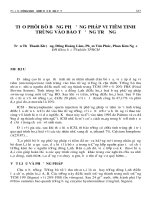
In figure 1, we can see the sphere tip punch
that is mounted in the spindle ofa CNC milling
machine. To consider the absolute rigidity of
the spindle and the carriage machine, their
deformations, if exist, are infinitesimal, the
deformation of the punch can be divided in 3
sections:
= Section 1: the deformation of the sphere
surface of the tangent area (y;) is equal to the
depth t of feeding rate.
=
Section 2: a part of phere area (y>) of the
length of D/2-t that has a variable section.
-
Section
3:
the
tail
of the
punch
to the
clamping area of length (ys)
pl
®
ID.2
oN
Ơ
Figure 1. Deformed sections of the punch
Figure 2. Calculating the deformation of the tangent
section |
Bản quyền thuộc ĐHQG-HCM
Trang 15
Science & Technology Development, Vol 13, No.K4- 2010
2.1.1. Calculating the deformed surface of
section 1 (the tangent area of punch and
sheet)
Although, the punch is made of by a very
hard material such as High Speed Steel,
Cutting tool alloy steel... It is deformed by the
elastic
and
deformation
causes
the
that
shorting
decreases
its length
dimensions
of the
tangent
not
been
interested
in
its
importance
and
Name:
D: diameter of the punch
-
t: the tangent depth
center
is
When applying on sheet, the punch
generates only the deformation on the radius of
the sphere but the circumference of the tangent
area is invariable. In figure 2 we can verify that
AC has a maximum value to AC’.
The elastic strain of the sheet is calculated
1
exactly #om the Ludwik formula: E = In(—)
0
At the position of an arbitrary angle =
(OB’, OC’), the deformation is the arc I=AB”
finding out the measurement to remedy.
-
at
(0na= 8TCCOS
product after unloaded and has an effective part
on the springback that the recent papers have
angle
when its initial value is l=AB.
Hence ¢ =j,/ _j,|_
Observing the plastic deformed area in the
tangent sphere sheet, we found that the plastic
deforming of the sheet in the tangent area is
proportional to the elastic deformation of the
sphere tool tip and it formed the reaction
Ð
DY Dt-t* -Dsing
Q)
-At point A (max) the strain sạ=0
-At top C’ of the punch (9=0) the strain is
be
stresses on the last.
The deforming area is a part of the sphere
of radius of D/2, with the depth oft and
1⁄2
=In
D arccos(.
2N
(
DI
D-2t
———
5
)
—¡?
Since the elastic deformation is caleulated by (1) we can apply Ludwid °s formula for calculating
the elastic stress at an arbitrary tangent angle @ on the sphere section of the sheet.
Trang 16
Bản quyền thuộc ĐHQG-HCM
TẠP CHÍ PHÁT TRIÊN KH&CN,
P@ ua =9)
ø =ke" =k.Ini—————®>—————
y
TẬP 13, SÓ K4 - 2010
(2)
Dy Dt-t? —Dsing
—Ing = In(k.e")
Inkt n.In(e) =In(k)+n.In | In(
D
_
Pm =?)
DVDt
—t*? —- Dsin 9
Formula (2) describes the elastic stress at
an arbitrary point in arbitrary tangent area of
sheet and punch. It has the same direction of
strain. This means
y"
The stress of the circumference direction
ø=0 due to the non deformation on
circumference.
it has tangent direction with
Let’s
consider
an
infinitesimal
the sphere at an arbitrary line that makes an
volume
angle @ (Figure 2) with the axe of the punch.
According to Von Mise critical, we write down
We can consider it the normal elastic stress in
the tangent direction o°
3 main orthogonal stresses of the cube. From
[7] we can find out the relationship among the
or kIn(
D
DVDt-
Prax
=
=)
—Dsing
yn
in the tangent
cube
area in figure 2.
@)
main stresses:
[€or 92)" + (G2- 63)" (63-61)
J!”
with o=or,
7
= oy=0 `
02= Gr,
O3= Gy=0 O5= `
(đ;-Ơy)
2
+On
2
2S
+O,
=
Og
2
+Oy
2
—O7OR
On? -GRGrs Gr? Y?=0
Condition A= ør- 4(ør”. Y?)= 4Y -3 67 >05 ơ„<
2
v3
Replace (3) into (4) we have the normal stress on the sheet surface and with the law of Newton III it
is also the normal stress on the spheral surface of the punch.
Bản quyền thuộc ĐHQG-HCM
Trang 17
Science & Technology Development, Vol 13, No.K4- 2010
|
. lve
ate
om =
\
DO
=
2VDt-P
2
9)
-Dsing
ces
]
6)
Select “+” sign and interest in the worst case that is the maximum stress: it appears at the top C’ of
the punch (@=0)
mac E
i
co
Pris
Jin he,
2vDt—
i
ANDI =
2
D-2t
In figure 2 Pyar = 7
Hence GMa=
|
wf
D-2t
+ [4° -3k of Par)
\
2jDi~r
2
m
(6)
The tangent strain is s= on/Ep, where Ep is Young’s modulus of the punch
] +ự
vui
Beano)
2JjDi=t#—Dsinp
2E,
2E,
From (6) we can calculate the maximum strain at the top of the punch (at =0)
_
D-2t
k,n] =]
(5
E Max =
"
]
[
2a ( —D=2t
+ Jay? vi -3k°In)
a
\
2E
>
eo
2m
)
The tangent depth is t (Figure 2), we can calculate the displacement of the shorted dimension at
tangent area y¡=t.Eax:
k.In]
D-2t
(a
—————————
of
D
t
| +, /4Y? -3k*In] ———
{
(a
2E, p
@)
2.1.2. Elastic deformation of the volume of the cantileyer part of the punch y;:
By the cantilever clamped section, this part of the punch is also pressed.
With its diameter D and the length L of the punch the pressed deformation is calculated as:
Trang 18
Bản quyền thuộc ĐHQG-HCM
TẠP CHÍ PHÁT TRIÊN KH&CN,
Bays
TẬP 13, SĨ K4 - 2010
rVD-P
Jor. cos B.ds = Jon cos B.ds = Jon cos B.2ardr
Calculate its maximum value when op reaches its critical value in (6)
: mal
ZMaxs =~
s...'s.Í-(cš]
aD?
2ry’
Replace (6) into:
r2”
D-
Pate == | kf Pare
12
pm
(8)
\
The shorted pressed displacement y, in Z direction [7] is
+fav? 23k? HỆ
\
(9)
Bản quyền thuộc ĐHQG-HCM
Trang 19
Science & Technology Development, Vol 13, No.K4- 2010
2.1.3. Calculating the strain y, on the surface of section 2 (the area that is not contacted to the
sheet).
From the figure 2, equation of the profile x” + y
=——
The horizontal radius in tangent area changes in [-(D/2-t),0]
2
4
Area of this section 4 , =a? =2(2_TO y?)
Dis-placement du in differential axial dy:
du — Pesta Y
E,A,
Total displacement is:
y= Pa
TE,
J[
dy
D
D
=-4Pru
hiên °Œ<=#~3)
xDE,
J[
Pol
D
1
+
Gy
D
1
ldy
Gt»
0
;
——
Pa,
aD(D ~t)E,
(10)
12(D-~¡)E,
2.1.4. Total strain due by the elastic of the punch y,= y1s Yas ¥s
From (7), (9) and (10) we can calculate the total strain of the punch:
Trang 20
Bản quyền thuộc ĐHQG-HCM
TẠP CHÍ PHÁT TRIÊN KH&CN,
Dat)
2
”
ay
|
+ Jay? -3ieinf 2
{
2
TẬP 13, SĨ K4 - 2010
>
12(D-1
] sư
-kh
2E,
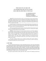
2.2. Deformation generated by the sinking of
the sheet when forming:
The maximum axial resultant Pzm can
cause the sinking of the sheet. Let’s observe
figure 3 with the simple clamping plate (round
in general case) but the shape of the sheet is
more complex. Lya: is
from the gutter of the
minimum radius of the
extracted from the
the maximum distance
clamping plate to the
sheet. The sinking is
result 8-4 of [6]
Parc Max A, Ly Max
8,1,
Replace (8) into it:
| “(1-2 fate
AN
d2)
Figure 3: The sinking of the clamping plate and the rigidity of the carriage of the machine
2.3. The sinking due by the flexib
clamping plate
Bản quyền thuộc ĐHQG-HCM
of the
In figure 3 we can see the pressed part of
the clamping plate yg:
Trang 21
Science & Technology Development, Vol 13, No.K4- 2010
- The down clamping plate that is restricted
by the square boundary with its side a and the
diameter $ of upward clamping plate with a
round hole inside ( in the experimental
condition a=310 and ÿ=250)
Eg is the Young’s modulus of the clamping
plates, we can calculate it as the following
value:
- The foundation (Figure3) is composed of
2 C section steel bar. Name Ag is its section
(Ag= 5*310=1550mm”) and lg is its height (Ig=
200mm)
Yq = Đo
AE
on
+,|4Y? -3kIn|
nD") kl
\
Ye =
(13)
2
24A,.Eu
2.4, Total compensation:
Addition all the values in (11), (12), and (13) we get the total compensation:
3s =J; TJr + VG
D-2t
Ễ Dt-t
yy =| k.In) ————]
-
2t
1+|—-1
D
Py
HT
)
|
ra2
+. ]4y? -se'n{ Pam
\
2VDt
t.D
stro
oT
3E„
12(D-¡)E,
3. CONCLUSION
By mean of analyzing, the paper could
provides the total compensation due by elastic
deformations of the punch, sheet, and clamping
installations. In the experiment with material
such as aluminum A 1050 H14, the concrete
parameters such as D=l0mm, t=3mm,
L=70mm... with the application of equation
Trang 22
A,
tt oo
96E,,
âm
|
(14)
De | it
ee!
|
(14) we can get the total compensation value
ys=2,73945mm. It is a too big value that shows
us the importance of springback after forming
which
could
dimensions.
described
interfere
In
in
fact,
this
the
errors
all calculations
paper
compensation
in practice
the
software
specific
to
will
by
the
be
of
that are
used
for
interfere
into
Pro/Engineer
in the
future.
Bản quyền thuộc ĐHQG-HCM
TẠP CHÍ PHÁT TRIÊN KH&CN,
TẬP 13, SĨ K4 - 2010
TÍNH TỐN BÙ TRỪ HIỆN TƯỢNG CO GIÃN KÍCH THƯỚC
KHI TẠO HÌNH TÁM BẰNG PHƯƠNG PHÁP SPIF
Nguyễn Thanh Nam”, Võ Văn Cương”), Lê Khánh Điền®, Lê Văn Sỹ“
(1)PTN Trọng điểm Quốc gia Điều khiển số và Kỹ thuật hệ thống, ĐHQG-HCM
(2) Trường Đại học Bách Khoa, ĐHQG-HCM
(3) Dai hoc Padova, Y
TÓM
TẤT:
Vấn đề bù trừ
sai số kích thước thành phẩm gây ra do hiện tượng co giãn
(Springback) sau khi tạo hình tắm kim loại bằng phương pháp SPIF (Single Poin Incremental
Forming) hiện đang là một trong những thách thức mà các nhà nghiên cứu công nghệ SPIF trên thế
giới đang quan tâm và tìm cách giải quyết [1]. Bài báo này chỉ là một đề nghị nhỏ dựa trên phân tích
giải tích vĩ mơ mơ hình gia cơng biến dạng dẻo tắm bằng phương pháp SPIF để đưa ra lượng bù dao
hợp lý mà các nghiên cứu hiện nay chưa quan tâm đến:
- Xem phơi tắm chịu biến dạng đàn dẻo cịn chày có đâu hình câu có biến dạng đàn hơi nhằm bù
trừ cho biến dạng đàn hồi của chày.
- Tắm được kẹp chặt
với liên kết ngàm có độ võng tại nơi chày ép tạo hình cũng được tính tốn
để đưa vào lượng bù trừ đơng thời bài viễt cũng tính tốn giới hạn lực tạo hình do các thơng số gia
cơng sao cho vùng lún của tắm cịn nằm trong giới hạn đàn hồi và phục hồi trở lại sau khi tháo lực
nhằm triệt tiêu sai số hình dáng phụ do hiện tượng dẻo khơng mong muốn.
Với 2 đóng góp nhỏ bé nhưng mới mẻ trên, bài toán lý thuyết dẻo trong tạo hình tắm được tiến
gân hơn nữa với mơ hình thật của một cơng nghệ gia cơng tắm hiện cịn rất mới tại nước ta.
Từ khóa: phương phdp SPIF, tạo hình tắm
Conference on Computational Plasticity,
REFERENCES
CIMNE, Barcelona, 2005.
[1]. Edward Leszak, “Apparatus and Process
[3]. L. W. Meyer, C. Gahlert and F. Hahn,
for Incremental Dieless Forming”, Ser.No.
“Influence of an incremental deformation
on material behavior and forming limit of
aluminum A 199,5 and QT-steel 42crmo4”,
388.577 10 Claims (Cl. 72- 81)
[2].G.
Ambrogio,
L. Filice, F. Gagliardi,
“Three-dimensional
FE
simulation
of
single
point
incremental
forming:
experimental evidences and process design
improving”,
The
VIII _ International
Bản quyền thuộc ĐHQG-HCM
Advanced Materials Research (2005) pp
417-424
[4]. J. Jeswiet, D. Young and M. Ham
“Non-
Traditional Forming Limit Diagrams for
Trang 23
Science & Technology Development, Vol 13, No.K4- 2010
Incremental Forming” Advanced Materials
Research Vols. 6-8 (2005) pp 409-416
[7]. Jacob
Lubliner,
Plasticity
Theory,
Macmillan Publishing, New York (1990).
[5]. J. Jeswiet “Asymmetric Incremental Sheet
Forming” Advanced Materials Research
Vols. 6-8 (2005) pp 35-38.
[8]. Nguyen Luong Dung, “Bien dang kim
loai”, DHBK, 1993.
[6]. Tasmania Lecture notes “Structure and
Mechanics” ACC213, UTAS 2002, pp 8-4
Trang 24
Bản quyền thuộc ĐHQG-HCM