Tài liệu 01-09 Installing and Routing the Cables ppt
Bạn đang xem bản rút gọn của tài liệu. Xem và tải ngay bản đầy đủ của tài liệu tại đây (1.53 MB, 63 trang )
OptiX OSN 3500
Installation Manual Contents
Contents
9 Installing and Routing the Cables 1
9.1 Installing and Routing the Power Cables 2
9.1.1 Connection of the Power Cables 2
9.1.2 Procedure for Upward Cabling 7
9.1.3 Procedure for Downward Cabling 9
9.1.4 Check Points 11
9.2 Installing and Routing the Indicator Cables 12
9.2.1 Connection of the Indicator Cables 12
9.2.2 Installing the Indicator Cables 14
9.3 Installing and Routing the Alarm Cables 15
9.3.1 Connection of the Alarm Cables 15
9.3.2 Procedure for Upward Cabling 18
9.3.3 Procedure for Downward Cabling 20
9.4 Installing and Routing E1/T1 Cables 22
9.4.1 E1/T1 Cables and Interface Boards 22
9.4.2 Procedure for Upward Cabling 27
9.4.3 Procedure for Downward Cabling 30
9.5 Installing and Routing E3/T3/E4/STM-1 Cables 33
9.5.1 E3/T3/E4/STM-1 Cables and Interface Boards 33
9.5.2 Procedure for Upward Cabling 34
9.5.3 Procedure for Downward Cabling 36
9.6 Installing and Routing Ethernet Cables 38
9.6.1 Ethernet Cables and Interface Board 38
9.6.2 Procedure for Upward Cabling 39
9.6.3 Procedure for Downward Cabling 41
9.7 Installing and Routing External Clock Cables 43
9.7.1 Clock Cables and Interfaces 43
9.7.2 Procedure for Upward Cabling 45
9.7.3 Procedure for Downward Cabling 47
9.8 Installing and Routing Network Cables 49
9.8.1 Network Cables and Interfaces 49
Issue 05 (2006-11-20)
Huawei Technologies Proprietary
i
Contents
OptiX OSN 3500
Installation Manual
7.1.1 Procedure for Upward Cabling 50
9.8.2 Procedure for Downward Cabling 52
9.9 Installing and Routing Extended Subrack Cables 54
9.9.1 Connection of the Extended Subrack Cables 54
9.9.2 Connecting the Main Subrack with the Extended Subrack 57
9.10 Checking the Cable Installation 59
ii
Huawei Technologies Proprietary
Issue 05 (2006-11-20)
OptiX OSN 3500
Installation Manual Figures
Figures
Connection of the power cables and PGND cable 3
Panel of the power distribution unit 4
Connecting the PGND cable to the grounding bolt 5
Connecting the PGND cable to the two grounding bolts 6
Connecting the PGND cable to the power distribution unit 6
Torque spanner 7
Downward cabling power cables and PGND cable 10
Connection of the indicator cables 12
Indicator interfaces 13
Connection of the alarm output cables 15
Connection of the input cables 16
Alarm interfaces on the AUX board 17
Upward cabling mode for alarm cables 19
Downward cabling mode for alarm cables 21
E1 cables 22
E1 electrical interface boards 26
Routing the E1 cables into the cabinet 27
Sequence of upward installing E1 cables to a board 28
Sequence of installing E1 cables for the upper subrack 28
Upward cabling mode for E1 cables 29
Sequence of upward installing E1 cables to a board 31
Issue 05 (2006-11-20)
Huawei Technologies Proprietary
iii
Figures
OptiX OSN 3500
Installation Manual
Sequence of installing E1 cables of boards 31
Downward cabling mode for E1 cables 32
SMB coaxial connector of the E3/T3/E4/STM-1 cable 33
E3/T3/T4/STM-1 interface boards 33
Upward cabling mode for E3/T3/E4/STM-1 cables 35
Downward cabling mode for E3/T3/E4/STM-1 cables 37
Connectors of Ethernet cables 38
Ethernet electrical interface boards 39
Upward cabling mode for Ethernet cables 40
Downward cabling mode for Ethernet cables 42
External clock cables and clock transit cables 43
External clock interfaces of AUX board 44
Upward cabling mode for external clock cables 46
Upward cabling mode for external clock cables 48
Straight-through or crossover network cable 49
Management interfaces on the AUX board 49
Upward cabling mode for network cables 51
Downward cabling mode for network cables 53
Connection of the extended subrack cables 55
Extended subrack cables 56
Extended subrack interfaces 57
iv
Huawei Technologies Proprietary
Issue 05 (2006-11-20)
OptiX OSN 3500
Installation Manual Tables
Tables
Figure 1.1Colors and types of external power cables and PGND cable 4
Table 1.1Ways to connect the PGND cable to the cabinet 5
Figure 1.1Pin assignment of LAMP1 and LAMP2 interface 13
Figure 1.1Description of the alarm interfaces 17
Table 1.1Pin assignment of the 75-ohm E1 cables 23
Table 1.2Pin assignment of the 120-ohm E1 cable 25
Figure 1.1Pin assignment of 120-ohm external clock cable 44
Issue 05 (2006-11-20)
Huawei Technologies Proprietary
v
OptiX OSN 3500
Installation Manual 9 Installing and Routing the Cables
9 Installing and Routing the Cables
About This Chapter
Note
Before installing cables, remove the side doors and the front door. Install the side
doors and the front door after installing all cables and fibers. Refer to Chapter 12
"Installing the Doors of the Cabinet".
This chapter describes how to install and route cables. The cables of the OptiX
OSN 3500 are divided into internal cables and external cables.
Internal cables are used for connecting electrical interfaces in one cabinet. They
have been installed or routed in the cabinet before shipment and delivered
together with the cabinet.
External cables are used for connecting electrical interfaces of one cabinet with
those of other cabinets or peripherals.
The following table lists the contents of this chapter.
Section Description
9.1Installing and Routing the
Power Cables
Describes how to install and route power cables.
9.2Installing and Routing the
Indicator Cables
Describes how to install and route cabinet
indicator cables.
9.3Installing and Routing the
Alarm Cables
Describes how to install and route alarm cables.
Issue 05 (2006-11-20)
Huawei Technologies Proprietary
1
9 Installing and Routing the Cables
OptiX OSN 3500
Installation Manual
Section Description
9.4Installing and Routing E1/T1
Cables
Describes how to install and route E1/T1 cables.
9.5Installing and Routing
E3/T3/E4/STM-1 Cables
Describes how to install and route
E3/T/3E4/STM-1 cables.
9.6Installing and Routing Ethernet
Cables
Describes how to install and route Ethernet
cables.
9.7Installing and Routing External
Clock Cables
Describes how to install and route clock cables.
9.8Installing and Routing Network
Cables
Describes how to install and route the network
cables.
9.9Installing and Routing Extended
Subrack Cables
Describes how to install and route the extended
subrack cables.
9.10Checking the Cable
Installation
Describes the check points of cable installation.
9.1 Installing and Routing the Power Cables
This section describes how to install and route the power cables.
9.1.1 Connection of the Power Cables
Power cables are divided into cabinet power cables and subrack power cables. The
subrack power cables have been connected to the power distribution unit at
delivery.
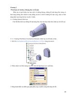
Figure 1.1 shows the connection of the power cables.
2
Huawei Technologies Proprietary
Issue 05 (2006-11-20)
OptiX OSN 3500
Installation Manual 9 Installing and Routing the Cables
Optix OSN3500
Optix OSN3500
Office ground
A
A
1
2
3 4
1
2
3 4
Office power supply
-48 V -48 V
0 V 0 V
Figure 1.1 Connection of the power cables and PGND cable
Power Distribution Unit
The DC power distribution unit is located on the top of the cabinet and connected
to the external power supply.
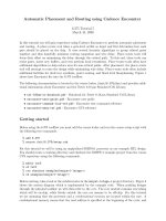
Figure 1.2 shows the panel of the power distribution unit.
Issue 05 (2006-11-20)
Huawei Technologies Proprietary
3
9 Installing and Routing the Cables
OptiX OSN 3500
Installation Manual
NEG2(-)
INPUT
RTN2(+)
RTN1(+) NEG1(-)
2 3 4 5
ON
OFF
20A32A 32A
20A
ON
OFF
1
2
3
4
1 6
1
2
3
4
20A32A 32A
20A
OUTPUT
OUTPUT
A
B
1. Power socket (left) 2. Power cable RTN1(+) 3. Power cable RTN2(+)
4. Power cable NEG1(–) 5. Power cable NEG2(–) 6. Power socket (right)
Figure 1.2 Panel of the power distribution unit
RNT1(+) and NEG1(-) supply power for the left four sockets. RNT2(+) and
NEG2(-) supply power for the right four sockets.
Generally the OptiX OSN 3500 uses sockets 1 and 2. Sockets 3 and 4 are used for
power supply of other equipment in the cabinet.
Power Cables and PGND Cable
Figure 1.1 describes the colors and types of power cables and PGND cable. The
PGND cable and power cable between the cabinet and the power supply
equipment have no roundabout twists or turns.
Figure 1.1 Colors and types of external power cables and PGND cable
Cable type Polarity Color
DC power cable NEG (–48 VDC) Blue
RTN (BGND) Black
PGND cable PE (PGND) Yellow and green
4
Huawei Technologies Proprietary
Issue 05 (2006-11-20)
OptiX OSN 3500
Installation Manual 9 Installing and Routing the Cables
Cabinet Grounding
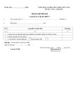
Table 1.1 lists three options to connect the PGND cable to the cabinet.
Table 1.1 Ways to connect the PGND cable to the cabinet
PGND cable
connector
Grounding bolt on the top
of the cabinet
Ways to connect the PGND cable
M8 One M8 grounding bolt Connect the PGND cable to the M8
grounding bolt on the top of the
cabinet. See Figure 1.3.
Two M8 grounding bolts Connect the PGND cable to the M8
grounding bolts on the top of the
cabinet. See Figure 1.4.
M6 - Remove the internal PGND cable from
the power distribution unit first.
Connect the PGND cable to the power
distribution unit.
Connect the internal PGND cable back
to the power distribution unit.
See Figure 1.5.
Power cable and
PGND cable
Grounding
bolt
PGND
cable
Figure 1.3 Connecting the PGND cable to the grounding bolt
Issue 05 (2006-11-20)
Huawei Technologies Proprietary
5
9 Installing and Routing the Cables
OptiX OSN 3500
Installation Manual
Power cable and
PGND cable
Figure 1.4 Connecting the PGND cable to the two grounding bolts
Power cables and
PGND cable
PGND cable
Internal PGND cable
power distribution
unit
Figure 1.5 Connecting the PGND cable to the power distribution unit
6
Huawei Technologies Proprietary
Issue 05 (2006-11-20)
OptiX OSN 3500
Installation Manual 9 Installing and Routing the Cables
Caution
A M6 torque spanner is required to fasten external power cables during field
installation. The force moment shall be controlled with the range of 4 ±0.5 Nm.
Otherwise, the screw thread may be broken which then may cause unreliable
connection. If there is no torque spanner, do use the socket wrench as described in
Figure 1.6 to fasten the cables to ensure a reliable connection. When the cable is
fastened to such an extent that the spring washer is flattened, do not fasten it
further. Otherwise, the bolt may be broken.
Figure 1.6 Torque spanner
9.1.2 Procedure for Upward Cabling
Purpose
This procedrue guides you to connect the power cables to
the power distribution unit from the top the cabinet.
Tools/Materials
Cross screwdriver
Power cable
PGND cable
Wire cutter
Wire stripper
Crimp tool
Prerequisites
The office power supply is prepared.
The voltage ranges from –38.4 V DC to –72 V DC.
Required/As needed
Required if the power cables are upward cabled.
Caution
It is forbidden to install or demount the power cable while the power is on. Do
turn off the power switch before such operations to avoid personal injuries.
Issue 05 (2006-11-20)
Huawei Technologies Proprietary
7
9 Installing and Routing the Cables
OptiX OSN 3500
Installation Manual
Caution
The signal cable, power cable and fiber jumper shall be routed and bundled
separately, with a spacing of more than 3 cm between each other.
Step 1 Measure and cut the cables as needed to reach the OptiX OSN 3500 from the
office power supply.
Step 2 Attach temporary labels to both ends of the cables.
Step 3 Install appropriate connectors at both ends of each cable. When installing the
connector, connect it firmly with the cable and equip it with a heat-shrink tube so
as not to expose the bare core and the handle of the connector.
Step 4 Route the power cables to the power distribution unit through the power cable
hole on the top of the cabinet.
Step 5 Route and connect the PGND cable to the cabinet. See Table 1.1.
Step 6 Connect the PGND cable to the office ground.
Step 7 Respectively insert the cord end terminals of the -48V cables and 0V cables into
the sockets for them. A recommended order is RTN1(+), RTN2(+), NEG1(–), and
NEG2(–). Then tighten the screws with a screwdriver.
Step 8 Measure the resistance between NEG1(–) and RTN1(+), and the resistance
between NEG2(–) and RTN2(+). If the resistance is less than 20 ohm, it indicates
there is a short circuit. Find out the causes and install the cables again.
Step 9 Measure the resistance between NEG1(–) and PGND, and the resistance between
NEG2(–) and PGND. If the resistance is less than 20 ohm, it indicates there is a
short circuit. Find out the causes and install the cables again.
Step 10 Remove the temporary labels and bind the cable ties of the identification plates 2
cm away from the connectors of the cables.
Step 11 Connect the power cables to the office power supply.
Step 12 Connect the subrack power cables to the PIU boards
End
8
Huawei Technologies Proprietary
Issue 05 (2006-11-20)
OptiX OSN 3500
Installation Manual 9 Installing and Routing the Cables
9.1.3 Procedure for Downward Cabling
Purpose
This procedrue guides you to connect the power cables to
the power distribution unit from the bottom the cabinet.
Tools/Materials
Cross screwdriver
Power cable
PGND cable
Wire cutter
Wire stripper
Crimp tool
Prerequisites
The office power supply is prepared.
The voltage ranges from –38.4 V DC to –72 V DC.
Required/As needed
Required if the power cables are downward cabled.
Caution
It is forbidden to install or demount the power cable while power is on. Do turn
off the power switch before such operations to avoid personal injuries.
Caution
The signal cable, power cable and fiber jumper shall be routed and bundled
separately, with a spacing of more than 3 cm between each other.
Step 1 Measure and cut the cables as needed to reach the OptiX OSN 3500 from the
office power supply.
Step 2 Attach temporary labels to both ends of the cables.
Step 3 Install appropriate connectors at both ends of each cable. When installing the
connector, connect it firmly with the cable and equip it with a heat-shrink tube so
as not to expose the bare core and the handle of the connector.
Step 4 Pass the power cables and the PGND cable through the cabling hole at the bottom
of the cabinet. See Step 5Figure 1.1.
Step 5 Route the PGND cable and RTN(+) cable to the left and route the NEG(-) power
cable to the right, and then put them separately into the cabling trough of the
column behind the cabinet. See Figure 1.1
Issue 05 (2006-11-20)
Huawei Technologies Proprietary
9
9 Installing and Routing the Cables
OptiX OSN 3500
Installation Manual
Cabling
tough
Power distribution
box
Power
cable
Cabinet
Figure 1.1 Downward cabling power cables and PGND cable
Note
There is one or two cabinet grounding bolts on one cabinet. The above figure is
displayed only for reference. For details, see Table 1.1.
Step 6 Route those cables up to the power distribution unit.
Step 7 Connect the two-hole lug of the PGND cable to the grounding bolt. Fasten the
nuts with socket wrench. Do not exert too much strength. Just press the spring
washer flattened.
Step 8 Respectively insert the cord end terminals of the -48V cables and 0V cables into
the sockets for them. A recommended order is RTN1(+), RTN2(+), NEG1(–), and
10
Huawei Technologies Proprietary
Issue 05 (2006-11-20)
OptiX OSN 3500
Installation Manual 9 Installing and Routing the Cables
NEG2 (–). Then tighten the screws by screwdriver.
Step 9 Measure the resistance between NEG1(–) and RTN1(+), and the resistance
between NEG2(–) and RTN2(+). If the resistance is less than 20 ohm, it indicates
a short circuit. Find out the causes and install the cables again.
Step 10 Measure the resistance between NEG1(–) and PGND, and the resistance between
NEG2(–) and PGND. If the resistance is less than 20 ohm, it indicates there is a
short circuit. Find out the causes and install the cables again.
Step 11 Remove the temporary labels and bind the cable ties of the identification plates 2
cm away from the connectors of the cables. Fill in the cable labels referring to
"Appendix D Engineering Labels for Cables".
Step 12 Connect the power cables to the office power supply. See 9.1.1 I. I. Step 1Figure
1.1.
Step 13 Connect the subrack power cables to the PIU boards. See 9.1.1 I. I. Step 1Figure
1.1.
End
9.1.4 Check Points
Check the installation with the following items.
The connectors of the power cable and PGND cable are fixed firmly and
connected reliably.
The contents on the cable label are consistent with those in design.
The PGND cable and power cable between the cabinet and the power supply
equipment have no roundabout twists or turns.
Issue 05 (2006-11-20)
Huawei Technologies Proprietary
11
9 Installing and Routing the Cables
OptiX OSN 3500
Installation Manual
9.2 Installing and Routing the Indicator Cables
This section describes how to install and route the indicator cables between the
subrack and the cabinet indicators.
9.2.1 Connection of the Indicator Cables
There are four indicators on the top of the cabinet. The cabinet indicators are
driven by subrack, so you should connect the cable properly and power on the
subrack first. The indicator cables have been installed before delivery.
Figure 1.1 shows the connection of the indicator cables.
OptiX OSN3500
OptiX OSN3500
A
Power distribution unit
Indicator cable
Indicator concatenating cable
B
PHONE V1 V2 OAM
ALMO2ALMO1LAMP2LAMP1
B
A
PHONE V1 V2 OAM
ALMO2ALMO1LAMP2LAMP1
to the upper subrack
to cabinet indicators
Figure 1.1 Connection of the indicator cables
12
Huawei Technologies Proprietary
Issue 05 (2006-11-20)
OptiX OSN 3500
Installation Manual 9 Installing and Routing the Cables
Indicator Interfaces
The indicator interfaces are on the AUX board. Figure 1.2 shows the indicator
interfaces.
AUX boardIndicator interface
CLKI1
STAT
S1 S2 S3 S4CLK1 REV F&f F1 PHONE V1 V2 OAM
CLKI2
CLKO1 CLKO2
ALMI3 ALMI4ALMI2ALMI1ALMO2ALMO1LAMP2LAMP1EXTCOMETHCLK2
A U X
A U X
Indicator concatenating interface
Figure 1.2 Indicator interfaces
Figure 1.1 Pin assignment of LAMP1 and LAMP2 interface
Front view Pin No. Description
8 7 6 5 4 3 2 1
1 The positive of critical alarm signal
2 The negative of critical alarm signal
3 The positive of major alarm signal
4 The positive of power indicator signal
5 The negative of power indicator signal
6 The negative of major alarm signal
7 The positive of minor alarm signal
8 The negative of minor alarm signal
Issue 05 (2006-11-20)
Huawei Technologies Proprietary
13
9 Installing and Routing the Cables
OptiX OSN 3500
Installation Manual
9.2.2 Installing the Indicator Cables
Purpose
This procedrue guides you to connect the indiator cables
between the indicators and the interfaces on the AUX
board.
Tools/Materials
Indicator cable
Indicator concatenating cable
Prerequisites
The cabinet and the subrack have been installed.
Required/As needed
Required
Caution
Use the indicator cables. Do not install other cables in the indicator interface.
Caution
Be sure there is no particulate contamination in the indicator interface before
powering on the subrack.
Step 1 Connect the indicator cable between the indicators and the "LAMP1" interface on
the AUX board of the lower subrack. See 9.2.1 I. I. Step 1Figure 1.1.
Step 2 Connect the indicator concatenating cable between the "LAMP1" interface on the
upper subrack and the "LAMP2" interface on the lower subrack. See 9.2.1 I. I.
Step 1Figure 1.1.
Step 3 Attach the cable labels 2 cm away from the connectors at the two ends and fill in
the cable labels referring to Appendix D "Engineering Labels for Cables".
End
14
Huawei Technologies Proprietary
Issue 05 (2006-11-20)
OptiX OSN 3500
Installation Manual 9 Installing and Routing the Cables
9.3 Installing and Routing the Alarm Cables
This section describes how to install and route the alarm cables.
9.3.1 Connection of the Alarm Cables
The OptiX OSN 3500 provides 16 alarm inputs and 4 alarm outputs through the
AUX board.
Connection of the Alarm Output Cables
Figure 1.1 shows the connection of the alarm output cables. If critical alarms or
major alarms occur in one of subracks, indicators on the alarm monitor will be on.
cabinet 1 Cabinet 2
Upper subrack Lower subrack
CLKI1
STAT
S1 S2 S3 S4CLK1 REV F&f F1 PHONE V1 V2 OAM
CLKI2
CLKO1 CLKO2
ALMI3 ALMI4ALMI2ALMI1ALMO2ALMO1ALMP2ALMP1EXTCOMETHCLK2
A U X
A U X
CLKI1
STAT
S1 S2 S3 S4CLK1 REV F&f F1 PHONE V1 V2 OAM
CLKI2
CLKO1 CLKO2
ALMI3 ALMI4ALMI2ALMI1ALMO2ALMO1ALMP2ALMP1EXTCOMETHCLK2
A U X
A U X
CLKI1
STAT
S1 S2 S3 S4CLK1 REV F&f F1 PHONE V1 V2 OAM
CLKI2
CLKO1 CLKO2
ALMI3 ALMI4ALMI2ALMI1ALMO2ALMO1ALMP2ALMP1EXTCOMETHCLK2
A U X
A U X
CLKI1
STAT
S1 S2 S3 S4CLK1 REV F&f F1 PHONE V1 V2 OAM
CLKI2
CLKO1 CLKO2
ALMI3 ALMI4ALMI2ALMI1ALMO2ALMO1ALMP2ALMP1EXTCOMETHCLK2
A U X
A U X
Upper subrack Lower subrack
To alarm
monitor
Figure 1.1 Connection of the alarm output cables
Issue 05 (2006-11-20)
Huawei Technologies Proprietary
15
9 Installing and Routing the Cables
OptiX OSN 3500
Installation Manual
Connection of the Alarm Input Cables
Figure 1.2 shows the connection of the alarm input cables. If the alarm collection
module detects a temperature alarm or any other alarm, the management system
reports the alarm.
Power distribution unit
OptiX OSN3500
Management sytstem
Alarm collection module
Temperature
sensor
Smoke
sensor
Water
sensor
Figure 1.2 Connection of the input cables
16
Huawei Technologies Proprietary
Issue 05 (2006-11-20)
OptiX OSN 3500
Installation Manual 9 Installing and Routing the Cables
Alarm Interfaces
Figure 1.3 shows the alarm interfaces on the AUX board. Figure 1.1 shows the
description of the alarm interfaces.
AUX board
Alarm output interface (ALMO1 and ALMO2)
CLKI1
STAT
S1 S2 S3 S4CLK1 REV F&f F1 PHONE V1 V2 OAM
CLKI2
CLKO1 CLKO2
ALMI3 ALMI4ALMI2ALMI1ALMO2ALMO1ALMP2ALMP1EXTCOMETHCLK2
A U X
A U X
PIN
1
2
5
4
3
6
7
8
FUNCTION
The positive of critical and major alarm output
The negative of cirtical and major alarm output
The positivie of minor and warning alarm output
The positive of alarm 1 output
The negative of alarm 1 output
The negative of minor and warning alarm output
The positive of alarm 2 output
The negative of alarm 2 output
Alarm input interface (ALMI1~ALMI4)
PIN
1
2
5
4
3
6
7
8
FUNCTION
Alarm input 1
The ground of alarm input 1
Alarm input 2
Alarm input 3
The ground of alarm input 3
The ground of alarm input 2
Alarm input 4
The ground of alarm input 4
Figure 1.3 Alarm interfaces on the AUX board
Figure 1.1 Description of the alarm interfaces
Alarm interfaces Description
ALMO1 House-keeping alarm concatenating interface
ALMO2 1–4 house-keeping alarm output interface
ALMI1 1–4 house-keeping alarm input interface
ALMI2 5–8 house-keeping alarm input interface
ALMI3 9–12 house-keeping alarm input interface
ALMI4 13–16 house-keeping alarm input interface
Issue 05 (2006-11-20)
Huawei Technologies Proprietary
17
9 Installing and Routing the Cables
OptiX OSN 3500
Installation Manual
9.3.2 Procedure for Upward Cabling
Purpose
This procedrue guides you to connect the alarm cables
from the top of the cabinet.
Tools/Materials
Alarm outout cable
Alarm input cable
Alarm cascading cable
Prerequisites
The alarm monitor of the equipment room has been
installed properly, with interfaces reserved for use.
The alarm collection module has been installed properly.
Required/As needed
Required if there are alarm signal needed to input or
output.
Step 1 Measure and cut the alarm cables according to the cabling route between the
cabinet and the alarm monitor.
Step 2 Attach temporary labels to both ends of the cables.
Step 3 Pass the alarm cables through the cabling holes on the top of the cabinet.
Step 4 Route them downward along the side of the cabinet to the cable distribution plate
above the subrack.
Step 5 Pass the alarm cables through the cable distribution plate and connect the cable
connectors to the corresponding interfaces on the AUX board. See Figure 1.1.
18
Huawei Technologies Proprietary
Issue 05 (2006-11-20)
OptiX OSN 3500
Installation Manual 9 Installing and Routing the Cables
alarm cable
AUX board
Upper
subrack
Figure 1.1 Upward cabling mode for alarm cables
Step 6 Bundle them with cable ties.
Step 7 Remove the temporary labels on the cable.
Step 8 Fill in the cable labels referring to Appendix D "Engineering Labels for Cables".
Step 9 Attach the cable labels 2 cm away from the connectors at the two ends. The text
area of the label should be right to or below the cable, facing towards you.
End
Issue 05 (2006-11-20)
Huawei Technologies Proprietary
19
9 Installing and Routing the Cables
OptiX OSN 3500
Installation Manual
9.3.3 Procedure for Downward Cabling
Purpose
This procedrue guides you to connect the alrms cables from
the bottom of the cabinet.
Tools/Materials
Alarm outout cable
Alarm input cable
Alarm cascading cable
Prerequisites
The alarm monitor of the equipment room has been
installed properly, with interfaces reserved for use.
The alarm collection module has been installed properly.
Required/As needed
Required if there are alarm signal needed to input or
output.
Step 1 Measure and cut the alarm cables according to the cabling route between the
cabinet and the alarm monitor.
Step 2 Attach temporary labels to both ends of the cables.
Step 3 Pass the alarm cables through the cabling holes at the bottom of the cabinet.
Step 4 Route them upward along the side of the cabinet to the cable distribution plate
above the subrack.
Step 5 Pass the alarm cables through the cable distribution plate and connect them to the
corresponding interfaces on the AUX board. See Figure 1.1.
20
Huawei Technologies Proprietary
Issue 05 (2006-11-20)