Tài liệu A Guide to Understanding Color Communication pdf
Bạn đang xem bản rút gọn của tài liệu. Xem và tải ngay bản đầy đủ của tài liệu tại đây (834.34 KB, 26 trang )
A Guide to
Understanding
Color
Communication
1
Communicating Color . . . . . . . . . . . . . . . . . . . . . . . . . . . . . . . . . . 2
Ways to Measure Color . . . . . . . . . . . . . . . . . . . . . . . . . . . . . . . . . 3
Integrated Color – Throughout the Supply Chain . . . . . . . . . . . 4-5
Applications . . . . . . . . . . . . . . . . . . . . . . . . . . . . . . . . . . . . . . . . . 6
Attributes of Color
Hue . . . . . . . . . . . . . . . . . . . . . . . . . . . . . . . . . . . . . . . . . . . . . . 7
Chroma . . . . . . . . . . . . . . . . . . . . . . . . . . . . . . . . . . . . . . . . . . . 7
Lightness. . . . . . . . . . . . . . . . . . . . . . . . . . . . . . . . . . . . . . . . . . 8
Scales for Measuring Color
The Munsell Scale. . . . . . . . . . . . . . . . . . . . . . . . . . . . . . . . . . . 9
CIE Color Systems . . . . . . . . . . . . . . . . . . . . . . . . . . . . . . . . 9-10
Chromaticity Values . . . . . . . . . . . . . . . . . . . . . . . . . . . . . . . . . 11
Expressing Colors Numerically
CIELAB (L*a*b*) . . . . . . . . . . . . . . . . . . . . . . . . . . . . . . . . . . . 12
CIELCH (L*C*h°) . . . . . . . . . . . . . . . . . . . . . . . . . . . . . . . . 12-13
Color Differences, Notation and Tolerancing
Delta CIELAB and CIELCH . . . . . . . . . . . . . . . . . . . . . . . . . . . 14
CIE Color Space Notation . . . . . . . . . . . . . . . . . . . . . . . . . . . . 15
Visual Color and Tolerancing . . . . . . . . . . . . . . . . . . . . . . . . . . 15
CIELAB Tolerancing. . . . . . . . . . . . . . . . . . . . . . . . . . . . . . . . . 15
CIELCH Tolerancing. . . . . . . . . . . . . . . . . . . . . . . . . . . . . . . . . 16
CMC Tolerancing . . . . . . . . . . . . . . . . . . . . . . . . . . . . . . . . 16-17
CIE94 Tolerancing . . . . . . . . . . . . . . . . . . . . . . . . . . . . . . . . . . 18
Visual Assessment vs. Instrumental . . . . . . . . . . . . . . . . . . . . . 18
Choosing the Right Tolerance . . . . . . . . . . . . . . . . . . . . . . . . . 18
Other Color Expressions
White and Yellow Indices . . . . . . . . . . . . . . . . . . . . . . . . . . . . . 19
Glossary . . . . . . . . . . . . . . . . . . . . . . . . . . . . . . . . . . . . . . . . . 20-24
Table of
Contents
© X-Rite, Incorporated 2002
2
How would you describe the color
of this rose? Would you say it’s
yellow, sort of lemon yellow or
maybe a bright canary yellow?
Your perception and interpretation
of color are highly subjective. Eye
fatigue, age and other physiolog-
ical factors can influence your
color perception.
But even without such physical
considerations, each observer
interprets color based on personal
references. Each person also
verbally defines an object’s color
differently.
As a result, objectively communi-
cating a particular color to
someone without some type of
standard is difficult. There also
must be a way to compare one
color to the next with accuracy.
The solution is a measuring instru-
ment that explicitly identifies a
color. That is, an instrument that
differentiates a color from all
others and assigns it a numeric
value.
Communicating
Color
3
Ways to
Measure Color
Today, the most commonly used
instruments for measuring color
are spectrophotometers.
Spectro technology measures
reflected or transmitted light at
many points on the visual spec-
trum, which results in a curve.
Since the curve of each color is as
unique as a signature or finger-
print, the curve is an excellent tool
for identifying, specifying and
matching color.
The following information can help
you to understand which type of
instrument is the best choice for
specific applications.
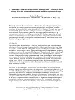
Spherical
Spherically based instruments
have played a major roll in formula-
tion systems for nearly 50 years.
Most are capable of including the
“specular component” (gloss) while
measuring. By opening a small
trap door in the sphere, the “spec-
ular component” is excluded from
the measurement. In most cases,
databases for color formulation are
more accurate when this compo-
nent is a part of the measurement.
Spheres are also the instrument of
choice when the sample is
textured, rough, or irregular or
approaches the brilliance of a first-
surface mirror. Textile manufac-
turers, makers of roofing tiles or
acoustic ceiling materials would all
likely select spheres as the right
tool for the job.
0/45 (or 45/0)
No instrument “sees” color more
like the human eye than the 0/45.
This simply is because a viewer
does everything in his or her power
to exclude the “specular compo-
nent” (gloss) when judging color.
When we look at pictures in a
glossy magazine, we arrange
ourselves so that the gloss does
not reflect back to the eye. A 0/45
instrument, more effectively than
any other, will remove gloss from
the measurement and measure the
appearance of the sample exactly
as the human eye would see it.
Multi-Angle
In the past 10 or so years, car
makers have experimented with
special effect colors. They use
special additives such as mica,
pearlescent materials, ground up
seashells, microscopically coated
colored pigments and interference
pigments to produce different
colors at different angles of view.
Large and expensive goniometers
were traditionally used to measure
these colors until X-Rite introduced
a battery-powered, hand-held,
multi-angle instrument. X-Rite
portable multi-angle instruments
are used by most auto makers and
their colorant supply chain, world-
wide.
Colorimeter
Colorimeters are not spectropho-
tometers. Colorimeters are tristim-
ulus (three-filtered) devices that
make use of red, green, and blue
filters that emulate the response of
the human eye to light and color. In
some quality control applications,
these tools represent the lowest
cost answer. Colorimeters cannot
compensate for metamerism (a
shift in the appearance of a
sample due to the light used to illu-
minate the surface). As colorime-
ters use a single type of light (such
as incandescent or pulsed xenon)
and because they do not record
the spectral reflectance of the
media, they cannot predict this
shift. Spectrophotometers can
compensate for this shift, making
spectrophotometers a superior
choice for accurate, repeatable
color measurement.
Sample Being Measured
Light Source
Receiver
Receiver
Sample Being Measured
Light
Source
15˚
25˚
45˚
75˚
110˚
45˚
45˚
Specular
Sample Being Measured
Sample
Viewing
Port
Specular
Port
Reference
Beam
Port
S
p
h
e
r
e
8˚
8˚
Spherical
0/45
Multi-angle
4
Integrated
Color –
Throughout the
Supply Chain
The instrumentation and communi-
cation of color data is as important
as the color data itself. Throughout
the supply chain, different
suppliers may use different
processes and equipment for color
formulation and quality assurance,
making compatibility an essential
component.
X-Rite products are designed for
integration and compatibility
throughout the supply chain. For
example a large installation may use
integrated, networked color formula-
tion and quality assurance software,
such as X-RiteColor
®
Master, and
several X-Rite sphere instruments
throughout the shop. A small
supplier with X-Rite QA-Master I
installed on a single computer and
one SP62 spectrophotometer will
be compatible with the larger
installation.
Color control is required in a wide
variety of applications, in varied
scopes. This is why X-Rite offers
the following process solutions:
Color Formulation and
Quality Assurance
From basic quality assurance
functions to the most sophisti-
cated color formulation needs,
X-RiteColor Master software,
combined with X-Rite instruments,
provides the ultimate flexibility to
scale software packages to unique
needs now and over time. Multiple
math engines can easily and accu-
rately formulate opaque, translu-
cent and transparent colors at
fixed loads or with minimized
pigment usage. With all databases
operating from the same structure
in a network installation, managing
color standards and measure-
ments makes X-RiteColor Master
the most efficient software for
enterprise and supply chain
processes.
Special Effect and
Pearlescent Paint
The X-Rite MA68II spectropho-
tometer offers a full range of
angular viewing (15˚ to 110˚) for
accurate evaluation of the changes
exhibited in metallic, pearlescent
and special effect paint finishes.
The unique dynamic rotational
sampling (DRS) technology utilizes
a simple, robust optical system
which provides simultaneous
measurement of all angles. The
MA68II interfaces with X-RiteColor
Master software for complete color
quality control applications.
Sphere and 0/45
Instruments
X-Rite offers a wide range of
sphere and 0/45 spectrophotome-
ters in portable and countertop
models that offer superb inter-
instrument agreement and
repeatability. These instruments
are easy to use and can be setup
for streamlined, automated capture
of color data.
Non-Contact Color
Measurement
The X-Rite TeleFlash system provides
online color measurement and evalua-
tion of color deviation to the running
production line. TeleFlash can accu-
rately measure the color of products
that are textured, finely patterned or glossy, such as extruded vinyl, bulk
goods, coil coatings, synthetic films, paints (wet and dry), textiles,
carpeting, granules, food pigments, paper, powders, glass, ceramics,
metal, minerals and plaster.
TeleFlash offers a measuring distance of up to five feet, tolerating small
variations in the measuring distance from system to sample. The system’s
thermochromism compensation allows for color measurement without the
time usually required for cooling and stabilizing.
Multi-User, Network Installations and Portable Data
The networkability of X-Rite software makes it easy to communicate data
and share standards across an enterprise. This ease translates into effi-
ciency which has a direct effect on profitability. For applications without
networked computers, X-Rite Color-Mail can be used for fast, easy
communication of color data via standard e-mail. ColorMail can be a
seamless part of X-RiteColor Master software.
Calibrated, On-Screen Color
X-Rite offers the only color formulation and quality assurance software to
use the International Color Consortium’s (ICC) standard device profiles for
on-screen color. This means that colors will be consistently displayed on
different computers, so long as ICC profiles are used. Use X-Rite monitor
optimizers and auto-scan densitometers for complete color calibration and
control on computers, printers and scanners.
Retail Color Matching Systems
MatchRite color matching systems are used worldwide in retail paint sales
and home decor services. With networkable installation, portable measure-
ment instruments and hundreds of available paint databases (plus the
ability to create new databases), MatchRite is the most widely installed
color matching system.
5
6
Spectrophotometry’s applications
are seemingly boundless. Color-
matching measurements are made
every day by those comparing a
reproduced object to a reference
point. Spectrophotometry-assisted
color measurement can be useful
in areas such as:
• Corporate logo standardization
• Color testing of inks
• Color control of paints
• Control of printed colors on
packaging material and labels
• Color control of plastics and
textiles throughout the
development and manufacturing
process
• Finished products like printed
cans, clothing, shoes,
automobile components, plastic
components of all types
Applications
7
Each color has its own distinct
appearance, based on three
elements: hue, chroma and value
(lightness). By describing a color
using these three attributes, you
can accurately identify a particular
color and distinguish it from any
other.
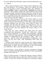
Hue
When asked to identify the color of
an object, you’ll most likely speak
first of its hue. Quite simply, hue is
how we perceive an object’s color
— red, orange, green, blue, etc.
The color wheel in Figure 1 shows
the continuum of color from one
hue to the next. As the wheel illus-
trates, if you were to mix blue and
green paints, you would get blue-
green. Add yellow to green for
yellow-green, and so on.
Chroma
Chroma describes the vividness or
dullness of a color — in other
words, how close the color is to
either gray or the pure hue. For
example, think of the appearance of
a tomato and a radish. The red of
the tomato is vivid, while the radish
appears duller.
Figure 2 shows how chroma
changes as we move from center to
the perimeter. Colors in the center
are gray (dull) and become more
saturated (vivid) as they move
toward the perimeter. Chroma also
is known as saturation.
Attributes
of Color
Yellow
Blue
Green
Red
Figure 1: Hue
Chroma
(Saturation)
Less
More
Chroma
Figure 2: Chromaticity
8
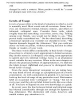
Figure 3: Three-dimensional color system depicting lightness
White
Black
White
Black
Lightness
The luminous intensity of a color — i.e., its degree of lightness — is called
its value. Colors can be classified as light or dark when comparing their
value.
For example, when a tomato and a radish are placed side by side, the red
of the tomato appears to be much lighter. In contrast, the radish has a
darker red value. In Figure 3, the value, or lightness, characteristic is
represented on the vertical axis.
Lightness
Attributes
of Color
continued
The Munsell Scale
In 1905, artist Albert H. Munsell
originated a color ordering system
— or color scale — which is still
used today. The Munsell System of
Color Notation is significant from a
historical perspective because it’s
based on human perception.
Moreover, it was devised before
instrumentation was available for
measuring and specifying color.
The Munsell System assigns
numerical values to the three prop-
erties of color: hue, value and
chroma. Adjacent color samples
represent equal intervals of visual
perception.
The model in Figure 4 depicts the
Munsell Color Tree, which provides
physical samples for judging visual
color. Today’s color systems rely on
instruments that utilize mathematics
to help us judge color.
Three things are necessary to see
color:
• A light source (illuminant)
• An object (sample)
• An observer/processor
We as humans see color because
our eyes process the interaction of
light hitting an object. What if we
replace our eyes with an instrument
—can it see and record the same
color differences that our eyes
detect?
CIE Color Systems
The CIE, or Commission
Internationale de l’Eclairage
(translated as the International
Commission on Illumination), is the
body responsible for international
recommendations for photometry
and colorimetry. In 1931 the CIE
standardized color order systems
by specifying the light source (or
illuminants), the observer and the
methodology used to derive values
for describing color.
The CIE Color Systems utilize
three coordinates to locate a color
in a color space. These color
spaces include:
• CIE XYZ
• CIE L*a*b*
• CIE L*C*h°
To obtain these values, we must
understand how they are calculated.
As stated earlier, our eyes need
three things to see color: a light
source, an object and an
observer/processor. The same
must be true for instruments to see
color. Color measurement instru-
ments receive color the same way
our eyes do — by gathering and
Figure 5: Spectral curve from a measured sample
Figure 4: Munsell Color Tree
Scales for
Measuring
Color
400 500 600 700
Wavelength (nm)
120
100
80
60
40
20
Percent Reflectance
9
400 500 600 700
Figure 6: Daylight (Standard Illuminant D65/10˚)
Wavelength (nm)
120
100
80
60
40
20
Relative Spectral Power
10
Scales for
Measuring Color
continued
filtering the wavelengths of light reflected from an object. The instrument
perceives the reflected light wavelengths as numeric values. These values
are recorded as points across the visible spectrum and are called spectral
data. Spectral data is represented as a spectral curve. This curve is the
color’s fingerprint (Figure 5).
Once we obtain a color’s reflectance curve, we can apply mathematics to
map the color onto a color space.
To do this, we take the reflectance curve and multiply the data by a CIE
standard illuminant. The illuminant is a graphical representation of the light
source under which the samples are viewed. Each light source has a power
distribution that affects how we see color. Examples of different illuminants
are A — incandescent, D65 — daylight (Figure 6) and F2 — fluorescent.
We multiply the result of this calculation by the CIE standard observer.
The CIE commissioned work in 1931 and 1964 to derive the concept of a
standard observer, which is based on the average human response to
wavelengths of light (Figure 7).
In short, the standard observer represents how an average person sees
color across the visible spectrum. Once these values are calculated, we
convert the data into the tristimulus values of XYZ (Figure 8). These
values can now identify a color numerically.
A spectrophotometer measures
spectral data – the amount of
light energy reflected from an
object at several intervals along
the visible spectrum. The
spectral data is shown as
a spectral curve.
2.0
1.5
1.0
0.5
0.0
380 430 480 530 580 630 680 730 780
z(λ)
y(λ)
x(λ)
Wavelength (nm)
Tristimulus Values
2° Observer (CIE 1931)
10° Observer (CIE 1964)
Figure 7: CIE 2° and 10° Standard Observers
300
250
200
150
100
50
0
380 430 480 530 580 630 680 730 780
z(λ)
y(λ)
x(λ)
Wavelength (nm)
Reflectance Intensity
2° Observer (CIE 1931)
10° Observer (CIE 1964)
400 500 600 700
Wavelength (nm)
120
100
80
60
40
20
Reflectance Intensity
400 500 600 700
Wavelength (nm)
120
100
80
60
40
20
Reflectance Intensity
X
X
=
X = 62.04
Y = 69.72
Z = 7.34
Spectral Curve
D65 Illuminant
Standard Observer
Tristimulus Values
Figure 8: Tristimulus values
Percent Reflectance
Relative Spectral Power
Tristimulus Values
2.0
1.5
1.0
0.5
0.0
y
x
Hue
Saturation
11
Figure 9: CIE 1931 (x, y)
chromaticity diagram
Figure 10: Chromaticity diagram
Chromaticity Values
Tristimulus values, unfortunately, have limited use as color specifications
because they correlate poorly with visual attributes. While Y relates to
value (lightness), X and Z do not correlate to hue and chroma.
As a result, when the 1931 CIE standard observer was established, the
commission recommended using the chromaticity coordinates xyz. These
coordinates are used to form the chromaticity diagram in Figure 9. The
notation Yxy specifies colors by identifying value (Y) and the color as
viewed in the chromaticity diagram (x,y).
As Figure 10 shows, hue is represented at all points around the perimeter
of the chromaticity diagram. Chroma, or saturation, is represented by a
movement from the central white (neutral) area out toward the diagram’s
perimeter, where 100% saturation equals pure hue.
12
To overcome the limitations of
chromaticity diagrams like Yxy, the
CIE recommended two alternate,
uniform color scales: CIE 1976
(L*a*b*) or CIELAB, and CIELCH
(L*C*h°).
These color scales are based on
the opponent-colors theory of color
vision, which says that two colors
cannot be both green and red at
the same time, nor blue and yellow
at the same time. As a result,
single values can be used to
describe the red/green and the
yellow/blue attributes.
CIELAB (L*a*b*)
When a color is expressed in
CIELAB, L* defines lightness, a*
denotes the red/green value and
b* the yellow/blue value.
Figures 11 and 12 (on page 13)
show the color-plotting diagrams
for L*a*b*. The a* axis runs from
left to right. A color measurement
movement in the +a direction
depicts a shift toward red. Along
the b* axis, +b movement repre-
sents a shift toward yellow. The
center L* axis shows L = 0 (black
or total absorption) at the bottom.
At the center of this plane is
neutral or gray.
To demonstrate how the L*a*b*
values represent the specific
colors of Flowers A and B, we’ve
plotted their values on the CIELAB
Color Chart in Figure 11.
The a* and b* values for Flowers
A and B intersect at color spaces
identified respectively as points
A and B (see Figure 11). These
points specify each flower’s hue
(color) and chroma (vividness/dull-
ness). When their L* values
(degree of lightness) are added in
Figure 12, the final color of each
flower is obtained.
CIELCH (L*C*h°)
While CIELAB uses Cartesian
coordinates to calculate a color in
a color space, CIELCH uses polar
coordinates. This color expression
can be derived from CIELAB. The
L* defines lightness, C* specifies
chroma and h° denotes hue angle,
an angular measurement.
Expressing
Colors
Numerically
Flower A:
L* = 52.99 a* = 8.82 b* = 54.53
Flower B:
L* = 29.00 a* = 52.48 b* = 22.23
90˚
Yellow
+b*
0˚
Red
+a*
180˚
Green
-a*
Blue
-b*
270˚
Hue
13
Figure 12: The L* value is represented on the center axis. The a* and b* axes
appear on the horizontal plane.
Figure 11: CIELAB color chart
The L*C*h° expression offers an
advantage over CIELAB in that it’s
very easy to relate to the earlier
systems based on physical
samples, like the Munsell Color
Scale.
L* = 116 (Y/Y
n
)
1/3
– 16
a* = 500 [(X/X
n
)
1/3
– (Y/Y
n
)
1/3
]
b* = 200 [(Y/Y
n
)
1/3
– (Z/Z
n
)
1/3
]
L* =116 (Y/Y
n
)
1/3
– 16
C* = (a
2
+ b
2
)
1/2
h° = arctan (b*/a*)
X
n
, Y
n
, Z
n
, are values for a
reference white for the
illumination/observer used.
14
Color
Differences,
Notation and
Tolerancing
Delta CIELAB and CIELCH
Assessment of color is more than a
numeric expression. Usually it’s an
assessment of the color difference
(delta) from a known standard.
CIELAB and CIELCH are used to
compare the colors of two objects.
The expressions for these color
differences are ∆L* ∆a* ∆b* or DL*
Da* Db*, and ∆L* ∆C* ∆H* or DL*
DC* DH* (∆ or D symbolizes
“delta,” which indicates difference).
Given ∆L* ∆a* ∆b*, the total differ-
ence or distance on the CIELAB
diagram can be stated as a single
value, known as ∆E*.
∆E*
ab
= [(∆L
2
) + (∆a
2
) + (∆b
2
)]
1/2
Let’s compare the color of Flower
A to Flower C, pictured below.
Separately, each would be classi-
fied as a yellow rose. But what is
their relationship when set side by
side? How do the colors differ?
Using the equation for ∆L* ∆a*
∆b*, the color difference between
Flower A and Flower C can be
expressed as:
∆L* = +11.10
∆a* = –6.10
∆b* = –5.25
The total color difference can be
expressed as ∆E*=13.71
The values for Flowers A and C
are shown at the bottom of this
page. On the a* axis, a reading of
–6.10 indicates greener or less red.
On the b* axis, a reading of –5.25
indicates bluer or less yellow. On the
L* plane, the measurement differ-
ence of +11.10 shows that Flower
C is lighter than Flower A.
If the same two flowers were
compared using CIELCH, the color
differences would be expressed as:
∆L* = +11.10
∆C* = –5.88
∆H* = 5.49
Referring again to the flowers
shown below, the ∆C* value of
–5.88 indicates that Flower C is less
chromatic, or less saturated. The
∆H* value of 5.49 indicates that
Flower C is greener in hue than
Flower A. The L* and ∆L* values are
identical for CIELCH and CIELAB.
Flower A: L* = 52.99 a* = 8.82 b* = 54.53
Flower C: L*=64.09 a*=2.72 b*=49.28
Color difference of Flower C to A
∆L* = +11.10, ∆a* = –6.10, ∆b* = –5.25
∆E*
ab
= [(+ 11.1)
2
+ (–6.1)
2
+ (–5.25)
2
]
1/2
∆E*
ab
= 13.71
15
Hue
Chroma
Lightness
Figure 13: Tolerance ellipsoid
Standard
a*
b*
Lightness (L*)
Figure 14: CIELAB tolerance box
a*
b*
∆a*
∆b*
Samples within
the ellipsoid
are visually
acceptable
Samples within the box
and not in the ellipsoid are
numerically correct but
visually unacceptable
Figure 15: Numerically correct
vs. visually acceptable
CIE Color Space Notation
∆L* = difference in lightness/darkness value
+
= lighter
–
= darker
∆a* = difference on red/green axis
+
= redder
–
= greener
∆b* = difference on yellow/blue axis
+
= yellower
–
= bluer
∆C* = difference in chroma
+
= brighter
–
= duller
∆H* = difference in hue
∆E* = total color difference value
Refer to Figure 11 on page 10.
Visual Color and Tolerancing
Poor color memory, eye fatigue, color blindness and viewing
conditions can all affect the human eye’s ability to distinguish
color differences. In addition to those limitations, the eye does
not detect differences in hue (red, yellow, green, blue, etc.),
chroma (saturation) or lightness equally. In fact, the average
observer will see hue differences first, chroma differences
second and lightness differences last. Visual acceptability is
best represented by an ellipsoid (Figure 13).
As a result, our tolerance for an acceptable color match
consists of a three-dimensional boundary with varying limits
for lightness, hue and chroma, and must agree with visual
assessment. CIELAB and CIELCH can be used to create
those boundaries. Additional tolerancing formulas, known
as CMC and CIE94, produce ellipsoidal tolerances.
CIELAB Tolerancing
When tolerancing with CIELAB, you must choose a difference
limit for ∆L* (lightness), ∆a* (red/green), and ∆b* (yellow/blue).
These limits create a rectangular tolerance box around the
standard (Figure 14).
When comparing this tolerance box with the visually accepted
ellipsoid, some problems emerge. A box-shaped tolerance
around the ellipsoid can give good numbers for unacceptable
color. If the tolerance box is made small enough to fit within
the ellipsoid, it is possible to get bad numbers for visually
acceptable color (Figure 15).
16
Color Differences,
Notation and
Tolerancing
continued
CIELCH Tolerancing
CIELCH users must choose a difference limit for ∆L* (lightness), ∆C*
(chroma) and ∆H* (hue). This creates a wedge-shaped box around the
standard. Since CIELCH is a polar-coordinate system, the tolerance box
can be rotated in orientation to the hue angle (Figure 16).
When this tolerance is compared with the ellipsoid, we can see that it
more closely matches human perception. This reduces the amount of
disagreement between the observer and the instrumental values
(Figure 17).
CMC Tolerancing
CMC is not a color space but rather a tolerancing system. CMC toler-
ancing is based on CIELCH and provides better agreement between
visual assessment and measured color difference. CMC tolerancing was
developed by the Colour Measurement Committee of the Society of Dyers
and Colourists in Great Britain and became public domain in 1988.
The CMC calculation mathematically defines an ellipsoid around the stan-
dard color with semi-axis corresponding to hue, chroma and lightness. The
ellipsoid represents the volume of acceptable color and automatically
varies in size and shape depending on the position of the color in color
space.
Figure 18 (on page 17) shows the variation of the ellipsoids throughout
color space. The ellipsoids in the orange area of color space are longer
and narrower than the broader and rounder ones in the green area. The
size and shape of the ellipsoids also change as the color varies in chroma
and/or lightness.
The CMC equation allows you to vary the overall size of the ellipsoid to
better match what is visually acceptable. By varying the commercial factor
(cf), the ellipsoid can be made as large or small as necessary to match
visual assessment. The cf value is the tolerance, which means that if
cf=1.0, then ∆E CMC less than 1.0 would pass, but more than 1.0 would
fail (see Figure 19 on page 17).
Since the eye will generally accept larger differences in lightness (l) than in
chroma (c), a default ratio for (l:c) is 2:1. A 2:1 ratio will allow twice as
much difference in lightness as in chroma. The CMC equation allows this
ratio to be adjusted to achieve better agreement with visual assessment
(see Figure 20 on page 18).
∆H*
∆L*
∆C*
Standard
Lightness
Chroma
Figure 16: CIELCH tolerance
wedge
a*
b*
∆C*
∆C*
∆C*
∆H*
∆H*
∆H*
Figure 17: CIELCH tolerance
ellipsoids
Cross sections
of the ellipsoid
Standard
cf = 1
cf = 0.5
Chroma
Chroma
Hue
Hue
Hue and chromaticity tolerances
become smaller as lightness
increases or decreases
Figure 19: Commercial factor (cf) of tolerances
Figure 18: Tolerance ellipsoids in color space
Yellow
Blue
Red
Green
Tolerance ellipsoids are
tightly packed in the
orange region.
Tolerance ellipsoids
are larger in the
green region.
17
18
CIE94 Tolerancing
In 1994 the CIE released a new tolerance method called CIE94. Like
CMC, the CIE94 tolerancing method also produces an ellipsoid. The user
has control of the lightness (kL) to chroma (Kc) ratio, as well as the
commercial factor (cf). These settings affect the size and shape of the
ellipsoid in a manner similar to how the l:c and cf settings affect CMC.
However, while CMC is targeted for use in the textile industry, CIE94 is
targeted for use in the paint and coatings industry.You should consider the
type of surface being measured when choosing between these two toler-
ances. If the surface is textured or irregular, CMC may be the best fit. If the
surface is smooth and regular, CIE94 may be the best choice.
Visual Assessment vs. Instrumental
Though no color tolerancing system is perfect, the CMC and CIE94 equa-
tions best represent color differences as our eyes see them.
Choosing the Right Tolerance
When deciding which color difference calculation to use, consider the
following five rules (Billmeyer 1970 and 1979):
1. Select a single method of calculation and use it consistently.
2. Always specify exactly how the calculations are made.
3. Never attempt to convert between color differences calculated by
different equations through the use of average factors.
4. Use calculated color differences only as a first approximation in setting
tolerances, until they can be confirmed by visual judgments.
5. Always remember that nobody accepts or rejects color because of
numbers — it is the way it looks that counts.
% Agreement
Tolerance Method with Visual
CIELAB 75%
CIELCH 85%
CMC or CIE94 95%
Figure 20: CMC tolerance
ellipsoids
Hue
Chroma
Lightness
(1.4:1)
(2:1)
Color Differences,
Notation and
Tolerancing
continued
19
Other
Color
Expressions
White and Yellow Indices
Certain industries, such as paint,
textiles and paper manufacturing,
evaluate their materials and prod-
ucts based on standards of white-
ness. Typically, this whiteness
index is a preference rating for how
white a material should appear, be
it photographic and printing paper
or plastics.
In some instances, a manufacturer
may want to judge the yellowness
or tint of a material. This is done to
determine how much that object’s
color departs from a preferred
white toward a bluish tint.
The effect of whiteness or yellow-
ness can be significant, for
example, when printing inks or
dyes on paper. A blue ink printed
on a highly-rated white stock will
look different than the same ink
printed on newsprint or another
low-rated stock.
The American Standards Test
Methods (ASTM) has defined
whiteness and yellowness indices.
The E313 whiteness index is used
for measuring near-white, opaque
materials such as paper, paint and
plastic. In fact, this index can be
used for any material whose color
appears white.
The ASTM’s E313 yellowness
index is used to determine the
degree to which a sample’s color
shifts away from an ideal white.
The D1925 yellowness index is
used for measuring plastics.
The same blue ink looks like a different color when
printed on paper of various whiteness
20
Glossary
absolute white – In theory, a mate-
rial that perfectly reflects all light
energy at every visible wavelength.
In practice, a solid white with known
spectral reflectance data that is used
as the “reference white” for all meas-
urements of absolute reflectance.
When calibrating a spectropho-
tometer, often a white ceramic
plaque is measured and used as the
absolute white reference.
absorb/absorption – Dissipation of
the energy of electromagnetic waves
into other forms (e.g., heat) as a
result of its interaction with matter; a
decrease in directional transmittance
of incident radiation, resulting in a
modification or conversion of the
absorbed energy.
achromatic color – A neutral color
that has no hue (white, gray or black).
additive primaries – Red, green
and blue light. When all three addi-
tive primaries are combined at 100%
intensity, white light is produced.
When these three are combined at
varying intensities, a gamut of
different colors is produced.
Combining two primaries at 100%
produces a subtractive primary,
either cyan, magenta or yellow:
100% red + 100% green = yellow
100% red + 100% blue = magenta
100% green + 100% blue = cyan
See
subtractive primaries
appearance – An object’s or mate-
rial’s manifestation through visual
attributes such as size, shape, color,
texture, glossiness, transparency,
opacity, etc.
artificial daylight – Term loosely
applied to light sources, frequently
equipped with filters, that try to
reproduce the color and spectral
distribution of daylight. A more
specific definition of the light source
is preferred.
attribute – Distinguishing character-
istic of a sensation, perception or
mode of appearance. Colors are
often described by their attributes of
hue, chroma (or saturation) and
lightness.
black – In theory, the complete
absorption of incident light; the
absence of any reflection. In prac-
tice, any color that is close to this
ideal in a relative viewing situation —
i.e., a color of very low saturation
and very low luminance.
brightness – The dimension of color
that refers to an achromatic scale,
ranging from black to white. Also
called lightness, luminous
reflectance or transmittance (q.v.).
Because of confusion with satura-
tion, the use of this term should be
discouraged.
c* – Abbreviation for chromaticity.
chroma/chromaticity – The inten-
sity or saturation level of a particular
hue, defined as the distance of
departure of a chromatic color from
the neutral (gray) color with the
same value. In an additive color-
mixing environment, imagine mixing
a neutral gray and a vivid red with
the same value. Starting with the
neutral gray, add small amounts of
red until the vivid red color is
achieved. The resulting scale
obtained would represent increasing
chroma. The scale begins at zero for
neutral colors, but has no arbitrary
end. Munsell originally established
10 as the highest chroma for a
vermilion pigment and related other
pigments to it. Other pigments with
higher chroma were noted, but the
original scale remained. The chroma
scale for normal reflecting materials
may extend as high as 20, and for
fluorescent materials it may be as
high as 30.
chromatic – Perceived as having a
hue — not white, gray or black.
chromaticity coordinates (CIE) –
The ratios of each of the three tris-
timulus values X, Y and Z in relation
to the sum of the three — desig-
nated as x, y and z respectively.
They are sometimes referred to as
the trichromatic coefficients. When
written without subscripts, they are
assumed to have been calculated for
illuminant C and the 2° (1931) stan-
dard observer unless specified
otherwise. If they have been
21
obtained for other illuminants or
observers, a subscript describing the
observer or illuminant should be
used. For example, x10 and y10 are
chromaticity coordinates for the 10°
observer and illuminant C.
chromaticity diagram (CIE) – A
two-dimensional graph of the chro-
maticity coordinates (x as the
abscissa and y as the ordinate),
which shows the spectrum locus
(chromaticity coordinates of mono-
chromatic light, 380-770nm). It has
many useful properties for
comparing colors of both luminous
and non-luminous materials.
CIE (Commission Internationale de
l’Eclairage) – The International
Commission on Illumination, the
primary international organization
concerned with color and color
measurement.
CIE 1976 L*a*b* color space – A
uniform color space utilizing an
Adams-Nickerson cube root formula,
adopted by the CIE in 1976 for use
in the measurement of small color
differences.
CIE 1976 L*u*v* color space – A
uniform color space adopted in 1976.
Appropriate for use in additive mixing
of light (e.g., color TV).
CIE chromaticity coordinates –
See
chromaticity coordinates (CIE).
CIE chromaticity diagram – See
chromaticity diagram (CIE).
CIE daylight illuminants – See
daylight illuminants (CIE).
CIE luminosity function (y) – See
luminosity function (CIE).
CIE standard illuminants – See
standard illuminants (CIE).
CIE standard observer – See
stan-
dard observer (CIE).
CIE tristimulus values – See
tris-
timulus values (CIE).
CIELAB (or CIE L*a*b*, CIE Lab) –
Color space in which values L*, a*
and b* are plotted using Cartesian
coordinate system. Equal distances
in the space approximately represent
equal color differences. Value L*
represents lightness; value a* repre-
sents the red/green axis; and value
b* represents the yellow/blue axis.
CIELAB is a popular color space for
use in measuring reflective and
transmissive objects.
CMC (Colour Measurement
Committee of the Society of Dyes
and Colourists of Great Britain) –
Organization that developed and
published in 1988 a more logical,
ellipse-based equation based on
L*C*h˚ color space for computing DE
(see
delta E*
) values as an alterna-
tive to the rectangular coordinates of
the CIELAB color space.
color – One aspect of appearance; a
stimulus based on visual response to
light, consisting of the three dimen-
sions of hue, saturation and light-
ness.
color attribute – A three-dimen-
sional characteristic of the appear-
ance of an object. One dimension
usually defines the lightness, the
other two together define the chro-
maticity.
color difference – The magnitude
and character of the difference
between two colors under specified
conditions.
color-matching functions –
Relative amounts of three additive
primaries required to match each
wavelength of light. The term is
generally used to refer to the CIE
standard observer color-matching
functions.
color measurement – Physical
measurement of light radiated, trans-
mitted or reflected by a specimen
under specified condition and mathe-
matically transformed into standard-
ized colorimetric terms. These terms
can be correlated with visual evalua-
tions of colors relative to one
another.
color model – A color-measurement
scale or system that numerically
specifies the perceived attributes of
color. Used in computer graphics
applications and by color measure-
ment instruments.
color order systems – Systems
used to describe an orderly three-
dimensional arrangement of colors.
Three bases can be used for
ordering colors: 1) an appearance
basis (i.e., a psychological basis) in
terms of hue, saturation and light-
ness; an example is the Munsell
System; 2) an orderly additive color
mixture basis (i.e., a psychophysical
basis); examples are the CIE System
and the Ostwald System; and 3) an
orderly subtractive color mixture
basis; an example is the Plochere
Color System based on an orderly
mixture of inks.
color space – Three-dimensional
solid enclosing all possible colors.
The dimensions may be described in
various geometries, giving rise to
various spacings within the solid.
color specification – Tristimulus
values, chromaticity coordinates and
luminance value, or other color-scale
values, used to designate a color
numerically in a specified color
system.
color temperature – A measure-
ment of the color of light radiated by
a black body while it is being heated.
This measurement is expressed in
terms of absolute scale, or degrees
Kelvin. Lower Kelvin temperatures
such as 2400K are red; higher
temperatures such as 9300K are
blue. Neutral temperature is white, at
6504K.
color wheel – The visible spectrum’s
continuum of colors arranged in a
circle, where complementary colors
such as red and green are located
directly across from each other.
colorants – Materials used to create
colors — dyes, pigments, toners,
waxes, phosphors.
colorimeter – An optical measure-
ment instrument that responds to
color in a manner similar to the
human eye — by filtering reflected
light into its dominant regions of red,
green and blue.
22
colorimetric – Of, or relating to,
values giving the amounts of three
colored lights or receptors — red,
green and blue.
colorist – A person skilled in the art
of color matching (colorant formula-
tion) and knowledgeable concerning
the behavior of colorants in a partic-
ular material; a tinter (q.v.) (in the
American usage) or a shader. The
word “colorist” is of European origin.
complements – Two colors that
create neutral gray when combined.
On a color wheel, complements are
directly opposite from each other:
blue/yellow, red/green and so on.
contrast – The level of variation
between light and dark areas in an
image.
D65 – The CIE standard illuminant
that represents a color temperature
of 6504K. This is the color tempera-
ture most widely used in graphic
arts industry viewing booths. See
Kelvin (K)
.
daylight illuminants (CIE) – Series
of illuminant spectral power distribu-
tion curves based on measurements
of natural daylight and recommended
by the CIE in 1965. Values are
defined for the wavelength region
300 to 830nm. They are described in
terms of the correlated color temper-
ature. The most important is D65
because of the closeness of its
correlated color temperature to that
of illuminant C, 6774K. D75 bluer
than D65 and D55 yellower than D65
are also used.
delta (D or ∆) – A symbol used to
indicate deviation or difference.
delta E*, delta e* – The total color
difference computed with a color
difference equation (∆E
ab
or ∆E
cmc
).
In color tolerancing, the symbol DE
is often used to express Delta Error.
dye – A soluble colorant — as
opposed to pigment, which is insol-
uble.
dynamic range – An instrument’s
range of measurable values, from
the lowest amount it can detect to
the highest amount it can handle.
electromagnetic spectrum – The
massive band of electromagnetic
waves that pass through the air in
different sizes, as measured by
wavelength. Different wavelengths
have different properties, but most
are invisible — and some completely
undetectable — to human beings.
Only wavelengths that are between
380 and 720 nanometers are visible,
producing light. Waves outside the
visible spectrum include gamma
rays, x-rays, microwaves and radio
waves.
emissive object – An object that
emits light. Emission is usually
caused by a chemical reaction, such
as the burning gasses of the sun or
the heated filament of a light bulb.
fluorescent lamp – A glass tube
filled with mercury gas and coated
on its inner surface with phosphors.
When the gas is charged with an
electrical current, radiation is
produced. This, in turn, energizes the
phosphors, causing them to glow.
gloss – An additional parameter to
consider when determining a color
standard, along with hue, value,
chroma, the texture of a material and
whether the material has metallic or
pearlescent qualities. Gloss is an
additional tolerance that may be
specified in the Munsell Color
Tolerance Set. The general rule for
evaluating the gloss of a color
sample is the higher the gloss unit,
the darker the color sample will
appear. Conversely, the lower the
gloss unit, the lighter a sample will
appear.
Gloss is measured in gloss units,
which use the angle of measurement
and the gloss value (e.g. 60˚ gloss =
29.8). A 60˚ geometry is recom-
mended by the American Society for
Testing and Materials (ASTM) D523
standard for the general evaluation
of gloss.
grayscale – An achromatic scale
ranging from black through a series
of successively lighter grays to white.
Such a series may be made up of
steps that appear to be equally
distant from one another (such as
the Munsell Value Scale), or it may
be arranged according to some other
criteria such as a geometric progres-
sion based on lightness. Such scales
may be used to describe the relative
amount of difference between two
similar colors.
hue – 1) The first element in the
color-order system, defined as the
attribute by which we distinguish red
from green, blue from yellow, etc.
Munsell defined five principal hues
(red, yellow, green, blue and purple)
and five intermediate hues (yellow-
red, green-yellow, blue-green,
purple-blue and red-purple. These 10
hues (represented by their corre-
sponding initials R, YR, Y, GY, G,
BG, B, PB, P and RP) are equally
spaced around a circle divided into
100 equal visual steps, with the zero
point located at the beginning of the
red sector. Adjacent colors in this
circle may be mixed to obtain contin-
uous variation from one hue to
another. Colors defined around the
hue circle are known as chromatic
colors. 2) The attribute of color by
means of which a color is perceived
to be red, yellow, green, blue, purple,
etc. White, black and gray possess
no hue.
illuminant – Mathematical descrip-
tion of the relative spectral power
distribution of a real or imaginary
light source — i.e., the relative
energy emitted by a source at each
wavelength in its emission spectrum.
Often used synonymously with “light
source” or “lamp,” though such usage
is not recommended.
illuminant A (CIE) – Incandescent
illumination, yellow-orange in color,
with a correlated color temperature
of 2856K. It is defined in the wave-
length range of 380 to 770nm.
illuminant C (CIE) – Tungsten illumi-
nation that simulates average
daylight, bluish in color, with a corre-
lated color temperature of 6774K.
illuminants D (CIE) – Daylight illu-
minants, defined from 300 to 830nm
(the UV portion 300 to 380nm being
necessary to correctly describe
colors that contain fluorescent dyes
or pigments). They are designated as
D, with a subscript to describe the
Glossary
continued
23
correlated color temperature; D65 is
the most commonly used, having a
correlated color temperature of
6504K, close to that of illuminant C.
They are based on actual measure-
ments of the spectral distribution of
daylight.
integrating sphere – A sphere
manufactured or coated with a highly
reflective material that diffuses light
within it.
Kelvin (K) – Unit of measurement
for color temperature. The Kelvin
scale starts from absolute zero,
which is -273˚ Celsius.
light – 1) Electromagnetic radiation
of which a human observer is aware
through the visual sensations that
arise from the stimulation of the
retina of the eye. This portion of the
spectrum includes wavelengths from
about 380 to 770nm. Thus, to speak
of ultraviolet light is incorrect
because the human observer cannot
see radiant energy in the ultraviolet
region. 2) Adjective meaning high
reflectance, transmittance or level of
illumination as contrasted to dark, or
low level of intensity.
light source – An object that emits
light or radiant energy to which the
human eye is sensitive. The emission
of a light source can be described by
the relative amount of energy
emitted at each wavelength in the
visible spectrum, thus defining the
source as an illuminant. The emis-
sion also may be described in terms
of its correlated color temperature.
lightness – Perception by which
white objects are distinguished from
gray, and light-colored objects from
dark-colored.
luminosity function (y) (CIE) – A
plot of the relative magnitude of the
visual response as a function of
wavelength from about 380 to
780nm, adopted by CIE in 1924.
metamerism – A phenomenon
exhibited by a pair of colors that
match under one or more sets of illu-
minants (be they real or calculated),
but not under all illuminants.
Munsell Color System – The color
identification of a specimen by its
Munsell hue, value and chroma as
visually estimated by comparison
with the Munsell Book of Color.
nanometer (nm) – Unit of length
equal to 10-9 meter (a.k.a. one
billionth of a meter, or a milli-micron).
observer – The human viewer who
receives a stimulus and experiences
a sensation from it. In vision, the
stimulus is a visual one and the
sensation is an appearance.
observer, standard – See
standard
observer.
radiant energy – A form of energy
consisting of the electromagnetic
spectrum, which travels at 299,792
kilometers/second (186,206
miles/second) through a vacuum,
and more slowly in denser media
(air, water, glass, etc.). The nature of
radiant energy is described by its
wavelength or frequency, although it
also behaves as distinct quanta
(“corpuscular theory”). The various
types of energy may be transformed
into other forms of energy (electrical,
chemical, mechanical, atomic,
thermal, radiant), but the energy
itself cannot be destroyed.
reflectance – The ratio of the inten-
sity of reflected radiant flux to that of
incident flux. In popular usage, it is
considered the ratio of the intensity
of reflected radiant energy to that
reflected from a defined reference
standard.
reflectance, specular – See
spec-
ular reflectance.
reflectance, total – See
total
reflectance.
saturation – The attribute of color
perception that expresses the
amount of departure from a gray of
the same lightness. All grays have
zero saturation (ASTM). See
chroma/chromaticity.
scattering – Diffusion or redirection of
radiant energy encountering particles
of different refractive index. Scattering
occurs at any such interface, at the
surface, or inside a medium containing
particles.
spectral power distribution curve
– Intensity of radiant energy as a
function of wavelength, generally
given in relative power terms.
spectrophotometer – Photometric
device that measures spectral trans-
mittance, spectral reflectance or rela-
tive spectral emittance.
spectrophotometric curve – A
curve measured on a spectropho-
tometer; a graph with relative
reflectance or transmittance (or
absorption) as the ordinate, plotted
with wavelength or frequency as the
abscissa.
spectrum – Spatial arrangement of
components of radiant energy in
order of their wavelengths, wave
number or frequency.
specular gloss – Relative luminous
fractional reflectance from a surface
in the mirror or specular direction. It
is sometimes measured at 60˚ rela-
tive to a perfect mirror.
specular reflectance – Reflectance
of a beam of radiant energy at an
angle equal but opposite to the inci-
dent angle; the mirror-like reflectance.
The magnitude of the specular
reflectance on glossy materials
depends on the angle and the differ-
ence in refractive indices between
two media at a surface. The magni-
tude may be calculated from
Fresnel’s Law.
specular reflectance excluded
(SCE) – Measurement of reflectance
made in such a way that the spec-
ular reflectance is excluded from the
measurement; diffuse reflectance.
The exclusion may be accomplished
by using 0˚ (perpendicular) incidence
on the samples. This then reflects
the specular component of the
reflectance back into the instrument
by use of black absorbers or light
traps at the specular angle when the
incident angle is not perpendicular,
or in directional measurements by
measuring at an angle different from
the specular angle.
24
specular reflectance included
(SCI) – Measurement of the total
reflectance from a surface, including
the diffuse and specular reflectances.
standard – A reference against
which instrumental measurements
are made.
standard illuminants (CIE) –
Known spectral data established by
the CIE for four different types of
light sources. When using tristimulus
data to describe a color, the illumi-
nant must also be defined. These
standard illuminants are used in
place of actual measurements of the
light source.
standard observer (CIE) – 1) A
hypothetical observer having the tris-
timulus color-mixture data recom-
mended in 1931 by the CIE for a 2˚
viewing angle. A supplementary
observer for a larger angle of 10˚
was adopted in 1964. 2) The spectral
response characteristics of the
average observer defined by the
CIE. Two such sets of data are
defined, the 1931 data for the 2˚
visual field (distance viewing) and
the 1964 data for the annular 10˚
visual field (approximately arm’s
length viewing). By custom, the
assumption is made that if the
observer is not specified, the tristim-
ulus data has been calculated for the
1931, or 2˚ field observer. The use of
the 1964 data should be specified.
subtractive primaries – Cyan,
magenta and yellow. Theoretically,
when all three subtractive primaries
are combined at 100% on white
paper, black is produced. When
these are combined at varying inten-
sities, a gamut of different colors is
produced. Combining two primaries
at 100% produces an additive
primary, either red, green or blue:
100% cyan + 100% magenta = blue
100% cyan + 100% yellow = green
100% magenta + 100% yellow = red
tint – 1)
verb:
To mix white pigment
with absorbing (generally chromatic)
colorants. 2)
noun:
The color
produced by mixing white pigment
with absorbing (generally chromatic)
colorants. The resulting mixture is
lighter and less saturated than the
color without the white added.
total reflectance – Reflectance of
radiant flux reflected at all angles
from the surface, thus including both
diffuse and specular reflectances.
transparent – Describes a material
that transmits light without diffusion
or scattering.
tristimulus – Of, or consisting of,
three stimuli; generally used to
describe components of additive
mixture required to evoke a partic-
ular color sensation.
tristimulus colorimeter – An instru-
ment that measures tristimulus
values and converts them to chro-
maticity components of color.
tristimulus values (CIE) –
Percentages of the components in a
three-color additive mixture necessary
to match a color; in the CIE system,
they are designated as X, Y and Z.
The illuminant and standard observer
color-matching functions used must
be designated; if they are not, the
assumption is made that the values
are for the 1931 observer (2˚ field)
and illuminant C. The values obtained
depend on the method of integration
used, the relationship of the nature of
the sample and the instrument design
used to measure the reflectance or
transmittance. Tristimulus values are
not, therefore, absolute values char-
acteristic of a sample, but relative
values dependent on the method
used to obtain them. Approximations
of CIE tristimulus values may be
obtained from measurements made
on a tristimulus colorimeter that gives
measurements generally normalized
to 100. These must then be normal-
ized to equivalent CIE values. The
filter measurements should be prop-
erly designated as R, G and B
instead of X, Y and Z.
value – Indicates the degree of light-
ness or darkness of a color in rela-
tion to a neutral gray scale. The
scale of value (or V, in the Munsell
system of color notation) ranges
from 0 for pure black to 10 for pure
white. The value scale is neutral or
without hue.
X – 1) One of the three CIE tristim-
ulus values; the red primary. 2)
Spectral color-matching functions of
the CIE standard observer used for
calculating the X tristimulus value. 3)
One of the CIE chromaticity coordi-
nates calculated as the fraction of
the sum of the three tristimulus
values attributable to the X value.
Y – 1) One of the three CIE tristim-
ulus values, equal to the luminous
reflectance or transmittance; the
green primary. 2) Spectral color-
matching function of the CIE stan-
dard observer used for calculating Y
tristimulus value. 3) One of the CIE
chromaticity coordinates calculated
as the fraction of the sum of the
three tristimulus values, attributable
to the Y value.
Z – 1) One of the three CIE tristim-
ulus values; the blue primary. 2)
Spectral color-matching function of
the CIE standard observer used for
calculating the Z tristimulus value. 3)
One of the CIE chromaticity coordi-
nates calculated as the fraction of
the sum of the three tristimulus
values attributable to the Z primary.
Glossary
continued