Tài liệu Hyper-Threading Technology Architecture and Microarchitecture ppt
Bạn đang xem bản rút gọn của tài liệu. Xem và tải ngay bản đầy đủ của tài liệu tại đây (428.2 KB, 14 trang )
Hyper-Threading Technology Architecture and Microarchitecture 1
Hyper-Threading Technology Architecture a
nd
M
i
cro
a
rch
itectu
r
e
Deborah T. Marr, Desktop Products Group,
I
ntel Corp.
Frank Binns, Desktop ProductsGroup,
I
ntel Corp.
David L. Hill, Desktop Products Group,
I
ntel Corp.
Glenn Hinton, Desktop Products Group,
I
ntel Corp.
David A. Koufaty, Desktop Products Group,
I
ntel Corp.
J. Alan Miller, Desktop Products Group,
I
ntel Corp.
Michael Upton, CPU Architecture, Desktop Products Group,
I
ntel Corp.
I
ndex words: architecture, microarchitecture, Hyper-Threading Technology, simultaneous multi-
threading, multiprocessor
ABSTRACT
I
n
tel
’s Hyper-Threading Technology brings the concept
of simultaneous multi-threading to the
I
nt
el
Architecture. Hyper-Threading Technology makes a
single physical processor appear as two logical
processors; the physical execution resources are shared
and the architecture state is duplicated for the two
logical processors.
From a software or architecture
perspective, this means operating systems and user
programs can schedule processes or threads to logical
processors as they would on multiple physical
processors. From a microarchitecture perspective, this
means that instructions from both logical processors
will persist and execute simultaneously on shared
execution resources.
This paper describes the Hyper-Threading Technology
architecture, and discusses the microarchitecture details
of
I
nt
el
's first implementation on the
I
n
tel
Xeon
processor family. Hyper-Threading Technology is an
important addition to
I
nt
el
’s enterprise product line and
will be integrated into a wide variety of products.
I
n
tel
is a registered trademark of
I
nt
el
Corporation or
its subsidiaries in the United States and other countries.
Xeon is a trademark of
I
n
tel
Corporation or its
subsidiaries in the United States and other countries.
INTRODUCTION
The amazing
growth of the
I
nternet and
telecommunications is powered by ever-faster systems
demanding increasingly higher levels of processor
performance. To keep up with this demand we cannot
rely entirely on traditional approaches to processor
design. Microarchitecture techniques used to achieve
past processor performance
improvement–super- pipelining, branch prediction,
super-scalar execution, out-of-order execution,
caches–have
made microprocessors
increasingly more complex, have more transistors, and
consume more power.
I
n fact, transistor counts and
power are increasing at rates greater than processor
performance. Processor architects are therefore
looking for ways to improve performance at a greater
rate than transistor counts and
power dissipation.
I
nt
el
’s Hyper-Threading
Technology is one solution.
Processor Microarchitecture
Traditional approaches to processor design have
focused on higher clock speeds, instruction-level
parallelism
(ILP),
and caches. Techniques to achieve
higher clock speeds involve pipelining the
microarchitecture to finer granularities, also called
super-pipelining. Higher clock frequencies can greatly
improve performance by increasing the number of
instructions that can be executed each second. Because
there will be far more instructions in-flight in a super-
pipelined microarchitecture, handling of events that
disrupt the pipeline, e.g., cache misses, interrupts and
branch mispredictions, can be costly.
Intel Technology Journal Q1, 2002
I
LP refers to techniques to increase the number of
instructions executed each clock cycle. For example, a
super-scalar processor has multiple parallel execution
units that can process instructions simultaneously. With
super-scalar execution, several instructions can be
executed each clock cycle. However, with simple in-
order execution, it is not enough to simply have multiple
execution units. The challenge is to find enough
instructions to execute. One technique is out-of-order
execution where a large window of instructions is
simultaneously evaluated and sent to execution units,
based on instruction dependencies rather than program
25
Power
20
Die Size
SPECInt Perf
15
10
5
0
i486 Pentium(TM)
Processor
Pentium(TM) 3
Processor
Pentium(TM)
4
Processor
order.
Accesses to DRAM memory are slow compared to
execution speeds of the processor. One technique to
reduce this latency is to add fast caches close to the
processor. Caches can provide fast memory access to
frequently accessed data or instructions. However,
caches can only be fast when they are small. For this
reason, processors often are designed with a cache
hierarchy in which fast, small caches are located and
operated at access latencies very close to that of the
processor core, and progressively larger caches, which
handle less frequently accessed data or instructions, are
implemented with longer access latencies. However,
there will always be times when the data needed will not
be in any processor cache. Handling such cache misses
requires accessing memory, and the processor is likely
to quickly run out of instructions to execute before
stalling on the cache miss.
The vast majority of techniques to improve processor
performance from one generation to the next is complex
and often adds significant die-size and power costs.
These techniques increase performance but not with
100% efficiency; i.e., doubling the number of execution
units in a processor does not double the performance of
the processor, due to limited parallelism in instruction
flows. Similarly, simply doubling the clock rate does
not double the performance due to the number of
processor cycles lost to branch mispredictions.
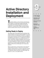
Figure 1: Single-stream performance vs. cost
Figure 1 shows the relative increase in performance and
the costs, such as die size and power, over the last ten
years on
I
n
tel
processors
1
.
I
n order to isolate the
microarchitecture impact, this comparison assumes that
the four generations of processors are on the same
silicon process technology and that the speed-ups are
normalized to the performance of an
I
n
tel
486
processor. Although we use
I
nt
el
’s processor history in
this example, other high-performance processor
manufacturers during this time period would have
similar trends.
I
n
tel
’s processor performance, due to
microarchitecture advances alone, has improved integer
performance five- or six-fold
1
. Most integer
applications have limited
I
LP and the instruction flow
can be hard to predict.
Over the same period, the relative die size has gone up
fifteen-fold, a three-times-higher rate than the gains in
integer performance. Fortunately, advances in silicon
process technology allow more transistors to be packed
into a given amount of die area so that the actual
measured die size of each generation microarchitecture
has not increased significantly.
The relative power increased almost eighteen-fold
during this period
1
. Fortunately, there exist a number of
known techniques to significantly reduce power
consumption on processors and there is much on-going
research in this area. However, current processor power
dissipation is at the limit of what can be easily dealt
with in desktop platforms and we must put greater
emphasis on improving performance in conjunction with
new technology, specifically to control power.
1
These data are approximate and are intended only to show
trends, not actual performance.
I
nt
el
486 is a trademark of
I
n
tel
Corporation or its
subsidiaries in the United States and other countries.
Thread-Level Parallelism
A look at today’s software trends reveals that server
applications consist of multiple threads or processes that
can be executed in parallel. On-line transaction
processing and Web services have an abundance of
software threads that can be executed simultaneously
for faster performance. Even desktop applications are
becoming increasingly parallel.
I
nt
el
architects have
been trying to leverage this so-called thread-level
parallelism (TLP) to gain a better performance vs.
transistor count and power ratio.
I
n both the high-end and mid-range server markets,
multiprocessors have been commonly used to get more
performance from the system. By adding more
processors, applications potentially get substantial
event multi-threading techniques do not achieve optimal
overlap of many sources of inefficient resource usage,
such as branch mispredictions, instruction
dependencies, etc.
Finally, there is simultaneous multi-threading, where
multiple threads can execute on a single processor
without switching. The threads execute simultaneously
and make much better use of the resources. This
approach makes the most effective use of processor
resources: it maximizes the performance vs. transistor
count and power consumption.
Hyper-Threading Technology brings the simultaneous
multi-threading approach to the
Intel
architecture.
I
n
this paper we discuss the architecture and the first
implementation of Hyper-Threading Technology on the
performance improvement by executing multiple
threads on multiple processors at the same time. These
In
tel
Xeon
processor family.
threads might be from the same application, from
different applications running simultaneously, from
operating system services, or from operating system
threads doing background maintenance. Multiprocessor
systems have been used for many years, and high-end
programmers are familiar with the techniques to exploit
multiprocessors for higher performance levels.
In
recent years a number of other techniques to further
exploit TLP have been discussed and some products
have been announced. One of these techniques is chip
multiprocessing (CMP), where two processors are put
on a single die. The two processors each have a full set
of execution and architectural resources. The
processors may or may not share a large on-chip cache.
CMP is largely orthogonal to conventional
multiprocessor systems, as you can have multiple CMP
processors in a multiprocessor configuration. Recently
announced processors incorporate two processors on
HYPER-THREADING TECHNOLOGY
ARCHITECTURE
Hyper-Threading Technology makes a single physical
processor appear as multiple logical processors [11, 12].
To do this, there is one copy of the architecture state for
each logical processor, and the logical processors share
a single set of physical execution resources. From a
software or architecture perspective, this means
operating systems and user programs can schedule
processes or threads to logical processors as they would
on conventional physical processors in a multi-
processor system. From a microarchitecture
perspective, this means that instructions from logical
processors will persist and execute simultaneously on
shared execution resources.
Figure 2: Processors without Hyper-Threading Tech
each die. However, a CMP chip is significantly larger
than the size of a single-core chip and therefore more
expensive to manufacture; moreover, it does not begin
to address the die size and power considerations.
Another approach is to allow a single processor to
execute multiple threads by switching between them.
Time-slice multithreading is where the processor
switches between software threads after a fixed time
period. Time-slice multithreading can result in wasted
execution slots but can effectively minimize the effects
of long latencies to memory. Switch-on-event multi-
Arch State
Processor Execution
Resources
Arch State
Processor Execution
Resources
threading would switch threads on long latency events
such as cache misses. This approach can work well for
server applications that have large numbers of cache
misses and where the two threads are executing similar
tasks. However, both the time-slice and the switch-on-
I
n
tel
is a registered trademark of
I
nt
el
Corporation or
its subsidiaries in the United States and other countries.
Xeon is a trademark of
I
n
tel
Corporation or its
subsidiaries in the United States and other countries.
As an example, Figure 2 shows a multiprocessor system
with two physical processors that are not Hyper-
Threading Technology-capable. Figure 3 shows a
multiprocessor system with two physical processors that
are Hyper-Threading Technology-capable. With two
copies of the architectural state on each physical
processor, the system appears to have four logical
processors.
execution units, branch predictors, control logic, and
buses.
Each logical processor has its own interrupt controller
or AP
I
C.
I
nterrupts sent to a specific logical processor
are handled only by that logical processor.
FIRST IMPLEMENTATION ON THE
INTEL XEON PROCESSOR FAMILY
Arch State Arch State
Processor Execu
t
ion
Resources
Arch State Arch State
Processor Execu
t
ion
Resources
Several goals were at the heart of the microarchitecture
design choices made for the
Intel
Xeon
processor MP
implementation of Hyper-Threading Technology. One
goal was to minimize the die area cost of implementing
Hyper-Threading Technology. Since the logical
processors share the vast majority of microarchitecture
resources and only a few small structures were
replicated, the die area cost of the first implementation
was less than 5% of the total die area.
A second goal was to ensure that when one logical
processor is stalled the other logical processor could
continue to make forward progress. A logical processor
Figure 3: Processors with Hyper-Threading
Technology
The first implementation of Hyper-Threading
Technology is being made available on the
I
n
tel
Xeon
processor family for dual and multiprocessor
servers, with two logical processors per physical
may be temporarily stalled for a variety of reasons,
including servicing cache misses, handling branch
mispredictions, or waiting for the results of previous
instructions.
I
ndependent forward progress was ensured
by managing buffering queues such that no logical
processor can use all the entries when two active
2
processor. By more efficiently using existing processor
software threads were executing. This is accomplished
resources, the
I
n
tel
Xeon processor family can
significantly improve performance at virtually the same
system cost. This implementation of Hyper-Threading
Technology added less than 5% to the relative chip size
and maximum power requirements, but can provide
performance benefits much greater than that.
Each logical processor maintains a complete set of the
architecture state. The architecture state consists of
registers including the general-purpose registers, the
control registers, the advanced programmable interrupt
controller (AP
I
C) registers, and some machine state
registers.
From a software perspective, once the
architecture state is duplicated, the processor appears to
be two processors. The number of transistors to store
the architecture state is an extremely small fraction of
the total. Logical processors share nearly all other
resources on the physical processor, such as caches,
I
nt
el
is a registered trademark of
I
n
tel
Corporation or
its subsidiaries in the United States and other countries.
Xeon is a trademark of
I
n
tel
Corporation or its
subsidiaries in the United States and other countries.
by either partitioning or limiting the number of active
entries each thread can have.
A third goal was to allow a processor running only one
active software thread to run at the same speed on a
processor with Hyper-Threading Technology as on a
processor without this capability. This means that
partitioned resources should be recombined when only
one software thread is active. A high-level view of the
microarchitecture pipeline is shown in Figure 4. As
shown, buffering queues separate major pipeline logic
blocks. The buffering queues are either partitioned or
duplicated to ensure independent forward progress
through each logic block.
I
n
tel
is a registered trademark of
I
nt
el
Corporation or
its subsidiaries in the United States and other countries.
Xeon is a trademark of
I
n
tel
Corporation or its
subsidiaries in the United States and other countries.
2
Active software threads include the operating system
idle loop because it runs a sequence of code that
continuously checks the work queue(s). The operating
system idle loop can consume considerable execution
resources.
ITLB
Fetch
Queue Queue
Decode
Queue Queue
TC / MS-ROM
Queue
Rename/Allocate
Queue
Out-of-order
Schedule /
E
x
ecute
Queue
Retirement
I
n the following sections we will walk through the
pipeline, discuss the implementation of major functions,
and detail several ways resources are shared or
replicated.
AP
I
C
AP
I
C
Arch
State
Arch
State
Phys
Regs
Arch
State
Arch
State
FRONT END
The front end of the pipeline is responsible for
delivering instructions to the later pipe stages. As
shown in Figure 5a, instructions generally come from
the Execution Trace Cache (TC), which is the primary
or Level 1 (L1) instruction cache. Figure 5b shows that
only when there is a TC miss does the machine fetch
and decode instructions from the integrated Level 2 (L2)
Figure 4 Intel
®
Xeon™ processor pipeline
cache. Near the TC is the Microcode ROM, which
stores decoded instructions for the longer and more
complex
I
A-32 instructions.
I-Fetch
Uop
Queue
IP
Trace
Cache
(a)
L2
Access
Queue
Decode
Queue
Cache
Fill
Uop
Queue
IP
ITLB
Decode
L2 Access
(b)
Trace
Cache
Figure 5: Front-end detailed pipeline (a) Trace Cache Hit (b) Trace Cache Miss
Execution Trace Cache (TC)
The TC stores decoded instructions, called micro-
operations or “uops.” Most instructions in a program
are fetched and executed from the TC. Two sets of
next-instruction-pointers independently track the
progress of the two software threads executing. The
two logical processors arbitrate access to the TC every
clock cycle.
If
both logical processors want access to
the TC at the same time, access is granted to one then
the other in alternating clock cycles. For example, if
one cycle is used to fetch a line for one logical
processor, the next cycle would be used to fetch a line
for the other logical processor, provided that both
logical processors requested access to the trace cache.
If
one logical processor is stalled or is unable to use the
TC, the other logical processor can use the full
bandwidth of the trace cache, every cycle.
The TC entries are tagged with thread information and
are dynamically allocated as needed. The TC is 8-way
set associative, and entries are replaced based on a least-
recently-used (LRU) algorithm that is based on the full
8 ways. The shared nature of the TC allows one logical
processor to have more entries than the other if needed.
Microcode ROM
When a complex instruction is encountered, the TC
sends a microcode-instruction pointer to the Microcode
ROM. The Microcode ROM controller then fetches the
uops needed and returns control to the TC. Two
microcode instruction pointers are used to control the
flows independently if both logical processors are
executing complex
I
A-32 instructions.
Both logical processors share the Microcode ROM
entries. Access to the Microcode ROM alternates
between logical processors just as in the TC.
ITLB and Branch Prediction
I
f there is a TC miss, then instruction bytes need to be
fetched from the L2 cache and decoded into uops to be
placed in the TC. The
I
nstruct
i
on Translation
Lookaside Buffer
(ITLB)
receives the request from the
TC to deliver new instructions, and it translates the
next-instruction pointer address to a physical address.
A request is sent to the L2 cache, and instruction bytes
are returned. These bytes are placed into streaming
buffers, which hold the bytes until they can be decoded.
The
IT
LBs are duplicated. Each logical processor has
its own
I
TLB and its own set of instruction pointers to
track the progress of instruction fetch for the two logical
processors. The instruction fetch logic in charge of
sending requests to the L2 cache arbitrates on a first-
come first-served basis, while always reserving at least
one request slot for each logical processor.
I
n this way,
both logical processors can have fetches pending
simultaneously.
Each logical processor has its own set of two 64-byte
streaming buffers to hold instruction bytes in
preparation for the instruction decode stage. The
I
TLBs
and the streaming buffers are small structures, so the die
size cost of duplicating these structures is very low.
The branch prediction structures are either duplicated or
shared. The return stack buffer, which predicts the
target of return instructions, is duplicated because it is a
very small structure and the call/return pairs are better
predicted for software threads independently. The
branch history buffer used to look up the global history
array is also tracked independently for each logical
processor. However, the large global history array is a
shared structure with entries that are tagged with a
logical processor
I
D.
IA-32 Instruction Decode
IA-32
instructions are cumbersome to decode because
the instructions have a variable number of bytes and
have many different options. A significant amount of
logic and intermediate state is needed to decode these
instructions. Fortunately, the TC provides most of the
uops, and decoding is only needed for instructions that
miss the TC.
The decode logic takes instruction bytes from the
streaming buffers and decodes them into uops. When
both threads are decoding instructions simultaneously,
the streaming buffers alternate between threads so that
both threads share the same decoder logic. The decode
logic has to keep two copies of all the state needed to
decode
I
A-32 instructions for the two logical processors
even though it only decodes instructions for one logical
processor at a time.
I
n general, several instructions are
decoded for one logical processor before switching to
the other logical processor. The decision to do a coarser
level of granularity in switching between logical
processors was made in the interest of die size and to
reduce complexity. Of course, if only one logical
processor needs the decode logic, the full decode
bandwidth is dedicated to that logical processor. The
decoded instructions are written into the TC and
forwarded to the uop queue.
Uop Queue
After uops are fetched from the trace cache or the
Microcode ROM, or forwarded from the instruction
decode logic, they are placed in a “uop queue.” This
queue decouples the Front End from the Out-of-order
egister
ename
Allocate
Execution Engine in the pipeline flow. The uop queue
is partitioned such that each logical processor has half
the entries. This partitioning allows both logical
processors to make independent forward progress
regardless of front-end stalls (e.g., TC miss) or
execution stalls.
OUT-OF-ORDER EXECUTION ENGINE
The out-of-order execution engine consists of the
allocation, register renaming, scheduling, and execution
functions, as shown in Figure 6. This part of the
machine re-orders instructions and executes them as
quickly as their inputs are ready, without regard to the
original program order.
Allocator
The out-of-order execution engine has several buffers to
perform its re-ordering, tracing, and sequencing
operations. The allocator logic takes uops from the uop
queue and allocates many of the key machine buffers
needed to execute each uop, including the 126 re-order
buffer entries, 128 integer and 128 floating-point
physical registers, 48 load and 24 store buffer entries.
Some of these key buffers are partitioned such that each
logical processor can use at most half the entries.
Uop
Queue
Rename Queue Sched
Register
Read Execute L1 Cache
Register
Write
Retire
Store
Buffer
RRegister
RRename
Allocate
Registers
L1 D-Cache
Registers
Re-Order
Buffer
Figure 6: Out-of-order execution engine detailed pipeline
Specifically, each logical processor can use up to a
maximum of 63 re-order buffer entries, 24 load buffers,
and 12 store buffer entries.
I
f there are uops for both logical processors in the uop
queue, the allocator will alternate selecting uops from
the logical processors every clock cycle to assign
resources.
I
f a logical processor has used its limit of a
needed resource, such as store buffer entries, the
allocator will signal “stall” for that logical processor and
continue to assign resources for the other logical
processor.
I
n addition, if the uop queue only contains
uops for one logical processor, the allocator will try to
assign resources for that logical processor every cycle to
optimize allocation bandwidth, though the resource
limits would still be enforced.
By limiting the maximum resource usage of key buffers,
the machine helps enforce fairness and prevents
deadlocks.
Register Rename
The register rename logic renames the architectural
I
A-
32 registers onto the machine’s physical registers. This
allows the 8 general-use
I
A-32 integer registers to be
dynamically expanded to use the available 128 physical
registers. The renaming logic uses a Register
Alias Table (RAT) to track the latest version of
each architectural register to tell the next instruction(s)
where to get its input operands.
Since each logical processor must maintain and track its
own complete architecture state, there are two RATs,
one for each logical processor. The register renaming
process is done in parallel to the allocator logic
described above, so the register rename logic works on
the same uops to which the allocator is assigning
resources.
Once uops have completed the allocation and register
rename processes, they are placed into two sets of
queues, one for memory operations (loads and stores)
and another for all other operations. The two sets of
queues are called the memory instruction queue and the
general instruction queue, respectively. The two sets of
queues are also partitioned such that uops from each
logical processor can use at most half the entries.
Instruction Scheduling
The schedulers are at the heart of the out-of-order
execution engine. Five uop schedulers are used to
schedule different types of uops for the various
execution units. Collectively, they can dispatch up to
six uops each clock cycle. The schedulers determine
when uops are ready to execute based on the readiness
of their dependent input register operands and the
availability of the execution unit resources.
The memory instruction queue and general instruction
queues send uops to the five scheduler queues as fast as
they can, alternating between uops for the two logical
processors every clock cycle, as needed.
Each scheduler has its own scheduler queue of eight to
twelve entries from which it selects uops to send to the
execution units. The schedulers choose uops regardless
of whether they belong to one logical processor or the
other. The schedulers are effectively oblivious to
logical processor distinctions. The uops are simply
evaluated based on dependent inputs and availability of
execution resources. For example, the schedulers could
dispatch two uops from one logical processor and two
uops from the other logical processor in the same clock
cycle. To avoid deadlock and ensure fairness, there is a
limit on the number of active entries that a logical
processor can have in each scheduler’s queue. This
limit is dependent on the size of the scheduler queue.
Execution Units
The execution core and memory hierarchy are also
largely oblivious to logical processors. Since the source
and destination registers were renamed earlier to
physical registers in a shared physical register pool,
uops merely access the physical register file to get their
destinations, and they write results back to the physical
register file. Comparing physical register numbers
enables the forwarding logic to forward results to other
executing uops without having to understand logical
processors.
After execution, the uops are placed in the re-order
buffer. The re-order buffer decouples the execution
stage from the retirement stage. The re-order buffer is
partitioned such that each logical processor can use half
the entries.
Retirement
Uop retirement logic commits the architecture state in
program order. The retirement logic tracks when uops
from the two logical processors are ready to be retired,
then retires the uops in program order for each logical
processor by alternating between the two logical
processors. Retirement logic will retire uops for one
logical processor, then the other, alternating back and
forth.
If
one logical processor is not ready to retire any
uops then all retirement bandwidth is dedicated to the
other logical processor.
Once stores have retired, the store data needs to be
written into the level-one data cache. Selection logic
alternates between the two logical processors to commit
store data to the cache.
MEMORY SUBSYSTEM
The memory subsystem includes the DTLB, the low-
latency Level 1 (L1) data cache, the Level 2 (L2) unified
cache, and the Level 3 unified cache (the Level 3 cache
is only available on the
I
n
tel
Xeon
processor MP).
Access to the memory subsystem is also largely
oblivious to logical processors. The schedulers send
load or store uops without regard to logical processors
and the memory subsystem handles them as they come.
DTLB
The DTLB translates addresses to physical addresses.
I
t
has 64 fully associative entries; each entry can map
either a 4K or a 4MB page. Although the DTLB is a
shared structure between the two logical processors,
each entry includes a logical processor
ID
tag. Each
logical processor also has a reservation register to
ensure fairness and forward progress in processing
DTLB misses.
L1 Data Cache, L2 Cache, L3 Cache
The L1 data cache is 4-way set associative with 64-byte
lines.
I
t
is a write-through cache, meaning that writes
are always copied to the L2 cache. The L1 data cache is
virtually addressed and physically tagged.
The L2 and L3 caches are 8-way set associative with
128-byte lines. The L2 and L3 caches are physically
addressed. Both logical processors, without regard to
which logical processor’s uops may have initially
I
n
tel
is a registered trademark of
I
nt
el
Corporation or
its subsidiaries in the United States and other countries.
Xeon is a trademark of
I
n
tel
Corporation or its
subsidiaries in the United States and other countries.
brought the data into the cache, can share all entries in
all three levels of cache.
Because logical processors can share data in the cache,
there is the potential for cache conflicts, which can
result in lower observed performance. However, there
is also the possibility for sharing data in the cache. For
example, one logical processor may prefetch
instructions or data, needed by the other, into the cache;
this is common in server application code.
T
n a
producer-consumer usage model, one logical processor
may produce data that the other logical processor wants
to use.
T
n such cases, there is the potential for good
performance benefits.
BUS
Logical processor memory requests not satisfied by the
cache hierarchy are serviced by the bus logic. The bus
logic includes the local AP
T
C interrupt controller, as
well as off-chip system memory and
T/
O space. Bus
logic also deals with cacheable address coherency
(snooping) of requests originated by other external bus
agents, plus incoming interrupt request delivery via the
local AP
T
Cs.
From a service perspective, requests from the logical
processors are treated on a first-come basis, with queue
and buffering space appearing shared. Priority is not
given to one logical processor above the other.
Distinctions between requests from the logical
earlier. There are two flavors of ST-mode: single-task
logical processor 0 (ST0) and single-task logical
processor 1 (ST1).
T
n ST0- or ST1-mode, only one
logical processor is active, and resources that were
partitioned in MT-mode are re-combined to give the
single active logical processor use of all of the
resources. The
T
A-32
T
n
tel
Architecture has an
instruction called HALT that stops processor execution
and normally allows the processor to go into a lower-
power mode. HALT is a privileged instruction, meaning
that only the operating system or other ring-0 processes
may execute this instruction. User-level applications
cannot execute HALT.
On a processor with Hyper-Threading Technology,
executing HALT transitions the processor from MT-
mode to ST0- or ST1-mode, depending on which logical
processor executed the HALT. For example, if logical
processor 0 executes HALT, only logical processor 1
would be active; the physical processor would be in
ST1-mode and partitioned resources would be
recombined giving logical processor 1 full use of all
processor resources.
Tf
the remaining active logical
processor also executes HALT, the physical processor
would then be able to go to a lower-power mode.
T
n ST0- or ST1-modes, an interrupt sent to the HALTed
processor would cause a transition to MT-mode. The
operating system is responsible for managing MT-mode
transitions (described in the next section).
processors are reliably maintained in the bus queues
nonetheless. Requests to the local AP
T
C and interrupt
delivery resources are unique and separate per logical
processor. Bus logic also carries out portions of barrier
fence and memory ordering operations, which are
applied to the bus request queues on a per logical
processor basis.
Arch State Arch State
Processor
Execution
Resources
Arch State
Arch State
P
r
o
c
e
s
s
o
r
E
x
e
c
u
t
io
n
R
e
s
o
u
r
c
e
s
Arch
State
Arch State
Processor
Execution
Resources
For debug purposes, and as an aid to forward progress
mechanisms in clustered multiprocessor
implementations, the logical processor
T
D is visibly sent
onto the processor external bus in the request phase
portion of a transaction. Other bus transactions, such as
cache line eviction or prefetch transactions, inherit the
logical processor
TD
of the request that generated the
transaction.
SINGLE-TASK AND MULTI-TASK
MODES
To optimize performance when there is one software
thread to execute, there are two modes of operation
referred to as single-task (ST) or multi-task (MT).
T
n
MT-mode, there are two active logical processors and
some of the resources are partitioned as described
(a) ST0-Mode (b) MT-Mode (c) ST1-
Mode
Figure 7: Resource al
l
ocation
Figure 7 summarizes this discussion. On a processor
with Hyper-Threading Technology, resources are
allocated to a single logical processor if the processor is
in ST0- or ST1-mode. On the MT-mode, resources are
shared between the two logical processors.
OPERATING SYSTEM AND
APPLICATIONS
A system with processors that use Hyper-Threading
Technology appears to the operating system and
application software as having twice the number of
processors than it physically has. Operating systems
manage logical processors as they do physical
logical processors. However, for best performance, the
operating system should implement two optimizations.
The first is to use the HALT instruction if one logical
processor is active and the other is not. HALT will
ST1-mode. An operating system that does not use this
3
2.5
2
No-Hyper-Threading Hyper-Threading Enabled
a sequence of instructions that repeatedly checks for
work to do. This so-called “idle loop” can consume
significant execution resources that could otherwise be
used to make faster progress on the other active logical
processor.
The second optimization is in scheduling software
threads to logical processors.
T
n general, for best
performance, the operating system should schedule
1.5
1
0.5
0
1 Processor 2 Processors 4 Processors
threads to logical processors on different physical
processors before scheduling multiple threads to the
same physical processor. This optimization allows
software threads to use different physical execution
resources when possible.
PERFORMANCE
The
T
n
tel
Xeon
processor family delivers the highest
server system performance of any
T
A-32
T
n
tel
architecture processor introduced to date.
T
ni
tial
benchmark tests show up to a 65% performance
compared to the previous-generation Pentium
®
TTT
Xeon™ processor on 4-way server platforms. A
Hyper-Threading Technology.
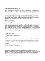
Figure 8: Performance increases from Hyper-
Threading Technology on an OLTP workload
Figure 8 shows the online transaction processing
performance, scaling from a single-processor
configuration through to a 4-processor system with
Hyper-Threading Technology enabled. This graph is
normalized to the performance of the single-processor
system.
T
t
can be seen that there is a significant overall
performance gain attributable to Hyper-Threading
Technology, 21% in the cases of the single and dual-
processor systems.
No Hyper-Threading Hyper-Threading Enabled
1.4
1.2
1
0.8
0.6
0.4
0.2
0
Webserver
Workload (1)
Webserver
Workload (2)
Server-side Java
workload
T
n
tel
and Pentium are registered trademarks of
T
nt
el
Corporation or its subsidiaries in the United States and
other countries.
Xeon is a trademark of
T
n
tel
Corporation or its
subsidiaries in the United States and other countries.
Figure 9: Web server benchmark performance
Figure 9 shows the benefit of Hyper-Threading
Technology when executing other server-centric
benchmarks. The workloads chosen were two different
benchmarks that are designed to exercise data and Web
server characteristics and a workload that focuses on
exercising a server-side Java environment.
T
n these
cases the performance benefit ranged from 16 to 28%.
All the performance results quoted above are
normalized to ensure that readers focus on the relative
performance and not the absolute performance.
Performance tests and ratings are measured using
specific computer systems and/or components and
reflect the approximate performance of
T
nt
el
products as
measured by those tests. Any difference in system
hardware or software design or configuration may affect
actual performance. Buyers should consult other
sources of information to evaluate the performance of
systems or components they are considering purchasing.
For more information on performance tests and on the
performance of
T
nt
el
products, refer to
www
www
.
.
i
i
n
n
t
t
e
e
l
l
.co
.co
m
m
/
/
p
p
r
r
oc
oc
s
s
/
/
pe
pe
rf
rf
/
/
limi
limi
t
t
s
s
.h
.h
t
t
m
m or call (U.S.) 1-
800-628-8686 or 1-916-356-3104
CONCLUSION
T
n
tel
’s Hyper-Threading Technology brings the concept
of simultaneous multi-threading to the
T
nt
el
Architecture. This is a significant new technology
direction for
T
n
te
l’s future processors.
T
t
will become
increasingly important going forward as it adds a new
technique for obtaining additional performance for
lower transistor and power costs.
The first implementation of Hyper-Threading
Technology was done on the
T
n
tel
Xeon
processor
MP.
T
n this implementation there are two logical
processors on each physical processor. The logical
processors have their own independent architecture
state, but they share nearly all the physical execution
and hardware resources of the processor. The goal was
to implement the technology at minimum cost while
ensuring forward progress on logical processors, even if
the other is stalled, and to deliver full performance even
when there is only one active logical processor. These
goals were achieved through efficient logical processor
selection algorithms and the creative partitioning and
recombining algorithms of many key resources.
Measured performance on the
Tntel
Xeon processor MP
with Hyper-Threading Technology shows performance
gains of up to 30% on common server application
benchmarks for this technology.
The potential for Hyper-Threading Technology is
tremendous; our current implementation has only just
T
nt
el
is a registered trademark of
T
n
tel
Corporation or
its subsidiaries in the United States and other countries.
Xeon is a trademark of
T
n
tel
Corporation or its
subsidiaries in the United States and other countries.
begun to tap into this potential. Hyper-Threading
Technology is expected to be viable from mobile
processors to servers; its introduction into market
segments other than servers is only gated by the
availability and prevalence of threaded applications and
workloads in those markets.
ACKNOWLEDGMENTS
Making Hyper-Threading Technology a reality was the
result of enormous dedication, planning, and sheer hard
work from a large number of designers, validators,
architects, and others. There was incredible teamwork
from the operating system developers, B
T
OS writers,
and software developers who helped with innovations
and provided support for many decisions that were
made during the definition process of Hyper-Threading
Technology. Many dedicated engineers are continuing
to work with our
T
SV partners to analyze application
performance for this technology. Their contributions
and hard work have already made and will continue to
make a real difference to our customers.
REFERENCES
A. Agarwal, B.H. Lim, D. Kranz and J. Kubiatowicz,
“APR
T
L: A processor Architecture for Multiprocessing,”
in Proceedings of the 17th Annual International
Symposium on Computer Architectures, pages 104-114,
May 1990.
R. Alverson, D. Callahan, D. Cummings, B. Koblenz,
A.
Porter, and B. Smith, “The TERA Computer System,” in
International Conference on Supercomputing, Pages 1 - 6,
June 1990.
L. A. Barroso et. al., “Piranha: A Scalable Architecture
Based on Single-Chip Multiprocessing,” in Proceedings
of the
27th Annual International Symposium on Computer
Architecture, Pages 282 - 293, June 2000.
M. Fillo, S. Keckler, W. Dally, N. Carter, A. Chang,
Y.
Gurevich, and W. Lee, “The M-Machine
Multicomputer,” in 28th Annual International
Symposium on Microarchitecture, Nov. 1995.
L. Hammond, B. Nayfeh, and K. Olukotun, “A Single-
Chip
Multiprocessor,” Computer, 30(9), 79 - 85, September
1997.
D. J. C. Johnson, “HP's Mako Processor,” Microprocessor
Forum, October 2001,
h tt
p://www .
cpu s .
h p .
c o
m / t
ec hn i ca l _ r
e f e r
e n ce s / m p f _2001 .
p
d f
B.J. Smith, “Architecture and Applications of the HEP
Multiprocessor Computer System,” in SPIE Real
Time Signal Processing IV, Pages 2 241 - 248, 1981.
J. M. Tendler, S. Dodson, and S. Fields, “POWER4 System
Microarchitecture,” Technical White Paper. IBM Server
Group, October 2001.
D. Tullsen, S. Eggers,
and H. Levy,
“Simultaneous
Multithreading:
Maximizing On-
chip Parallelism,” in
22nd Annual
International
Symposium on
Computer
Architecture, June
1995.
D. Tullsen, S. Eggers, J.
Emer, H. Levy, J.
Lo, and R. Stamm,
“Exploiting choice:
T
nstruction fetch and
issue on an
implementable
simultaneous
multithreading
processor,” in
23rd Annual
International
Symposium on
Computer
Architecture, May
1996.
Tntel
Corporation.
“TA-32
Tntel
Architecture
Software Developer’s
Manual, Volume 1:
Basic Architecture,”
Order number
245472, 2001
http://d e v e lop e r .
int e l .
c om/d e s ign/P e ntium4/
m a nu a ls
Tntel
Corporation.
“TA-32 Tntel
Architecture
Software
Developer’s
Manual, Volume
3: System
Programming
Guide,” Order
number 245472,
2001
h tt
p://d e v e l o
p e r
.
i n t
e l .
c o
m /d e s i g n
/P e n t
i u m 4/ m a n u
a l s
AU
TH
OR
S’
BI
OG
RA
PH
IE
S
Deborah T. Marr is
the CPU architect
responsible for Hyper-
Threading Technology
in the Desktop
Products Group.
Deborah has been at
T
n
tel
for over ten
years. She first joined
T
nt
el
in 1988 and
made significant
contributions to the
T
n
tel
386SX
processor, the P6
processor
microarchitecture, and
the
Tntel
®
Pentium
®
4
microarchitecture
development for the
next-generation
T
A-32 design. He was
appointed
T
nt
el
Fellow
in January
1999. He received
bachelor’s and
master’s degrees in
Electrical Engineering
from Brigham Young
University in 1982 and
1983, respectively.
His e-mail address is
g l
enn.h i
n t
on @i
n t
e l
.co
m
.
David A. Koufaty
received B.S. and M.S.
degrees from the
Simon Bolivar
University, Venezuela
in 1988 and
1991, respectively. He
then received a Ph.D.
degree in Computer
Science from the
University of
Tl
li
nois
at Urbana-Champaign
in 1997. For the last
three years he has
worked for the DPG
CPU Architecture
organization. His main
interests are in
multiprocessor
architecture and
software,
performance, and
compilation. His e-
mail address is
dav i
d.a.kou f
a t
y @i
n t
e l
.
co m
.
John (Alan) Miller
has worked at
T
n
tel
for over five years.
During that
time, he worked on
design and
architecture for the
Pentium
®
4
processor and
proliferation projects.
Alan obtained his M.S.
degree in Electrical
and Computer
Engineering from
Carnegie- Mellon
University. His e-mail
is
a l
an . mill e r
@
i n t
e l .co m.
Michael Upton is a
Principal
Engineer/Architect in
T
n
tel
’s Desktop
Platforms Group, and
is one of the
Processor
microarchitecture. Her
interests are in high-
architects of
the
T
nt
el
Pentium
4
process
or. He
performance
microarchitecture
and
performance analysis.
Deborah received her
B.S. degree in EECS
from the University of
California at Berkeley
in 1988, and her M.S.
degree in ECE from
Cornell University in
1992. Her e-mail
address is
debb i e . m a rr
@
i n t
e l .
co m.
Frank Binns
obtained a B.S.
degree in electrical
engineering from
Salford University,
England. He joined
T
nt
el
in 1984 after
holding research
engineering positions
with Marconi
Research Laboratories
and the Diamond
Trading Company
Research Laboratory,
both of the U.K. Frank
has spent the last 16
years with
T
nt
el
,
initially holding
technical management
positions in the
Development Tool,
Multibus Systems and
PC Systems divisions.
Frank’s last eight years
have been spent in the
Desktop Processor
Group in Technical
Marketing and
Processor
Architecture roles.
His e-mail
is
fr
a nk.b i
nns @i
n t
e l
.co m
.
Dave L. Hill joined
T
n
tel
in 1993 and was
the quad pumped bus
logic architect for
the Pentium
®
4
processor. Dave has
20 years industry
experience primarily
in high-
performance
memory
system
microarchitecture,
logic design, and
system debug. His e-
mail address is
dav i
d. l
.h ill@i
n t
e l
.co m
.
Glenn Hinton is an
T
nt
el
Fellow, Desktop
Platforms Group and
Director of
T
A-32
Microarchitecture
Development. He
is
responsible for
the
completed B.S. and
M.S. degrees in
Electrical
Engineering from the
University of
Washington in 1985
and 1990. After a
number of years in
T
C design and CAD
tool development, he
entered the University
of Michigan to
study computer
architecture. Upon
completion of his
Ph.D. degree in 1994,
he joined
T
n
tel
to work
on the Pentium
®
Pro
and Pentium 4
processors. His e-mail
address is
mi
k e.up t
on @i
n t
e l
.co m
.
Co
pyr
ight
©
T
n
te
l
Cor
por
atio
n
200
2.
Other names and
brands may be claimed
as the property of
others.
This
public
ation
was
downl
oaded
from
h tt
p : //
de v e l
ope r
. i
n t
e l .c
o m /
L
e
g
a
l
n
o
t
i
c
e
s
a
t
el.c
om/sites/corporate/trad
marx.ht
m
.