Tài liệu Image and Videl Comoression P9 doc
Bạn đang xem bản rút gọn của tài liệu. Xem và tải ngay bản đầy đủ của tài liệu tại đây (233.32 KB, 15 trang )
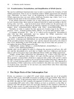
9
© 2000 by CRC Press LLC
Nonstandard Image Coding
In this chapter, we introduce three nonstandard image coding techniques: vector quantization (VQ)
(Nasrabadi and King, 1988), fractal coding (Barnsley and Hurd, 1993; Fisher, 1994; Jacquin, 1993),
and model-based coding (Li et al., 1994).
9.1 INTRODUCTION
The VQ, fractal coding, and model-based coding techniques have not yet been adopted as an image
coding standard. However, due to their unique features these techniques may find some special
applications. Vector quantization is an effective technique for performing data compression. The-
oretically, vector quantization is always better than scalar quantization because it fully exploits the
correlation between components within the vector. The optimal coding performance will be obtained
when the dimension of the vector approaches infinity, and then the correlation between all com-
ponents is exploited for compression. Another very attractive feature of image vector quantization
is that its decoding procedure is very simple since it only consists of table look-ups. However, there
are two major problems with image VQ techniques. The first is that the complexity of vector
quantization exponentially increases with the increasing dimensionality of vectors. Therefore, for
vector quantization it is important to solve the problem of how to design a practical coding system
which can provide a reasonable performance under a given complexity constraint. The second
major problem of image VQ is the need for a codebook, which causes several problems in practical
application such as generating a universal codebook for a large number of images, scaling the
codebook to fit the bit rate requirement, and so on. Recently, the lattice VQ schemes have been
proposed to address these problems (Li, 1997).
Fractal theory has a long history. Fractal-based techniques have been used in several areas of
digital image processing such as image segmentation, image synthesis, and computer graphics, but
only in recent years have they been extended to the applications of image compression (Jacquin,
1993).
A fractal is a geometric form which has the unique feature of having extremely high visual
self-similar irregular details while containing very low information content. Several methods for
image compression have been developed based on different characteristics of fractals. One method
is based on Iterated Function Systems (
IFS
) proposed by Barnsley (1988). This method uses the
self-similar and self-affine property of fractals. Such a system consists of sets of transformations
including translation, rotation, and scaling. On the encoder side of a fractal image coding system,
a set of fractals is generated from the input image. These fractals can be used to reconstruct the
image at the decoder side. Since these fractals are represented by very compact fractal transforma-
tions, they require very small amounts of data to be expressed and stored as formulas. Therefore,
the information needed to be transmitted is very small. The second fractal image coding method
is based on the fractal dimension (Lu, 1993; Jang and Rajala, 1990). Fractal dimension is a good
representation of the roughness of image surfaces. In this method, the image is first segmented
using the fractal dimension and then the resultant uniform segments can be efficiently coded using
the properties of the human visual system. Another fractal image coding scheme is based on fractal
geometry, which is used to measure the length of a curve with a yardstick (Walach, 1989). The
details of these coding methods will be discussed in Section 9.3.
The basic idea of model-based coding is to reconstruct an image with a set of model parameters.
The model parameters are then encoded and transmitted to the decoder. At the decoder the decoded
© 2000 by CRC Press LLC
model parameters are used to reconstruct the image with the same model used at the encoder.
Therefore, the key techniques in the model-based coding are image modeling, image analysis, and
image synthesis.
9.2 VECTOR QUANTIZATION
9.2.1 B
ASIC
P
RINCIPLE
OF
V
ECTOR
Q
UANTIZATION
An N-level vector quantizer,
Q
, is mapping from a
K
-dimensional vector set {
V
}, into a finite
codebook,
W
= {
w
1
,
w
2
, …,
w
N
}:
Q: V
Æ
W
(9.1)
In other words, it assigns an input vector,
v
, to a representative vector (codeword),
w
from a
codebook,
W
. The vector quantizer,
Q
, is completely described by the codebook,
W
= {
w
1
,
w
2
, …,
w
N
}, together with the disjoint partition,
R
= {
r
1
,
r
2
, …,
r
N
}, where
r
i
= {
v
:
Q
(
v
) =
w
i
} (9.2)
and
w
and
v
are
K
-dimensional vectors. The partition should identically minimize the quantization
error (Gersho, 1982). A block diagram of the various steps involved in image vector quantization
is depicted in Figure 9.1.
The first step in image vector quantization is the image formation. The image data are first
partitioned into a set of vectors. A large number of vectors from various images are then used to
form a training set. The training set is used to generate a codebook, normally using an iterative
clustering algorithm. The quantization or coding step involves searching each input vector for the
closest codeword in the codebook. Then the corresponding index of the selected codeword is coded
and transmitted to the decoder. At the decoder, the index is decoded and converted to the corre-
sponding vector with the same codebook as at the encoder by look-up table. Thus, the design
decisions in implementing image vector quantization include (1) vector formation; (2) training set
generation; (3) codebook generation; and (4) quantization.
9.2.1.1 Vector Formation
The first step of vector quantization is vector formation; that is, the decomposition of the images
into a set of vectors. Many different decompositions have been proposed; examples include the
FIGURE 9.1
Principle of image vector quantization. The dashed lines correspond to training set generation,
codebook generation, and transmission (if it is necessary).
© 2000 by CRC Press LLC
intensity values of a spatially contiguous block of pixels (Gersho and Ramamuthi, 1982; Baker
and Gray, 1983); these same intensity values, but now normalized by the mean and variance of the
block (Murakami et al., 1982); the transformed coefficients of the block pixels (Li and Zhang,
1995); and the adaptive linear predictive coding coefficients for a block of pixels (Sun, 1984).
Basically, the approaches of vector formation can be classified into two categories: direct spatial
or temporal, and feature extraction. Direct spatial or temporal is a simple approach to forming
vectors from the intensity values of a spatial or temporal contiguous block of pixels in an image
or an image sequence. A number of image vector quantizaton schemes have been investigated with
this method. The other method is feature extraction. An image feature is a distinguishing primitive
characteristic. Some features are natural in the sense that they are defined by the visual appearance
of an image, while the other so-called artificial features result from specific manipulations or
measurements of images or image sequences. In vector formation, it is well known that the image
data in a spatial domain can be converted to a different domain so that subsequent quantization
and joint entropy encoding can be more efficient. For this purpose, some features of image data,
such as transformed coefficients and block means can be extracted and vector quantized. The
practical significance of feature extraction is that it can result in the reduction of vector size,
consequently reducing the complexity of coding procedure.
9.2.1.2 Training Set Generation
An optimal vector quantizer should ideally match the statistics of the input vector source. However,
if the statistics of an input vector source are unknown, a training set representative of the expected
input vector source can be used to design the vector quantizer. If the expected vector source has a
large variance, then a large training set is needed. To alleviate the implementation complexity
caused by a large training set, the input vector source can be divided into subsets. For example, in
(Gersho, 1982) the single input source is divided into “edge” and “shade” vectors, and then the
separate training sets are used to generate the separate codebooks. Those separate codebooks are
then concatenated into a final codebook. In other methods, small local input sources corresponding
to portions of the image are used as the training sets, thus the codebook can better match the local
statistics. However, the codebook needs to be updated to track the changes in local statistics of the
input sources. This may increase the complexity and reduce the coding efficiency. Practically, in
most coding systems a set of typical images is selected as the training set and used to generate the
codebook. The coding performance can then be insured for the images with the training set, or for
those not in the training set but with statistics similar to those in the training set.
9.2.1.3 Codebook Generation
The key step in conventional image vector quantization is the development of a good codebook.
The optimal codebook, using the mean squared error (MSE) criterion, must satisfy two necessary
conditions (Gersho, 1982). First, the input vector source is partitioned into a predecided number
of regions with the minimum distance rule. The number of regions is decided by the requirement
of the bit rate, or compression ratio and coding performance. Second, the codeword or the repre-
sentative vector of this region is the mean value, or the statistical center, of the vectors within the
region. Under these two conditions, a generalized Lloyd clustering algorithm proposed by Linde,
Buzo, and Gray (1980) — the so-called LBG algorithm — has been extensively used to generate
the codebook. The clustering algorithm is an iterative process, minimizing a performance index
calculated from the distances between the sample vectors and their cluster centers. The LBG
clustering algorithm can only generate a codebook with a local optimum, which depends on the
initial cluster seeds. Two basic procedures have been used to obtain the initial codebook or cluster
seeds. In the first approach, the starting point involves finding a small codebook with only two
codewords, and then recursively splitting the codebook until the required number of codewords is
© 2000 by CRC Press LLC
obtained. This approach is referred to as binary splitting. The second procedure starts with initial
seeds for the required number of codewords, these seeds being generated by preprocessing the
training sets. To address the problem of a local optimum, Equitz (1989) proposed a new clustering
algorithm, the pairwise nearest neighbor (PNN) algorithm. The PNN algorithm begins with a
separate cluster for each vector in the training set and merges together two clusters at a time until
the desired codebook size is obtained. At the beginning of the clustering process, each cluster
contains only one vector. In the following process the two closest vectors in the training set are
merged to their statistical mean value, in such a way the error incurred by replacing these two
vectors with a single codeword is minimized. The PNN algorithm significantly reduces computa-
tional complexity without sacrificing performance. This algorithm can also be used as an initial
codebook generator for the LBG algorithm.
9.2.1.4 Quantization
Quantization in the context of a vector quantization involves selecting a codeword in the codebook
for each input vector. The optimal quantization, in turn, implies that for each input vector,
v
, the
closest codeword,
w
i
, is found as shown in Figure 9.2. The measurement criterion could be mean
squared error, absolute error, or other distortion measures.
A full-search quantization is an exhaustive search process over the entire codebook for finding
the closest codeword, as shown in Figure 9.3(a). It is optimal for the given codebook, but the
computation is more expensive. An alternative approach is a tree-search quantization, where the
search is carried out based on a hierarchical partition. A binary tree search is shown in Figure 9.3(b).
A tree search is much faster than a full search, but it is clear that the tree search is suboptimal for
the given codebook and requires more memory for the codebook.
FIGURE 9.2
Principle of vector quantization.
FIGURE 9.3
(a) Full search quantization; (b) binary tree search quantization.
© 2000 by CRC Press LLC
9.2.2 S
EVERAL
I
MAGE
C
ODING
S
CHEMES
WITH
V
ECTOR
Q
UANTIZATION
In this section, we are going to present several image coding schemes using vector quantization
which include residual vector quantization, classified vector quantization, transform domain vector
quantization, predictive vector quantization, and block truncation coding (BTC) which can be seen
as a binary vector quantization.
9.2.2.1 Residual VQ
In the conventional image vector quantization, the vectors are formed by spatially partitioning the
image data into blocks of 8
¥
8 or 4
¥
4 pixels. In the original spatial domain the statistics of
vectors may be widely spread in the multidimensional vector space. This causes difficulty in
generating the codebook with a finite size and limits the coding performance. Residual VQ is
proposed to alleviate this problem. In residual VQ, the mean of the block is extracted and coded
separately. The vectors are formed by subtracting the block mean from the original pixel values.
This scheme can be further modified by considering the variance of the blocks. The original blocks
are converted to the vectors with zero mean and unit standard deviation with the following con-
version formula (Murakami et al., 1982):
(9.3)
(9.4)
(9.5)
where
m
i
is the mean value of
i
th block,
s
i
is the variance of
i
th block,
s
j
is the pixel value of pixel
j
(
j
= 0, …,
K
-1) in the
i
th block,
K
is the total number of pixels in the block, and
x
j
is the normalized
value of pixel
j
. The new vector
X
i
is now formed by
x
j
(
j
= 0, 1, …,
k
-1):
X
i
= [
x
0
,
x
1
, …,
x
K
]
i
(9.6)
With the above normalization the probability function
P
(
X
) of input vector
X
is approximately
similar for image data from different scenes. Therefore, it is easy to generate a codebook for the
new vector set. The problem with this method is that the mean and variance values of blocks have
to be coded separately. This increases the overhead and limits the coding efficiency. Several methods
have been proposed to improve the coding efficiency. One of these methods is to use predictive
coding to code the block mean values. The mean value of the current block can be predicted by
one of the previously coded neighbors. In such a way, the coding efficiency increases as the use
of interblock correlation.
9.2.2.2 Classified VQ
In image vector quantization, the codebook is usually generated using training set under constraint
of minimizing the mean squared error. This implies that the codeword is the statistical mean of the
m
K
s
ij
j
k
=
=
-
Â
1
0
1
x
sm
j
ji
i
=
-
()
s
s
iji
j
K
K
sm=-
()
È
Î
Í
Í
˘
˚
˙
˙
=
-
Â
1
2
0
1
1
2
© 2000 by CRC Press LLC
region. During quantization, each input vector is replaced by its closest codeword. Therefore, the
coded images usually suffer from edge distortion at very low bit rates, since edges are smoothed
by the operation of averaging with the small-sized codebook. To overcome this problem, we can
classify the training vector set into edge vectors and shade vectors (Gersho, 1982). Two separate
codebooks can then be generated with the two types of training sets. Each input vector can be
coded by the appropriate codeword in the codebook. However, the edge vectors can be further
classified into many types according to their location and angular orientation. The classified VQ
can be extended into a system which contains many sub-codebooks, each representing a type of
edge. However, this would increase the complexity of the system and would be hard to implement
in practical applications.
9.2.2.3 Transform Domain VQ
Vector quantization can be performed in the transform domain. A spatial block of 4
¥
4 or 8
¥
8
pixels is first transformed to the 4
¥
4 or 8
¥
8 transformed coefficients. There are several ways to
form vectors with transformed coefficients. In the first method, a number of high-order coefficients
can be discarded since most of the energy is usually contained in the low-order coefficients for
most blocks. This reduces the VQ computational complexity at the expense of a small increase in
distortion. However, for some active blocks, the edge information is contained in the high frequen-
cies, or high-order coefficients. Serious subjective distortion will be caused by discarding high
frequencies. In the second method, the transformed coefficients are divided into several bands and
each band is used to form its corresponding vector set. This method is equivalent to the classified
VQ in spatial domain. An adaptive scheme is then developed by using two kinds of vector formation
methods. The first method is used for the blocks containing the moderate intensity variation and
the second method is used for the blocks with high spatial activities. However, the complexity
increases as more codebooks are needed in this kind of adaptive coding system.
9.2.2.4 Predictive VQ
The vectors are usually formed by the spatially consecutive blocks. The consecutive vectors are
then highly statistically dependent. Therefore, better coding performance can be achieved if the
correlation between vectors is exploited. Several predictive VQ schemes have been proposed to
address this problem. One kind of predictive VQ is finite state VQ (Foster et al., 1985). The finite-
state VQ is similar to a trellis coder. In the finite state VQ, the codebook consists of a set of sub-
codebooks. A state variable is then used to specify which sub-codebook should be selected for
coding the input vector. The information about the state variable must be inferred from the received
sequence of state symbols and initial state such as in a trellis coder. Therefore, no side information
or no overhead need be transmitted to the decoder. The new encoder state is a function of the
previous encoder state and the selected sub-codebook. This permits the decoder to track the encoder
state if the initial condition is known. The finite-state VQ needs additional memory to store the
previous state, but it takes advantage of correlation between successive input vectors by choosing
the appropriate codebook for the given past history. It should be noted that the minimum distortion
selection rule of conventional VQ is not necessary optimum for finite-state VQ for a given decoder
since a low-distortion codeword may lead to a bad state and hence to poor long-term behavior.
Therefore, the key design issue of finite-state VQ is to find a good next-state function.
Another predictive VQ was proposed by Hang and Woods (1985). In this system, the input
vector is formed in such a way that the current pixel is as the first element of the vector and the
previous inputs as the remaining elements in the vector. The system is like a mapping or a recursive
filter which is used to predict the next pixel. The mapping is implemented by a vector quantizer
look-up table and provides the predictive errors.
© 2000 by CRC Press LLC
9.2.2.5 Block Truncation Coding
In the block truncation code (BTC) (Delp and Mitchell, 1979), an image is first divided into 4
¥
4
blocks. Each block is then coded individually. The pixels in each block are first converted into two-
level signals by using the first two moments of the block:
(9.7)
where
m
is the mean value of the block,
s
is the standard deviation of the block,
N
is the number
of total pixels in the block, and
q
is the number of pixels which are greater in value than
m
.
Therefore, each block can be described by the values of block mean, variance, and a binary-bit
plane which indicates whether the pixels have values above or below the block mean. The binary-
bit plane can be seen as a binary vector quantizer. If the mean and variance of the block are
quantized to 8 bits, then 2 bits per pixel is achieved for blocks of 4
¥
4 pixels. The conventional
BTC scheme can be modified to increase the coding efficiency. For example, the block mean can
be coded by a DPCM coder which exploits the interblock correlation. The bit plane can be coded
with an entropy coder on the patterns (Udpikar and Raina, 1987).
9.2.3 L
ATTICE
VQ
FOR
I
MAGE
C
ODING
In conventional image vector quantization schemes, there are several issues, which cause some
difficulties for the practical application of image vector quantization. The first problem is the
limitation of vector dimension. It has been indicated that the coding performance of vector quan-
tization increases as the vector dimension while the coding complexity exponentially increases at
the same time as the increasing vector dimension. Therefore, in practice only a small vector
dimension is possible under the complexity constraint. Another important issue in VQ is the need
for a codebook. Much research effort has gone into finding how to generate a codebook. However,
in practical applications there is another problem of how to scale the codebook for various rate-
distortion requirements. The codebook generated by LBG-like algorithms with a training set is
usually only suitable for a specified bit rate and does not have the flexibility of codebook scalability.
For example, a codebook generated for an image with small resolution may not be suitable for
images with high resolution. Even for the same spatial resolution, different bit rates would require
different codebooks. Additionally, the VQ needs a table to specify the codebook and, consequently,
the complexity of storing and searching is too high to have a very large table. This further limits
the coding performance of image VQ.
These problems become major obstacles for implementing image VQ. Recently, an algorithm
of lattice VQ has been proposed to address these problems (Li et al., 1997). Lattice VQ does not
have the above problems. The codebook for lattice VQ is simply a collection of lattice points
uniformly distributed over the vector space. Scalability can be achieved by scaling the cell size
associated with every lattice point just like in the scalar quantizer by scaling the quantization step.
The basic concept of the lattice can be found in (Conway and Slone, 1991). A typical lattice VQ
scheme is shown in Figure 9.4. There are two steps involved in the image lattice VQ. The first step
is to find the closest lattice point for the input vector. The second step is to label the lattice point,
i.e., mapping a lattice point to an index. Since lattice VQ does need a codebook, the index assignment
is based on a lattice labeling algorithm instead of a look-up table such as in conventional VQ.
Therefore, the key issue of lattice VQ is to develop an efficient lattice-labeling algorithm. With this
am
q
Nq
bm
N
q
=+
-
=-
-
s
s
1
© 2000 by CRC Press LLC
algorithm the closest lattice point and its corresponding index within a finite boundary can be
obtained by a calculation at the encoder for each input vector.
At the decoder, the index is converted to the lattice point by the same labeling algorithm. The
vector is then reconstructed with the lattice point. The efficiency of a labeling algorithm for lattice
VQ is measured by how many bits are needed to represent the indices of the lattice points within
a finite boundary. We use a two-dimensional lattice to explain the lattice labeling efficiency. A two-
dimensional lattice is shown in Figure 9.5.
In Figure 9.5, there are seven lattice points. One method used to label these seven 2-D lattice
points is to use their coordinates (
x,y
) to label each point. If we label
x
and
y
separately, we need
two bits to label three values of
x
and three bits to label a possible five values of
y
, and need a total
of five bits. It is clear that three bits are sufficient to label seven lattice points. Therefore, different
labeling algorithms may have different labeling efficiency. Several algorithms have been developed
for multidimensional lattice labeling. In (Conway, 1983), the labeling method assigns an index to
every lattice point within a Voronoi boundary where the shape of the boundary is the same as the
shape of Voronoi cells. Apparently, for different dimension, the boundaries have different shapes.
In the algorithm proposed in (Laroia, 1993), the same method is used to assign an index to each
lattice point. Since the boundaries are defined by the labeling algorithm, this algorithm might not
achieve a 100% labeling efficiency for a prespecified boundary such as a pyramid boundary. The
algorithm proposed by Fischer (1986) can assign an index to every lattice point within a prespecified
pyramid boundary and achieves a 100% labeling efficiency, but this algorithm can only be used
for the Z
n
lattice. In a recently proposed algorithm (Wang et al., 1998), the technical breakthrough
was obtained. In this algorithm a labeling method was developed for Construction-A and Construc-
tion-B lattices (Conway, 1983), which is very useful for VQ with proper vector dimensions, such
as 16, and achieves 100% efficiency. Additionally, these algorithms are used for labeling lattice
FIGURE 9.4
Block diagram of lattice VQ.
FIGURE 9.5
Labeling a two-dimensional lattice.
© 2000 by CRC Press LLC
points with 16 dimensions and provide minimum distortion. These algorithms were developed
based on the relationship between lattices and linear block codes. Construction-A and Construction-
B are the two simplest ways to construct a lattice from a binary linear block code C = (n, k, d),
where n, k, and d are the length, the dimension, and the minimum distance of the code, respectively.
A Construction-A lattice is defined as:
(9.8)
where
Z
n
is the
n
-dimensional cubic lattice and
C
is a binary linear block code. There are two steps
involved for labeling a Construction-A lattice. The first is to order the lattice points according to
the binary linear block code
C
, and then to order the lattice points associated with a particular
nonzero binary codeword. For the lattice points associated with a nonzero binary codeword, two
sub-lattices are considered separately. One sub-lattice consists of all the dimensions that have a
“0” component in the binary codeword and the other consists of all the dimensions that have a “1”
component in the binary codeword. The first sub-lattice is considered as a 2Z lattice while the
second is considered as a translated 2Z lattice. Therefore, the labeling problem is reduced to labeling
the Z lattice at the final stage.
A Construction-B lattice is defined as:
(9.9)
where
D
n
is an
n
-dimensional Construction-A lattice with the definition as:
(9.10)
and
C
is a binary doubly even linear block code. When
n
is equal to 16, the binary even linear
block code associated with
L
16
is
C
= (16, 5, 8). The method for labeling a Construction-B lattice
is similar to the method for labeling a Construction-A lattice with two minor differences. The first
difference is that for any vector
y
=
c
+ 2x, x ΠZ
n
, if y is a Construction-A lattice point; and x Œ
D
n
, if y is a Construction-B lattice point. The second difference is that C is a binary doubly even
linear block code for Construction-B lattices while it is not necessarily doubly even for Construc-
tion-A lattices. In the implementation of these lattice point labeling algorithms, the encoding and
decoding functions for lattice VQ have been developed in (Li et al., 1997). For a given input vector,
an index representing the closest lattice point will be found by the encoding function, and for an
input index the reconstructed vector will be generated by the decoding function. In summary, the
idea of lattice VQ for image coding is an important achievement in eliminating the need for a
codebook for image VQ. The development of efficient algorithms for lattice point labeling makes
lattice VQ feasible for image coding.
9.3 FRACTAL IMAGE CODING
9.3.1 M
ATHEMATICAL FOUNDATION
A fractal is a geometric form whose irregular details can be represented by some objects with
different scale and angle, which can be described by a set of transformations such as affine
transformations. Additionally, the objects used to represent the image’s irregular details have some
form of self-similarity and these objects can be used to represent an image in a simple recursive
way. An example of fractals is the Von Koch curve as shown in Figure 9.6. The fractals can be
used to generate an image. The fractal image coding that is based on iterated function systems
L
n
n
CZ=+2
L
nn
CD=+2
Dnn Z
n
n
=-
()
+,,12 2
© 2000 by CRC Press LLC
(IFS) is the inverse process of image generation with fractals. Therefore, the key technology of
fractal image coding is the generation of fractals with an IFS.
To explain IFS, we start from the contractive affine transformation. A two-dimensional affine
transformation A is defined as follows:
(9.11)
This is a transformation which consists of a linear transformation followed by a shift or translation,
and maps points in the Euclidean plane into new points in the another Euclidean plane. We define
that a transformation is contractive if the distance between two points P
1
and P
2
in the new plane
is smaller than their distance in the original plane, i.e.,
(9.12)
where s is a constant and 0 < s < 1. The contractive transformations have the property that when
the contractive transformations are repeatedly applied to the points in a plane, these points will
converge to a fixed point. An iterated function system (IFS) is defined as a collection of contractive
affine transformations. A well-known example of IFS contains four following transformations:
(9.13)
This is the IFS of a fern leaf, whose parameters are shown in Table 9.1.
The transformation A
1
is used to generate the stalk, the transformation A
2
is used to generate
the right leaf, the transformation A
3
is used to generate the left leaf, and the transformation A
4
is
used to generate main fern. A fundamental theorem of fractal geometry is that each IFS defines a
unique fractal image. This image is referred to as the attractor of the IFS. In other words, an image
corresponds to the attractor of an IFS. Now let us explain how to generate the image using the IFS.
Let us suppose that an IFS contains N affine transformations, A
1
, A
2
, … A
N
, and each transformation
has an associated probability, p
1
, p
2
, …, p
N
, respectively. Suppose that this is a complete set and
the sum of the probability equals to 1, i.e.,
FIGURE 9.6 Construction of the Von Koch curve.
A
x
y
ab
cd
x
y
e
f
È
Î
Í
˘
˚
˙
=
È
Î
Í
˘
˚
˙
È
Î
Í
˘
˚
˙
+
È
Î
Í
˘
˚
˙
dAP AP sdPP
12 12
() ()
()
<
()
,,
A
x
y
ab
cd
x
y
e
f
i
i
È
Î
Í
˘
˚
˙
=
È
Î
Í
˘
˚
˙
È
Î
Í
˘
˚
˙
+
È
Î
Í
˘
˚
˙
= , , , .1234
© 2000 by CRC Press LLC
p
1
+ p
2
+…+ p
N
= 1 and p
i
> 0 for i = 0, 1, …, N. (9.14)
The procedure for generating an attractor is as follows. For any given point (x
0
, y
0
) in a Euclidean
plane, one transformation in the IFS according to its probability is selected and applied to this
point to generate a new point (x
1
, y
1
). Then another transformation is selected according to its
probability and applied to the point (x
1
,y
1
) to obtain a new point (x
2
,y
2
). This process is repeated
over and over again to obtain a long sequence of points: (x
0
,y
0
), (x
1
,y
1
), …, (x
n
,y
n
), …. According
to the theory of iterated function systems, these points will converge to an image that is the attractor
of the given IFS. The above-described procedure is shown in the flowchart of Figure 9.7. With the
above algorithm and the parameters in Table 9.1, initially the point can be anywhere within the
large square, but after several iterations it will converge onto the fern. The 2-D affine transformations
are extended to 3-D transformations, which can be used to create fractal surfaces with the iterated
function systems. This fractal surface can be considered as the gray level or brightness of a 2-D
image.
9.3.2 IFS-BASED FRACTAL IMAGE CODING
As described in the last section, an IFS can be used to generate a unique image, which is referred
to as an attractor of the IFS. In other words, this image can be simply represented by the parameters
of the IFS. Therefore, if we can use an inverse procedure to generate a set of transformations, i.e.,
TABLE 9.1
The Parameters of the IFS of a Fern Leaf
abcdef
A
1
0 0 0 0.16 0 0.2
A
2
0.2 –0.26 0.23 0.22 0 0.2
A
3
–0.15 0.28 0.26 0.24 0 0.2
A
4
0.85 0.04 –0.04 0.85 0 0.2
FIGURE 9.7 Flowchart of image generation
with an IFS.
© 2000 by CRC Press LLC
an IFS from an image, then these transformations or the IFS can be used to represent the approx-
imation of the image. The image coding system can use the parameters of the transformations in
the IFS instead of the original image data for storage or transmission. Since the IFS contains only
very limited data such as transformation parameters, this image coding method may result in a
very high compression ratio. For example, the fern image is represented by 24 integers or 192 bits
(if each integer is represented by 8 bits). This number is much smaller than the number needed to
represent the fern image pixel by pixel. Now the key issue of the IFS-based fractal image coding
is to generate the IFS for the given input image. Three methods have been proposed to obtain the
IFS (Lu, 1993). One is the direct method, that directly finds a set of contractive affine transforma-
tions from the image based on the self-similarity of the image. The second method is to partition
an image into the smaller objects whose IFSs are known. These IFSs are used to form a library.
The encoding procedure is to look for an IFS from the library for each small object. The third
method is called partitioned IFS (PIFS). In this method, the image is first divided into smaller
blocks and then the IFS for each block is found by mapping a larger block into a small block.
In the direct approach, the image is first partitioned into nonoverlapped blocks in such a way
that each block is similar to the whole image and a transformation can map the whole image to
the block. The transformation for each individual block may be different. The combination of these
transformations can be taken as the IFS of the given image. Then much fewer data are required to
represent the IFS or the transformations than to transmit or store the given image in the pixel by
pixel way. For the second approach, the key issue is how to partition the given image into objects
whose IFSs are known. The image processing techniques such as color separation, edge detection,
spectrum analysis, and texture variation analysis can be used for image partitioning. However, for
natural images or arbitrary images, it may be impossible or very difficult to find an IFS whose
attractor perfectly covers the original image. Therefore, for most natural images the partitioned IFS
method has been proposed (Lu, 1993). In this method, the transformations do not map the whole
image into small block. For encoding an image, the whole image is first partitioned into a number
of larger blocks that are referred to as domain blocks. The domain blocks can be overlapped. Then
the image is partitioned into a number of smaller blocks that are called as range blocks. The range
blocks do not overlap and the sum total of the range blocks covers the whole image. In the third
step, a set of contractive transformations is chosen. Each range block is mapped into a domain
block with a searching method and a matching criterion. The combination of the transformations
is used to form a partitioned IFS (PIFS). The parameters of PIFS are transmitted to the decoder.
It is noted that no domain blocks are transmitted. The decoding starts with a flat background. The
iterated process is then applied with the set of transformations. The reconstructed image is then
obtained after the process converges. From the above discussion, it is found that there are three
main design issues involved in the block fractal image coding system. First are partitioning
techniques which include range block partitioning and domain block partitioning. As mentioned
earlier, the domain block is larger than the range block. Dividing the image into square blocks is
the simplest partitioning approach. The second issue is the choice of distortion measurement and
a searching method. The common distortion measurement in the block fractal image coding is the
root mean square (RMS) error. The closest match between the range block and transformed domain
block is found by the RMS distortion measurement. The third method is the selection of a set of
contractive transformations defined consistently with a partition.
It is noted that the partitioned IFS (PIFS)-based fractal image coding has several similar features
with image vector quantization. Both coding schemes are block-based coding schemes and need a
codebook for encoding. For PIFS-based fractal image coding the domain blocks can be seen as
forming a virtual codebook. One difference is that the fractal image coding does not need to transmit
the codebook data (domain blocks) to the decoder while VQ does. The second difference is the
block size. For VQ, block size for the code vector and input vector is the same while in PIFS
fractal coding the size of the domain block is different from the size of the range blocks. Another
© 2000 by CRC Press LLC
difference is that in fractal image coding the image itself serves as the codebook, while this is not
true for VQ image coding.
9.3.3 OTHER FRACTAL IMAGE CODING METHODS
Besides the IFS-based fractal image coding, there are several other fractal image coding methods.
One is the segmentation-based coding scheme using fractal dimensions. In this method, the image
is segmented into regions based on the properties of the human visual system (HVS). The image
is segmented into the regions, each of these regions is homogeneous in the sense of having similar
features by visual perception. This is different from the traditional image segmentation techniques
that try to segment an image into regions of constant intensity. For a complicated image, good
representation of an image needs a large number of small segmentations. However, in order to
obtain a high compression ratio, the number of segmentations is limited. The trade-off between
image quality and bit rate has to be considered. A parameter, fractal dimension, is used as a measure
to control the trade-off. Fractal dimension is a characteristic of a fractal. It is related to a metric
property such as the length of a curve and the area of a surface. The fractal dimension can provide
a good measurement of the perceptual roughness of the curve and surface. For example, if we use
many segments of straight lines to approximate a curve, by increasing the length of the straight
lines perceptually rougher curves are represented.
9.4 MODEL-BASED CODING
9.4.1 B
ASIC CONCEPT
In the model-based coding, an image model that can be a 2-D model for still images or a 3-D
model for video sequence is first constructed. At the encoder, the model is used to analyze the
input image. The model parameters are then transmitted to the decoder. At the decoder the recon-
structed image is synthesized by the model parameters, with the same image model used at the
encoder. This basic idea of model-based coding is shown in the Figure 9.8. Therefore, the basic
techniques in the model-based coding are the image modeling, image analysis, and image synthesis
techniques. Both image analysis and synthesis are based on the image model. The image modeling
techniques used for image coding can normally be divided into two classes: structure modeling
and motion modeling. Motion modeling is usually used for video sequences and moving pictures,
while structure modeling is usually used for still image coding. The structure model is used for
reconstruction of a 2-D or 3-D scene model.
FIGURE 9.8 Basic principle of model-based coding.
© 2000 by CRC Press LLC
9.4.2 IMAGE MODELING
The geometric model is usually used for image structure description. The geometric model can be
classified into a surface-based description and volume-based description. The major advantage of
surface description is that such description is easily converted into a surface representation that can
be encoded and transmitted. In these models the surface is approximated by planar polygonal
patches such as triangle patches. The surface shape is represented by a set of points that represent
the vertices of these triangle meshes. The size of these triangle patches can be adjusted according
to the surface complexity. In other words, for more complicated areas, more triangle meshes are
needed to approximate the surface while for smoothing areas, the mesh sizes can be larger or less
vertices of the triangle meshes are needed to represent the surface. The volume-based description
is a natural approach for modeling most solid world objects. Most existing research work on volume-
based description focuses on the parametric volume description. The volume-based description is
used for 3-D objects or video sequences.
However, model-based coding is successfully applicable only to certain kinds of images since
it is very hard to find general image models suitable for most natural scenes. The few successful
examples of image models include the human face, head, and body. These models are developed
for the analysis and synthesis of moving images. The face animation has been adopted for the
MPEG-4 visual coding. The body animation is under consideration for version 2 of MPEG-4 visual
coding.
9.5 SUMMARY
In this chapter three kinds of image coding techniques, vector quantization, fractal image coding,
and model-based coding, which are not used in the current standards, have been presented. All
three techniques have several important features such as very high compression ratios for certain
kinds of images and very simple decoding procedures (especially for VQ). However, due to some
limitations these techniques have not been adopted by industry standards. It should be noted that
recently the facial model face animation technique has been adopted for the MPEG-4 visual standard
(mpeg4 visual).
9.6 EXERCISES
9-1. In the modified residual VQ described in Equation 9.5, with a 4 ¥ 4 block and 8 bits for
each pixel of original image, we use 8 bits for coding block mean and block variance.
We want to obtain the final bit rate of 2 bits per pixel. What codebook size do we have
to use for the coding residual, assuming that we use fixed-length coding to code vector
indices?
9-2. In the block truncation coding described in Equation 9.7, what is the bit rate for a block
size of 4 ¥ 4 if the mean and variance are both encoded with 8 bits? Do you have any
suggestions for reducing the bit rate without seriously affecting the reconstruction quality?
9-3. Is the codebook generated with the LBG algorithm local optimum? List the several
important factors that will affect the quality of codebook generation.
9-4. In image coding using VQ, what kind of problems will be caused by using the codebook
in practical applications (hint: changing bit rate).
9-5. What is the most important improvement of the lattice VQ over traditional VQ in practical
application. What is the key issue for lattice VQ for image coding application?
9-6. Write a subroutine to generate a fern leaf (using C).
© 2000 by CRC Press LLC
REFERENCES
Baker, R. L. and R. M. Gray, Image compression using nonadaptive spatial vector quantization, ISCAS’83,
1983, 55-61.
Barnsley, M.F. and A.E. Jacquin, Application of recurrent iterated function systems, SPIE, vol. 1001, Visual
Communications and Image Processing, 1988, 122-131.
Barnsley, M. and L. P. Hurd, Fractal Image Compression, A.K. Peters, Wellesley, MA, 1993.
Conway, J. H. and N. J. A. Slone, A fast encoding method for lattice codes and quantizers, IEEE Trans. Inform.
Theory, vol. IT-29, 820-824, 1983.
Conway, J. H. and N. J. A. Slone, Sphere Packings, Lattices and Groups, New York: Springer-Verlag, 1991.
Delp, E. J. and D. R. Mitchell, Image compression using block truncation coding, IEEE Trans. Commun.,
COM-27, 1979.
Dunham, M. and R. Gray, An algorithm for the design of labelled-transition finite-state vector quantizer, IEEE
Trans. Commun., COM-33, 83-89, 1985.
Equits, W. H. A new vector quantization clustering algorithm, IEEE Trans. Acoust. Speech Signal Process.,
37, 1568-1575, 1989.
Fischer, T. R., A paramid vector quantization, IEEE Trans. Inform. Theory, vol. IT-32, 568-583, 1986.
Fisher, Y. Fractal Image Compression — Theory and Application, New York: Springer-Verlag, 1994.
Foster, J., R. M. Gray, and M. O. Dunham, Finite-state vector quantization for waveform coding, IEEE Trans.
Inf. Theory, IT-31, 348-359, 1985.
Gersho, A. and B. Ramamurthi, Image coding using vector quantization, ICASSP’82, Paris, May 1982, 428-431.
Gersho, A. On the structure of vector quantizer, IEEE Trans. Inf. Theory, IT-28, 157-166, 1982.
Hang, H. M. and J. W. Woods, Predictive vector quantization of images, IEEE Trans. Commun., COM-33,
1208-1219, 1985.
ISO/IEC 14496-2, Coding of Audio-Visual Objects, Part 2, Dec. 18, 1998.
Jacquin, A. E. Fractal Image Coding: A Review, Proc. IEEE, 81(10), 1451-1465, 1993.
Jang, J. and S. A. Rajala, Segmentation-based image coding using fractals and the human visual system, IEEE
Int. Conf. Acoust. Speech Signal Processing, 1990, pp. 1957-1960.
Laroia, R. and N. Farvardin, A structured fixed rate vector quantizer derived from a variable length scaler
quantizer: I & II, IEEE Trans. Inform. Theory, vol. 39, 851-876, 1993.
Li, H., A. Lundmark, and R. Forchheimer, Image Sequence Coding at Very Low Bitrates: A Review, IEEE
Trans. Image Process., 3(5), 1994.
Li, W. and Y. Zhang, Vector-based signal processing and quantization for image and video compression, Proc.
IEEE, Volume 83(2), 317-335, 1995.
Li, W. et al., A video coding algorithm using vector-based tehnique, IEEE Trans. Circuits Syst. Video Technol.,
7(1), 146-157, 1997.
Linde, Y. A. Buzo, and R. M. Gray, An algorithm for vector quantizer design, IEEE Trans. Commun., 28,
84-95, 1980.
Lu, G. Fractal image compression, Signal Process. Image Commun., 5, 327-343, 1993.
Murakami, T., K. Asai, and E. Yamazaki, Vector quantization of video signals, Electron. Lett., 7, 1005-1006,
1982.
Nasrabadi, N. M. and R. A. King, Image Coding using Vector Quantization: A Review, IEEE Trans. Commun.,
COM-36(8), 957-971, 1988.
Stewart, L. C., R. M. Gray and Y. Linde, The design of trellis waveform coders, IEEE Trans. Commun., COM-30,
702-710, 1982.
Sun, H. and M. Goldberg, Image coding using LPC with vector quantization, IEEE Proc. Int. Conf. Digital
Signal Processing, Florence, Italy, Sept. 1984, 508-512.
Udpikar, V. R. and J. P. Raina, BTC image coding using vector quantization, IEEE Trans. Commun., COM-35,
352-356, 1987.
Walach, E. and E. Karnin, A fractal-based approach to image compression, ICASSP 1986, 529-532.
Wang, C., H. Q. Cao, W. Li, and K. K. Tzeng, Lattice Labeling Algorithm for Vector Quantization, IEEE
Trans. Circuits Syst. Video Technol., 8(2), 206-220, 1998.