Tài liệu Automating Manufacturing Systems with PLCs P2 pptx
Bạn đang xem bản rút gọn của tài liệu. Xem và tải ngay bản đầy đủ của tài liệu tại đây (196.98 KB, 20 trang )
plc wiring - 2.12
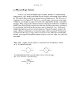
2.1.5 Ladder Logic Outputs
In ladder logic there are multiple types of outputs, but these are not consistently
available on all PLCs. Some of the outputs will be externally connected to devices outside
the PLC, but it is also possible to use internal memory locations in the PLC. Six types of
outputs are shown in Figure 2.12. The first is a normal output, when energized the output
will turn on, and energize an output. The circle with a diagonal line through is a normally
on output. When energized the output will turn off. This type of output is not available on
all PLC types. When initially energized the OSR (One Shot Relay) instruction will turn on
for one scan, but then be off for all scans after, until it is turned off. The L (latch) and U
(unlatch) instructions can be used to lock outputs on. When an L output is energized the
output will turn on indefinitely, even when the output coil is deenergized. The output can
only be turned off using a U output. The last instruction is the IOT (Immediate OutpuT)
that will allow outputs to be updated without having to wait for the ladder logic scan to be
completed.
When power is applied (on) the output x is activated for the left output, but turned
An input transition on will cause the output x to go on for one scan
xx
OSR
x
(this is also known as a one shot relay)
off for the output on the right.
plc wiring - 2.13
Figure 2.12 Ladder Logic Outputs
2.2 A CASE STUDY
Problem: Try to develop (without looking at the solution) a relay based controller
that will allow three switches in a room to control a single light.
When the L coil is energized, x will be toggled on, it will stay on until the U coil
Some PLCs will allow immediate outputs that do not wait for the program scan to
L
U
IOT
end before setting an output. (Note: This instruction will only update the outputs using
is energized. This is like a flip-flop and stays set even when the PLC is turned off.
x
xx
the output table, other instruction must change the individual outputs.)
Note: Outputs are also commonly shown using parentheses -( )- instead of
the circle. This is because many of the programming systems are text
based and circles cannot be drawn.
plc wiring - 2.14
2.3 SUMMARY
• Normally open and closed contacts.
• Relays and their relationship to ladder logic.
• PLC outputs can be inputs, as shown by the seal in circuit.
• Programming can be done with ladder logic, mnemonics, SFCs, and structured
text.
• There are multiple ways to write a PLC program.
Solution: There are two possible approaches to this problem. The first assumes that any
one of the switches on will turn on the light, but all three switches must be off for the
light to be off.
switch 1
switch 2
switch 3
light
The second solution assumes that each switch can turn the light on or off, regardless of
the states of the other switches. This method is more complex and involves thinking
through all of the possible combinations of switch positions. You might recognize
this problem as an exclusive or problem.
switch 1
switch 1
switch 1
light
switch 2
switch 2
switch 2
switch 3
switch 3
switch 3
switch 1 switch 2 switch 3
Note: It is important to get a clear understanding of how the controls are expected to
work. In this example two radically different solutions were obtained based upon a
simple difference in the operation.
plc wiring - 2.15
2.4 PRACTICE PROBLEMS
1. Give an example of where a PLC could be used.
2. Why would relays be used in place of PLCs?
3. Give a concise description of a PLC.
4. List the advantages of a PLC over relays.
5. A PLC can effectively replace a number of components. Give examples and discuss some good
and bad applications of PLCs.
6. Explain the trade-offs between relays and PLCs for control applications.
7. Explain why ladder logic outputs are coils?
8. In the figure below, will the power for the output on the first rung normally be on or off? Would
the output on the second rung normally be on or off?
9. Write the mnemonic program for the Ladder Logic below.
2.5 PRACTICE PROBLEM SOLUTIONS
1. to control a conveyor system
2. for simple designs
3. A PLC is a computer based controller that uses inputs to monitor a process, and uses outputs to
100
101
201
plc wiring - 2.16
control a process. A simple program is used to set the controller behavior.
4. less expensive for complex processes, debugging tools, reliable, flexible, easy to expend, etc.
5. A PLC could replace a few relays. In this case the relays might be easier to install and less
expensive. To control a more complex system the controller might need timing, counting and
other mathematical calculations. In this case a PLC would be a better choice.
6. trade-offs include: cost, complexity, easy of debugging, etc.
7. the ladder logic outputs were modelled on relay logic diagrams. The output in a relay ladder
diagram is a relay coil. This is normally drawn as a circle.
8. off, on
9. LD 100, LD 101, OR, ST 201
2.6 ASSIGNMENT PROBLEMS
1. Develop a simple ladder logic program that will turn on an output X if inputs A and B, or input
C is on.
plc wiring - 3.1
3. PLC HARDWARE
3.1 INTRODUCTION
Many PLC configurations are available, even from a single vendor. But, in each of
these there are common components and concepts. The most essential components are:
Power Supply - This can be built into the PLC or be an external unit. Common
voltage levels required by the PLC (with and without the power supply) are
24Vdc, 120Vac, 220Vac.
CPU (Central Processing Unit) - This is a computer where ladder logic is stored
and processed.
I/O (Input/Output) - A number of input/output terminals must be provided so that
the PLC can monitor the process and initiate actions.
Indicator lights - These indicate the status of the PLC including power on, program
running, and a fault. These are essential when diagnosing problems.
The configuration of the PLC refers to the packaging of the components. Typical
configurations are listed below from largest to smallest as shown in Figure 3.1.
Rack - A rack is often large (up to 18” by 30” by 10”) and can hold multiple cards.
When necessary, multiple racks can be connected together. These tend to be the
highest cost, but also the most flexible and easy to maintain.
Mini - These are similar in function to PLC racks, but about half the size.
Shoebox - A compact, all-in-one unit (about the size of a shoebox) that has limited
expansion capabilities. Lower cost, and compactness make these ideal for small
applications.
Micro - These units can be as small as a deck of cards. They tend to have fixed
Topics:
Objectives:
• Be able to understand and design basic input and output wiring.
• Be able to produce industrial wiring diagrams.
• PLC hardware configurations
• Input and outputs types
• Electrical wiring for inputs and outputs
• Relays
• Electrical Ladder Diagrams and JIC wiring symbols
plc wiring - 3.2
quantities of I/O and limited abilities, but costs will be the lowest.
Software - A software based PLC requires a computer with an interface card, but
allows the PLC to be connected to sensors and other PLCs across a network.
Figure 3.1 Typical Configurations for PLC
3.2 INPUTS AND OUTPUTS
Inputs to, and outputs from, a PLC are necessary to monitor and control a process.
Both inputs and outputs can be categorized into two basic types: logical or continuous.
Consider the example of a light bulb. If it can only be turned on or off, it is logical control.
If the light can be dimmed to different levels, it is continuous. Continuous values seem
more intuitive, but logical values are preferred because they allow more certainty, and
simplify control. As a result most controls applications (and PLCs) use logical inputs and
outputs for most applications. Hence, we will discuss logical I/O and leave continuous I/O
for later.
Outputs to actuators allow a PLC to cause something to happen in a process. A
short list of popular actuators is given below in order of relative popularity.
Solenoid Valves - logical outputs that can switch a hydraulic or pneumatic flow.
Lights - logical outputs that can often be powered directly from PLC output
boards.
Motor Starters - motors often draw a large amount of current when started, so they
require motor starters, which are basically large relays.
Servo Motors - a continuous output from the PLC can command a variable speed
or position.
rack
mini
micro
plc wiring - 3.3
Outputs from PLCs are often relays, but they can also be solid state electronics
such as transistors for DC outputs or Triacs for AC outputs. Continuous outputs require
special output cards with digital to analog converters.
Inputs come from sensors that translate physical phenomena into electrical signals.
Typical examples of sensors are listed below in relative order of popularity.
Proximity Switches - use inductance, capacitance or light to detect an object logi-
cally.
Switches - mechanical mechanisms will open or close electrical contacts for a log-
ical signal.
Potentiometer - measures angular positions continuously, using resistance.
LVDT (linear variable differential transformer) - measures linear displacement
continuously using magnetic coupling.
Inputs for a PLC come in a few basic varieties, the simplest are AC and DC inputs.
Sourcing and sinking inputs are also popular. This output method dictates that a device
does not supply any power. Instead, the device only switches current on or off, like a sim-
ple switch.
Sinking - When active the output allows current to flow to a common ground. This
is best selected when different voltages are supplied.
Sourcing - When active, current flows from a supply, through the output device
and to ground. This method is best used when all devices use a single supply
voltage.
This is also referred to as NPN (sinking) and PNP (sourcing). PNP is more popu-
lar. This will be covered in more detail in the chapter on sensors.
3.2.1 Inputs
In smaller PLCs the inputs are normally built in and are specified when purchasing
the PLC. For larger PLCs the inputs are purchased as modules, or cards, with 8 or 16
inputs of the same type on each card. For discussion purposes we will discuss all inputs as
if they have been purchased as cards. The list below shows typical ranges for input volt-
ages, and is roughly in order of popularity.
12-24 Vdc
100-120 Vac
10-60 Vdc
12-24 Vac/dc
plc wiring - 3.4
5 Vdc (TTL)
200-240 Vac
48 Vdc
24 Vac
PLC input cards rarely supply power, this means that an external power supply is
needed to supply power for the inputs and sensors. The example in Figure 3.2 shows how
to connect an AC input card.
Figure 3.2 An AC Input Card and Ladder Logic
24 V AC
Power
Supply
normally open push-button
normally open
temperature switch
PLC Input Card
24V AC
it is in rack 1
I/O Group 3
00
01
02
03
04
05
06
07
I:013
01
I:013
03
Push Button
Temperature Sensor
COM
Note: inputs are normally high impedance. This means that they will
use very little current.
Hot
Neut.
plc wiring - 3.5
In the example there are two inputs, one is a normally open push button, and the
second is a temperature switch, or thermal relay. (NOTE: These symbols are standard and
will be discussed in chapter 24.) Both of the switches are powered by the hot output of the
24Vac power supply - this is like the positive terminal on a DC supply. Power is supplied
to the left side of both of the switches. When the switches are open there is no voltage
passed to the input card. If either of the switches are closed power will be supplied to the
input card. In this case inputs 1 and 3 are used - notice that the inputs start at 0. The input
card compares these voltages to the common. If the input voltage is within a given toler-
ance range the inputs will switch on. Ladder logic is shown in the figure for the inputs.
Here it uses Allen Bradley notation for PLC-5 racks. At the top is the location of the input
card I:013 which indicates that the card is an Input card in rack 01 in slot 3. The input
number on the card is shown below the contact as 01 and 03.
Many beginners become confused about where connections are needed in the cir-
cuit above. The key word to remember is circuit, which means that there is a full loop that
the voltage must be able to follow. In Figure 3.2 we can start following the circuit (loop) at
the power supply. The path goes through the switches, through the input card, and back to
the power supply where it flows back through to the start. In a full PLC implementation
there will be many circuits that must each be complete.
A second important concept is the common. Here the neutral on the power supply
is the common, or reference voltage. In effect we have chosen this to be our 0V reference,
and all other voltages are measured relative to it. If we had a second power supply, we
would also need to connect the neutral so that both neutrals would be connected to the
same common. Often common and ground will be confused. The common is a reference,
or datum voltage that is used for 0V, but the ground is used to prevent shocks and damage
to equipment. The ground is connected under a building to a metal pipe or grid in the
ground. This is connected to the electrical system of a building, to the power outlets,
where the metal cases of electrical equipment are connected. When power flows through
the ground it is bad. Unfortunately many engineers, and manufacturers mix up ground and
common. It is very common to find a power supply with the ground and common misla-
beled.
One final concept that tends to trap beginners is that each input card is isolated.
This means that if you have connected a common to only one card, then the other cards are
not connected. When this happens the other cards will not work properly. You must con-
nect a common for each of the output cards.
Remember - Don’t mix up the ground and common. Don’t connect them together if the
common of your device is connected to a common on another device.
plc wiring - 3.6
There are many trade-offs when deciding which type of input cards to use.
• DC voltages are usually lower, and therefore safer (i.e., 12-24V).
• DC inputs are very fast, AC inputs require a longer on-time. For example, a 60Hz
wave may require up to 1/60sec for reasonable recognition.
• DC voltages can be connected to larger variety of electrical systems.
• AC signals are more immune to noise than DC, so they are suited to long dis-
tances, and noisy (magnetic) environments.
• AC power is easier and less expensive to supply to equipment.
• AC signals are very common in many existing automation devices.
Figure 3.3 Aside: PLC Input Circuits
ASIDE: PLC inputs must convert a variety of logic levels to the 5Vdc logic levels
used on the data bus. This can be done with circuits similar to those shown below.
Basically the circuits condition the input to drive an optocoupler. This electrically
isolates the external electrical circuitry from the internal circuitry. Other circuit
components are used to guard against excess or reversed voltage polarity.
TTL
+5V
optocoupler
TTL
+5V
optocoupler
DC
input
AC
input
+
COM
hot
neut.
plc wiring - 3.7
3.2.2 Output Modules
As with input modules, output modules rarely supply any power, but instead act as
switches. External power supplies are connected to the output card and the card will
switch the power on or off for each output. Typical output voltages are listed below, and
roughly ordered by popularity.
120 Vac
24 Vdc
12-48 Vac
12-48 Vdc
5Vdc (TTL)
230 Vac
These cards typically have 8 to 16 outputs of the same type and can be purchased
with different current ratings. A common choice when purchasing output cards is relays,
transistors or triacs. Relays are the most flexible output devices. They are capable of
switching both AC and DC outputs. But, they are slower (about 10ms switching is typi-
cal), they are bulkier, they cost more, and they will wear out after millions of cycles. Relay
outputs are often called dry contacts. Transistors are limited to DC outputs, and Triacs are
limited to AC outputs. Transistor and triac outputs are called switched outputs.
- Dry contacts - a separate relay is dedicated to each output. This allows mixed
voltages (AC or DC and voltage levels up to the maximum), as well as isolated
outputs to protect other outputs and the PLC. Response times are often greater
than 10ms. This method is the least sensitive to voltage variations and spikes.
- Switched outputs - a voltage is supplied to the PLC card, and the card switches it
to different outputs using solid state circuitry (transistors, triacs, etc.) Triacs are
well suited to AC devices requiring less than 1A. Transistor outputs use NPN or
PNP transistors up to 1A typically. Their response time is well under 1ms.
WARNING - ALWAYS CHECK RATED VOLTAGES AND CURRENTS FOR PLC’s
AND NEVER EXCEED!
plc wiring - 3.8
Figure 3.4 Aside: PLC Output Circuits
Caution is required when building a system with both AC and DC outputs. If AC is
ASIDE: PLC outputs must convert the 5Vdc logic levels on the PLC data bus to exter-
nal voltage levels. This can be done with circuits similar to those shown below.
Basically the circuits use an optocoupler to switch external circuitry. This electri-
cally isolates the external electrical circuitry from the internal circuitry. Other cir-
cuit components are used to guard against excess or reversed voltage polarity.
TTL
+V
optocoupler
Sourcing DC output
TTL
optocoupler
AC
output
TTL
+V
relay
output
AC/DC
Note: Some AC outputs will
also use zero voltage detec-
tion. This allows the output
to be switched on when the
voltage and current are
effectively off, thus prevent-
ing surges.
plc wiring - 3.9
accidentally connected to a DC transistor output it will only be on for the positive half of
the cycle, and appear to be working with a diminished voltage. If DC is connected to an
AC triac output it will turn on and appear to work, but you will not be able to turn it off
without turning off the entire PLC.
A major issue with outputs is mixed power sources. It is good practice to isolate all
power supplies and keep their commons separate, but this is not always feasible. Some
output modules, such as relays, allow each output to have its own common. Other output
cards require that multiple, or all, outputs on each card share the same common. Each out-
put card will be isolated from the rest, so each common will have to be connected. It is
common for beginners to only connect the common to one card, and forget the other cards
- then only one card seems to work!
The output card shown in Figure 3.5 is an example of a 24Vdc output card that has
a shared common. This type of output card would typically use transistors for the outputs.
ASIDE: A transistor is a semiconductor based device that can act as an adjustable valve.
When switched off it will block current flow in both directions. While switched on it
will allow current flow in one direction only. There is normally a loss of a couple of
volts across the transistor. A triac is like two transistors connected together so that
current can flow in both directions, which is good for AC current. One major differ-
ence for a triac is that if it has been switched on so that current flows, and then
switched off, it will not turn off until the current stops flowing. This is fine with AC
current because the current stops and reverses every 1/2 cycle, but this does not hap-
pen with DC current, and so the triac will remain on.
plc wiring - 3.10
Figure 3.5 An Example of a 24Vdc Output Card (Sinking)
In this example the outputs are connected to a low current light bulb (lamp) and a
relay coil. Consider the circuit through the lamp, starting at the 24Vdc supply. When the
output 07 is on, current can flow in 07 to the COM, thus completing the circuit, and allow-
ing the light to turn on. If the output is off the current cannot flow, and the light will not
turn on. The output 03 for the relay is connected in a similar way. When the output 03 is
on, current will flow through the relay coil to close the contacts and supply 120Vac to the
motor. Ladder logic for the outputs is shown in the bottom right of the figure. The notation
is for an Allen Bradley PLC-5. The value at the top left of the outputs, O:012, indicates
that the card is an output card, in rack 01, in slot 2 of the rack. To the bottom right of the
outputs is the output number on the card 03 or 07. This card could have many different
24 V DC
Output Card
in rack 01
I/O group 2
COM
00
01
02
03
04
05
06
07
24 V Lamp
Relay
+24 V DC
Power
120 V AC
Power
Motor
Supply
Supply
O:012
03
O:012
07
Motor
Lamp
Neut.
COM
plc wiring - 3.11
voltages applied from different sources, but all the power supplies would need a single
shared common.
The circuits in Figure 3.6 had the sequence of power supply, then device, then PLC
card, then power supply. This requires that the output card have a common. Some output
schemes reverse the device and PLC card, thereby replacing the common with a voltage
input. The example in Figure 3.5 is repeated in Figure 3.6 for a voltage supply card.
Figure 3.6 An Example of a 24Vdc Output Card With a Voltage Input (Sourcing)
In this example the positive terminal of the 24Vdc supply is connected to the out-
24 V DC
Output Card
in rack 01
I/O group 2
V+
00
01
02
03
04
05
06
07
24 V lamp
Relay
+24 V DC
Power
120 V AC
Power
Motor
Supply
Supply
O:012
03
O:012
07
Motor
Lamp
Neut.
COM
plc wiring - 3.12
put card directly. When an output is on power will be supplied to that output. For example,
if output 07 is on then the supply voltage will be output to the lamp. Current will flow
through the lamp and back to the common on the power supply. The operation is very sim-
ilar for the relay switching the motor. Notice that the ladder logic (shown in the bottom
right of the figure) is identical to that in Figure 3.5. With this type of output card only one
power supply can be used.
We can also use relay outputs to switch the outputs. The example shown in Figure
3.5 and Figure 3.6 is repeated yet again in Figure 3.7 for relay output.
Figure 3.7 An Example of a Relay Output Card
120 V AC/DC
Output Card
in rack 01
I/O group 2
00
01
02
03
04
05
06
07
24 V lamp
Relay
24 V DC
Power
120 V AC
Power
Motor
Supply
Supply
O:012
03
O:012
07
Motor
Lamp
plc wiring - 3.13
In this example the 24Vdc supply is connected directly to both relays (note that
this requires 2 connections now, whereas the previous example only required one.) When
an output is activated the output switches on and power is delivered to the output devices.
This layout is more similar to Figure 3.6 with the outputs supplying voltage, but the relays
could also be used to connect outputs to grounds, as in Figure 3.5. When using relay out-
puts it is possible to have each output isolated from the next. A relay output card could
have AC and DC outputs beside each other.
3.3 RELAYS
Although relays are rarely used for control logic, they are still essential for switch-
ing large power loads. Some important terminology for relays is given below.
Contactor - Special relays for switching large current loads.
Motor Starter - Basically a contactor in series with an overload relay to cut off
when too much current is drawn.
Arc Suppression - when any relay is opened or closed an arc will jump. This
becomes a major problem with large relays. On relays switching AC this prob-
lem can be overcome by opening the relay when the voltage goes to zero (while
crossing between negative and positive). When switching DC loads this prob-
lem can be minimized by blowing pressurized gas across during opening to sup-
press the arc formation.
AC coils - If a normal relay coil is driven by AC power the contacts will vibrate
open and closed at the frequency of the AC power. This problem is overcome
by adding a shading pole to the relay.
The most important consideration when selecting relays, or relay outputs on a
PLC, is the rated current and voltage. If the rated voltage is exceeded, the contacts will
wear out prematurely, or if the voltage is too high fire is possible. The rated current is the
maximum current that should be used. When this is exceeded the device will become too
hot, and it will fail sooner. The rated values are typically given for both AC and DC,
although DC ratings are lower than AC. If the actual loads used are below the rated values
the relays should work well indefinitely. If the values are exceeded a small amount the life
of the relay will be shortened accordingly. Exceeding the values significantly may lead to
immediate failure and permanent damage.
• Rated Voltage - The suggested operation voltage for the coil. Lower levels can
result in failure to operate, voltages above shorten life.
• Rated Current - The maximum current before contact damage occurs (welding or
melting).
plc wiring - 3.14
3.4 A CASE STUDY
(Try the following case without looking at the solution in Figure 3.8.) An electrical
layout is needed for a hydraulic press. The press uses a 24Vdc double actuated solenoid
valve to advance and retract the press. This device has a single common and two input
wires. Putting 24Vdc on one wire will cause the press to advance, putting 24Vdc on the
second wire will cause it to retract. The press is driven by a large hydraulic pump that
requires 220Vac rated at 20A, this should be running as long as the press is on. The press
is outfitted with three push buttons, one is a NC stop button, the other is a NO manual
retract button, and the third is a NO start automatic cycle button. There are limit switches
at the top and bottom of the press travels that must also be connected.
Figure 3.8 Case Study for Press Wiring
The input and output cards were both selected to be 24Vdc so that they may share
a single 24Vdc power supply. In this case the solenoid valve was wired directly to the out-
put card, while the hydraulic pump was connected indirectly using a relay (only the coil is
shown for simplicity). This decision was primarily made because the hydraulic pump
24VDC
24VDC
advance
retract
solenoid
com
24VDC
+
-
O/0
O/1
O/2
I/0
I/1
I/2
I/3
I/4
com
SOLUTION
relay for
hydraulic pump
output card
input card
plc wiring - 3.15
requires more current than any PLC can handle, but a relay would be relatively easy to
purchase and install for that load. All of the input switches are connected to the same sup-
ply and to the inputs.
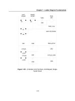
3.5 ELECTRICAL WIRING DIAGRAMS
When a controls cabinet is designed and constructed ladder diagrams are used to
document the wiring. A basic wiring diagram is shown in Figure 3.9. In this example the
system would be supplied with AC power (120Vac or 220Vac) on the left and right rails.
The lines of these diagrams are numbered, and these numbers are typically used to number
wires when building the electrical system. The switch before line 010 is a master discon-
nect for the power to the entire system. A fuse is used after the disconnect to limit the
maximum current drawn by the system. Line 020 of the diagram is used to control power
to the outputs of the system. The stop button is normally closed, while the start button is
normally open. The branch, and output of the rung are CR1, which is a master control
relay. The PLC receives power on line 30 of the diagram.
The inputs to the PLC are all AC, and are shown on lines 040 to 070. Notice that
Input I:0/0 is a set of contacts on the MCR CR1. The three other inputs are a normally
open push button (050), a limit switch (060) and a normally closed push button (070).
After line 080 the MCR CR1 can apply power to the outputs. These power the relay out-
puts of the PLC to control a red indicator light (040), a green indicator light (050), a sole-
noid (060), and another relay (080). The relay on line 080 switches a relay that turn on
another device drill station.