Học lập trình Vi Xử lý băng ngôn ngữ C - P2
Bạn đang xem bản rút gọn của tài liệu. Xem và tải ngay bản đầy đủ của tài liệu tại đây (2.38 MB, 175 trang )
I
Programming
Embedded
Systems II
A 10-week course, using C
40
39
38
37
36
35
34
1
2
3
4
5
6
7
‘8051’
8
9
10
33
32
31
30
29
28
27
26
25
24
11
12
13
14
15
16
17
18
19
20
23
22
21
P3.0
P1.7
RST
P1.6
P1.5
P1.4
P1.2
P1.3
P1.1
P1.0
VSS
XTL2
XTL1
P3.7
P3.6
P3.5
P3.3
P3.4
P3.2
P3.1
/ EA
P0.6
P0.7
P0.5
P0.4
P0.3
P0.1
P0.2
P0.0
VCC
P2.0
P2.2
P2.1
P2.3
P2.4
P2.5
P2.7
P2.6
/ PSEN
ALE
Michael J. Pont
University of Leicester
[v1.1]
II
Copyright © Michael J. Pont, 2002-2003
This document may be freely distributed and copied, provided that copyright notice at
the foot of each OHP page is clearly visible in all copies.
III
Seminar 1: A flexible scheduler for single-processor embedded systems 1
Overview of this seminar 2
Overview of this course 3
By the end of the course you’ll be able to … 4
Main course text 5
IMPORTANT: Course prerequisites 6
Review: Why use C? 7
Review: The 8051 microcontroller 8
Review: The “super loop” software architecture 9
Review: An introduction to schedulers 10
Review: Building a scheduler 11
Overview of this seminar 12
The Co-operative Scheduler 13
Overview 14
The scheduler data structure and task array 15
The size of the task array 16
One possible initialisation function: 17
IMPORTANT: The ‘one interrupt per microcontroller’ rule! 18
The ‘Update’ function 19
The ‘Add Task’ function 20
The ‘Dispatcher’ 22
Function arguments 24
Function pointers and Keil linker options 25
The ‘Start’ function 28
The ‘Delete Task’ function 29
Reducing power consumption 30
Reporting errors 31
Displaying error codes 34
Hardware resource implications 35
What is the CPU load of the scheduler? 36
Determining the required tick interval 38
Guidelines for predictable and reliable scheduling 40
Overall strengths and weaknesses of the scheduler 41
Preparations for the next seminar 42
IV
Seminar 2: A closer look at co-operative task scheduling (and some alternatives) 43
Overview of this seminar 44
Review: Co-operative scheduling 45
The pre-emptive scheduler 46
Why do we avoid pre-emptive schedulers in this course? 47
Why is a co-operative scheduler (generally) more reliable? 48
Critical sections of code 49
How do we deal with critical sections in a pre-emptive system? 50
Building a “lock” mechanism 51
The “best of both worlds” - a hybrid scheduler 55
Creating a hybrid scheduler 56
The ‘Update’ function for a hybrid scheduler. 58
Reliability and safety issues 61
The safest way to use the hybrid scheduler 63
Other forms of co-operative scheduler 65
PATTERN: 255-TICK SCHEDULER 66
PATTERN: ONE-TASK SCHEDULER 67
PATTERN: ONE-YEAR SCHEDULER 68
PATTERN: STABLE SCHEDULER 69
Mix and match … 70
Preparations for the next seminar 71
V
Seminar 3: Shared-clock schedulers for multi-processor systems 73
Overview of this seminar 74
Why use more than one processor? 75
Additional CPU performance and hardware facilities 76
The benefits of modular design 78
The benefits of modular design 79
So - how do we link more than one processor? 80
Synchronising the clocks 81
Synchronising the clocks 82
Synchronising the clocks - Slave nodes 83
Transferring data 84
Transferring data (Master to Slave) 85
Transferring data (Slave to Master) 86
Transferring data (Slave to Master) 87
Detecting network and node errors 88
Detecting errors in the Slave(s) 89
Detecting errors in the Master 90
Handling errors detected by the Slave 91
Handling errors detected by the Master 92
Enter a safe state and shut down the network 93
Reset the network 94
Engage a backup Slave 95
Why additional processors may not improve reliability 96
Redundant networks do not guarantee increased reliability 97
Replacing the human operator - implications 98
Are multi-processor designs ever safe? 99
Preparations for the next seminar 100
VI
Seminar 4: Linking processors using RS-232 and RS-485 protocols 101
Review: Shared-clock scheduling 102
Overview of this seminar 103
Review: What is ‘RS-232’? 104
Review: Basic RS-232 Protocol 105
Review: Transferring data to a PC using RS-232 106
PATTERN: SCU SCHEDULER (LOCAL) 107
The message structure 108
Determining the required baud rate 111
Node Hardware 113
Network wiring 114
Overall strengths and weaknesses 115
PATTERN: SCU Scheduler (RS-232) 116
PATTERN: SCU Scheduler (RS-485) 117
RS-232 vs RS-485 [number of nodes] 118
RS-232 vs RS-485 [range and baud rates] 119
RS-232 vs RS-485 [cabling] 120
RS-232 vs RS-485 [transceivers] 121
Software considerations: enable inputs 122
Overall strengths and weaknesses 123
Example: Network with Max489 transceivers 124
Preparations for the next seminar 125
VII
Seminar 5: Linking processors using the Controller Area Network (CAN) bus 127
Overview of this seminar 128
PATTERN: SCC Scheduler 129
What is CAN? 130
CAN 1.0 vs. CAN 2.0 132
Basic CAN vs. Full CAN 133
Which microcontrollers have support for CAN? 134
S-C scheduling over CAN 135
The message structure - Tick messages 136
The message structure - Ack messages 137
Determining the required baud rate 138
Transceivers for distributed networks 140
Node wiring for distributed networks 141
Hardware and wiring for local networks 142
Software for the shared-clock CAN scheduler 143
Overall strengths and weaknesses 144
Example: Creating a CAN-based scheduler using the Infineon C515c 145
Master Software 146
Slave Software 159
What about CAN without on-chip hardware support? 166
Preparations for the next seminar 168
VIII
Seminar 6: Case study: Intruder alarm system using CAN 169
Overview of this seminar 170
Overview of the required system 171
System Operation 172
How many processors? 173
The Controller node 174
Patterns for the Controller node 175
The Sensor / Sounder node 176
Patterns for the Sensor / Sounder node 177
Meeting legal requirements 178
Processor decisions 179
Hardware foundation 181
Summary 182
The code: Controller node (List of files) 183
The code: Controller node (Main.c) 184
The code: Controller node (Intruder.c) 185
The code: Controller node (Sounder.c) 197
The code: Controller node (SCC_m89S53.c) 198
The code: Sensor / Sounder node (List of files) 212
The code: Sensor / Sounder node (Main.c) 213
The code: Sensor / Sounder node (Intruder.c) 214
The code: Sensor / Sounder node (Sounder.c) 216
The code: Sensor / Sounder node (SCC_s89S53.c) 218
Preparations for the next seminar 228
IX
Seminar 7: Processing sequences of analogue values 229
Overview of this seminar 230
PATTERN: One-Shot ADC 231
Using a microcontroller with on-chip ADC 232
Using an external parallel ADC 233
Example: Using a Max150 ADC 234
Using an external serial ADC 235
Example: Using an external SPI ADC 236
Example: Using an external I
2
C ADC 237
Using a current-mode ADC? 238
PATTERN: SEQUENTIAL ADC 239
Key design stages 241
Sample rate (monitoring and signal proc. apps) 242
Sample rate (control systems) 243
Determining the required bit rate 244
Impact on the software architecture 245
Example: Using the c515c internal ADC 247
PATTERN: ADC PRE-AMP 248
PATTERN: A-A FILTER 249
Example: Speech-recognition system 250
Alternative: “Over sampling” 251
PATTERN: CURRENT SENSOR 252
PWM revisited 253
Software PWM 254
Using Digital-to-Analogue Converters (DACs) 255
Decisions … 256
General implications for the software architecture 257
Example: Speech playback using a 12-bit parallel DAC 258
Example: Digital telephone system 260
Preparations for the next seminar 261
X
Seminar 8: Applying “Proportional Integral Differential” (PID) control 263
Overview of this seminar 264
Why do we need closed-loop control? 265
Closed-loop control 269
What closed-loop algorithm should you use? 270
What is PID control? 271
A complete PID control implementation 272
Another version 273
Dealing with ‘windup’ 274
Choosing the controller parameters 275
What sample rate? 276
Hardware resource implications 277
PID: Overall strengths and weaknesses 278
Why open-loop controllers are still (sometimes) useful 279
Limitations of PID control 280
Example: Tuning the parameters of a cruise-control system 281
Open-loop test 283
Tuning the PID parameters: methodology 284
First test 285
Example: DC Motor Speed Control 287
Alternative: Fuzzy control 290
Preparations for the next seminar 291
XI
Seminar 9: Case study: Automotive cruise control using PID and CAN 293
Overview of this seminar 294
Single-processor system: Overview 295
Single-processor system: Code 296
Multi-processor design: Overview 297
Multi-processor design: Code (PID node) 298
Multi-processor design: Code (Speed node) 299
Multi-processor design: Code (Throttle node) 300
Exploring the impact of network delays 301
Example: Impact of network delays on the CCS system 302
Preparations for the next seminar 303
XII
Seminar 10: Improving system reliability using watchdog timers 305
Overview of this seminar 306
The watchdog analogy 307
PATTERN: Watchdog Recovery 308
Choice of hardware 309
Time-based error detection 310
Other uses for watchdog-induced resets 311
Recovery behaviour 312
Risk assessment 313
The limitations of single-processor designs 314
Time, time, time … 315
Watchdogs: Overall strengths and weaknesses 316
PATTERN: Scheduler Watchdog 317
Selecting the overflow period - “hard” constraints 318
Selecting the overflow period - “soft” constraints 319
PATTERN: Program-Flow Watchdog 320
Dealing with errors 322
Hardware resource implications 323
Speeding up the response 324
PATTERN: Reset Recovery 326
PATTERN: Fail-Silent Recovery 327
Example: Fail-Silent behaviour in the Airbus A310 328
Example: Fail-Silent behaviour in a steer-by-wire application 329
PATTERN: Limp-Home Recovery 330
Example: Limp-home behaviour in a steer-by-wire application 331
PATTERN: Oscillator Watchdog 334
Conclusions 336
Acknowledgements 337
COPYRIGHT © MICHAEL J. PONT, 2001-2003. Contains material from:
Pont, M.J. (2001) “Patterns for triggered embedded systems”, Addison-Wesley.
PES II - 1
Seminar 1:
A flexible scheduler
for single-processor
embedded systems
40
39
38
37
36
35
34
1
2
3
4
5
6
7
‘8051’
8
9
10
33
32
31
30
29
28
27
26
25
24
11
12
13
14
15
16
17
18
19
20
23
22
21
P3.0
P1.7
RST
P1.6
P1.5
P1.4
P1.2
P1.3
P1.1
P1.0
VSS
XTL2
XTL1
P3.7
P3.6
P3.5
P3.3
P3.4
P3.2
P3.1
/ EA
P0.6
P0.7
P0.5
P0.4
P0.3
P0.1
P0.2
P0.0
VCC
P2.0
P2.2
P2.1
P2.3
P2.4
P2.5
P2.7
P2.6
/ PSEN
ALE
COPYRIGHT © MICHAEL J. PONT, 2001-2003. Contains material from:
Pont, M.J. (2001) “Patterns for triggered embedded systems”, Addison-Wesley.
PES II - 2
Overview of this seminar
This introductory seminar will:
• Provide an overview of this course
• Describe the design and implementation of a flexible
scheduler
COPYRIGHT © MICHAEL J. PONT, 2001-2003. Contains material from:
Pont, M.J. (2001) “Patterns for triggered embedded systems”, Addison-Wesley.
PES II - 3
Overview of this course
This course is primarily concerned with the implementation of
software (and a small amount of hardware) for embedded systems
constructed using more than one microcontroller.
The processors examined in detail will be from the 8051 family.
All programming will be in the ‘C’ language
(using the Keil C51 compiler)
COPYRIGHT © MICHAEL J. PONT, 2001-2003. Contains material from:
Pont, M.J. (2001) “Patterns for triggered embedded systems”, Addison-Wesley.
PES II - 4
By the end of the course you’ll be able to …
By the end of the course, you will be able to:
1. Design software for multi-processor embedded applications
based on small, industry standard, microcontrollers;
2. Implement the above designs using a modern, high-level
programming language (‘C’), and
3. Understand more about the effect that software design and
programming designs can have on the reliability and safety
of multi-processor embedded systems.
COPYRIGHT © MICHAEL J. PONT, 2001-2003. Contains material from:
Pont, M.J. (2001) “Patterns for triggered embedded systems”, Addison-Wesley.
PES II - 5
Main course text
Throughout this course, we will be making heavy use of this book:
Patterns for time-triggered embedded
systems: Building reliable applications with
the 8051 family of microcontrollers,
by Michael J. Pont (2001)
Addison-Wesley / ACM Press.
[ISBN: 0-201-331381]
For further details, please see:
/>COPYRIGHT © MICHAEL J. PONT, 2001-2003. Contains material from:
Pont, M.J. (2001) “Patterns for triggered embedded systems”, Addison-Wesley.
PES II - 6
IMPORTANT: Course prerequisites
• It is assumed that - before taking this course - you have
previously completed “Programming Embedded Systems I”
(or a similar course).
See:
www.le.ac.uk/engineering/mjp9/pttesguide.htm
B
E
C
5.5V, 0.3A lamp
ZTX751
4V - 6V (battery)
10 KΩ
10 µF
4 MHz
20
19
18
17
16
15
14
1
2
3
4
5
6
7
Atmel 2051
8
9
10
13
12
11
GND
P3.4
P3.5
P3.3
P3.2
XTL1
P3.1
XTL2
P3.0
RST
P3.7
P1.1
P1.0
P1.2
P1.3
P1.4
P1.6
P1.5
P1.7
VCC
40
39
38
37
36
35
34
1
2
3
4
5
6
7
‘8051’
8
9
10
33
32
31
30
29
28
27
26
25
24
11
12
13
14
15
16
17
18
19
20
23
22
21
P3.0
P1.7
RST
P1.6
P1.5
P1.4
P1.2
P1.3
P1.1
P1.0
VSS
XTL2
XTL1
P3.7
P3.6
P3.5
P3.3
P3.4
P3.2
P3.1
/ EA
P0.6
P0.7
P0.5
P0.4
P0.3
P0.1
P0.2
P0.0
VCC
P2.0
P2.2
P2.1
P2.3
P2.4
P2.5
P2.7
P2.6
/ PSEN
ALE
COPYRIGHT © MICHAEL J. PONT, 2001-2003. Contains material from:
Pont, M.J. (2001) “Patterns for triggered embedded systems”, Addison-Wesley.
PES II - 7
Review: Why use C?
• It is a ‘mid-level’ language, with ‘high-level’ features (such
as support for functions and modules), and ‘low-level’
features (such as good access to hardware via pointers);
• It is very efficient;
• It is popular and well understood;
• Even desktop developers who have used only Java or C++
can soon understand C syntax;
• Good, well-proven compilers are available for every
embedded processor (8-bit to 32-bit or more);
• Experienced staff are available;
• Books, training courses, code samples and WWW sites
discussing the use of the language are all widely available.
Overall, C may not be an ideal language for developing embedded
systems, but it is a good choice (and is unlikely that a ‘perfect’ language
will ever be created).
COPYRIGHT © MICHAEL J. PONT, 2001-2003. Contains material from:
Pont, M.J. (2001) “Patterns for triggered embedded systems”, Addison-Wesley.
PES II - 8
Review: The 8051 microcontroller
40
39
38
37
36
35
34
1
2
3
4
5
6
7
‘8051’
8
9
10
33
32
31
30
29
28
27
26
25
24
11
12
13
14
15
16
17
18
19
20
23
22
21
P3.0
P1.7
RST
P1.6
P1.5
P1.4
P1.2
P1.3
P1.1
P1.0
VSS
XTL2
XTL1
P3.7
P3.6
P3.5
P3.3
P3.4
P3.2
P3.1
/ EA
P0.6
P0.7
P0.5
P0.4
P0.3
P0.1
P0.2
P0.0
VCC
P2.0
P2.2
P2.1
P2.3
P2.4
P2.5
P2.7
P2.6
/ PSEN
ALE
Typical features of a modern 8051:
• Thirty-two input / output lines.
• Internal data (RAM) memory - 256 bytes.
• Up to 64 kbytes of ROM memory (usually flash)
• Three 16-bit timers / counters
• Nine interrupts (two external) with two priority levels.
• Low-power Idle and Power-down modes.
The different members of the 8051 family are suitable for a huge range
of projects - from automotive and aerospace systems to TV “remotes”.
COPYRIGHT © MICHAEL J. PONT, 2001-2003. Contains material from:
Pont, M.J. (2001) “Patterns for triggered embedded systems”, Addison-Wesley.
PES II - 9
Review: The “super loop” software architecture
Problem
What is the minimum software environment you need to create an
embedded C program?
Solution
void main(void)
{
/* Prepare for Task X */
X_Init();
while(1)
/* 'for ever' (Super Loop) */
{
X();
/* Perform the task */
}
}
Crucially, the ‘super loop’, or ‘endless loop’, is required because we
have no operating system to return to: our application will keep looping
until the system power is removed.
COPYRIGHT © MICHAEL J. PONT, 2001-2003. Contains material from:
Pont, M.J. (2001) “Patterns for triggered embedded systems”, Addison-Wesley.
PES II - 10
Review: An introduction to schedulers
Operating System
BIOS
Hardware
Word Processor
OS provides ‘common code’ for:
• Graphics
• Printing
• File storage
• Sound
•
Many embedded systems must carry out tasks at particular instants
of time. More specifically, we have two kinds of activity to
perform:
• Repeated tasks, to be performed (say) once every 100 ms,
and - less commonly -
• One-shot tasks, to be performed once after a delay of (say)
50 ms.
COPYRIGHT © MICHAEL J. PONT, 2001-2003. Contains material from:
Pont, M.J. (2001) “Patterns for triggered embedded systems”, Addison-Wesley.
PES II - 11
Review: Building a scheduler
void main(void)
{
Timer_2_Init();
/* Set up Timer 2 */
EA = 1; /* Globally enable interrupts */
while(1); /* An empty Super Loop */
}
void Timer_2_Init(void)
{
/* Timer 2 is configured as a 16-bit timer,
which is automatically reloaded when it overflows
With these setting, timer will overflow every 1 ms */
T2CON = 0x04; /* Load T2 control register */
T2MOD = 0x00; /* Load T2 mode register */
TH2 = 0xFC; /* Load T2 high byte */
RCAP2H = 0xFC; /* Load T2 reload capt. reg. high byte */
TL2 = 0x18; /* Load T2 low byte */
RCAP2L = 0x18; /* Load T2 reload capt. reg. low byte */
/* Timer 2 interrupt is enabled, and ISR will be called
whenever the timer overflows - see below. */
ET2 = 1;
/* Start Timer 2 running */
TR2 = 1;
}
void X(void) interrupt INTERRUPT_Timer_2_Overflow
{
/* This ISR is called every 1 ms */
/* Place required code here */
}
COPYRIGHT © MICHAEL J. PONT, 2001-2003. Contains material from:
Pont, M.J. (2001) “Patterns for triggered embedded systems”, Addison-Wesley.
PES II - 12
Overview of this seminar
This seminar will consider the design of a very flexible scheduler.
THE CO-OPERATIVE SCHEDULER
• A co-operative scheduler provides a single-tasking system architecture
Operation:
• Tasks are scheduled to run at specific times (either on a one-shot or regular basis)
• When a task is scheduled to run it is added to the waiting list
• When the CPU is free, the next waiting task (if any) is executed
• The task runs to completion, then returns control to the scheduler
Implementation:
• The scheduler is simple, and can be implemented in a small amount of code.
• The scheduler must allocate memory for only a single task at a time.
• The scheduler will generally be written entirely in a high-level language (such as ‘C’).
• The scheduler is not a separate application; it becomes part of the developer’s code
Performance:
• Obtain rapid responses to external events requires care at the design stage.
Reliability and safety:
• Co-operate scheduling is simple, predictable, reliable and safe.
COPYRIGHT © MICHAEL J. PONT, 2001-2003. Contains material from:
Pont, M.J. (2001) “Patterns for triggered embedded systems”, Addison-Wesley.
PES II - 13
The Co-operative Scheduler
A scheduler has the following key components:
• The scheduler data structure.
• An initialisation function.
• A single interrupt service routine (ISR), used to update the
scheduler at regular time intervals.
• A function for adding tasks to the scheduler.
• A dispatcher function that causes tasks to be executed when
they are due to run.
• A function for removing tasks from the scheduler (not
required in all applications).
We will consider each of the required components in turn.
COPYRIGHT © MICHAEL J. PONT, 2001-2003. Contains material from:
Pont, M.J. (2001) “Patterns for triggered embedded systems”, Addison-Wesley.
PES II - 14
Overview
/* */
void main(void)
{
/* Set up the scheduler */
SCH_Init_T2();
/* Prepare for the 'Flash_LED' task */
LED_Flash_Init();
/* Add the 'Flash LED' task (on for ~1000 ms, off for ~1000 ms)
Timings are in ticks (1 ms tick interval)
(Max interval / delay is 65535 ticks) */
SCH_Add_Task(LED_Flash_Update, 0, 1000);
/* Start the scheduler */
SCH_Start();
while(1)
{
SCH_Dispatch_Tasks();
}
}
/* */
void SCH_Update(void) interrupt INTERRUPT_Timer_2_Overflow
{
/* Update the task list */
}
COPYRIGHT © MICHAEL J. PONT, 2001-2003. Contains material from:
Pont, M.J. (2001) “Patterns for triggered embedded systems”, Addison-Wesley.
PES II - 15
The scheduler data structure and task array
/* Store in DATA area, if possible, for rapid access
Total memory per task is 7 bytes */
typedef data struct
{
/* Pointer to the task (must be a 'void (void)' function) */
void (code * pTask)(void);
/* Delay (ticks) until the function will (next) be run
- see SCH_Add_Task() for further details */
tWord Delay;
/* Interval (ticks) between subsequent runs.
- see SCH_Add_Task() for further details */
tWord Repeat;
/* Set to 1 (by scheduler) when task is due to execute */
tByte RunMe;
} sTask;
File Sch51.H also includes the constant SCH_MAX_TASKS:
/* The maximum number of tasks required at any one time
during the execution of the program
MUST BE ADJUSTED FOR EACH NEW PROJECT */
#define SCH_MAX_TASKS (1)
Both the sTask data type and the SCH_MAX_TASKS constant are
used to create - in the file Sch51.C - the array of tasks that is
referred to throughout the scheduler:
/* The array of tasks */
sTask SCH_tasks_G[SCH_MAX_TASKS];
COPYRIGHT © MICHAEL J. PONT, 2001-2003. Contains material from:
Pont, M.J. (2001) “Patterns for triggered embedded systems”, Addison-Wesley.
PES II - 16
The size of the task array
You must ensure that the task array is sufficiently large to store the
tasks required in your application, by adjusting the value of
SCH_MAX_TASKS.
For example, if you schedule three tasks as follows:
SCH_Add_Task(Function_A, 0, 2);
SCH_Add_Task(Function_B, 1, 10);
SCH_Add_Task(Function_C, 3, 15);
…then SCH_MAX_TASKS must have a value of 3 (or more) for
correct operation of the scheduler.
Note also that - if this condition is not satisfied, the scheduler will
generate an error code (more on this later).
COPYRIGHT © MICHAEL J. PONT, 2001-2003. Contains material from:
Pont, M.J. (2001) “Patterns for triggered embedded systems”, Addison-Wesley.
PES II - 17
One possible initialisation function:
/* */
void SCH_Init_T2(void)
{
tByte i;
for (i = 0; i < SCH_MAX_TASKS; i++)
{
SCH_Delete_Task(i);
}
/* SCH_Delete_Task() will generate an error code,
because the task array is empty.
-> reset the global error variable. */
Error_code_G = 0;
/* Now set up Timer 2
16-bit timer function with automatic reload
Crystal is assumed to be 12 MHz
The Timer 2 resolution is 0.000001 seconds (1 µs)
The required Timer 2 overflow is 0.001 seconds (1 ms)
- this takes 1000 timer ticks
Reload value is 65536 - 1000 = 64536 (dec) = 0xFC18 */
T2CON = 0x04; /* Load Timer 2 control register */
T2MOD = 0x00; /* Load Timer 2 mode register */
TH2 = 0xFC; /* Load Timer 2 high byte */
RCAP2H = 0xFC; /* Load Timer 2 reload capture reg, high byte */
TL2 = 0x18; /* Load Timer 2 low byte */
RCAP2L = 0x18; /* Load Timer 2 reload capture reg, low byte */
ET2 = 1; /* Timer 2 interrupt is enabled */
TR2 = 1; /* Start Timer 2 */
}
COPYRIGHT © MICHAEL J. PONT, 2001-2003. Contains material from:
Pont, M.J. (2001) “Patterns for triggered embedded systems”, Addison-Wesley.
PES II - 18
IMPORTANT:
The ‘one interrupt per microcontroller’ rule!
The scheduler initialisation function enables the generation of interrupts
associated with the overflow of one of the microcontroller timers.
For reasons discussed in Chapter 1 of PTTES, it is assumed
throughout this course that only the ‘tick’ interrupt source is
active: specifically, it is assumed that no other interrupts are
enabled.
If you attempt to use the scheduler code with additional interrupts
enabled,
the system cannot be guaranteed to operate at all
: at best,
you will generally obtain very unpredictable - and unreliable - system
behaviour.
COPYRIGHT © MICHAEL J. PONT, 2001-2003. Contains material from:
Pont, M.J. (2001) “Patterns for triggered embedded systems”, Addison-Wesley.
PES II - 19
The ‘Update’ function
/* */
void SCH_Update(void) interrupt INTERRUPT_Timer_2_Overflow
{
tByte Index;
TF2 = 0;
/* Have to manually clear this. */
/* NOTE: calculations are in *TICKS* (not milliseconds) */
for (Index = 0; Index < SCH_MAX_TASKS; Index++)
{
/* Check if there is a task at this location */
if (SCH_tasks_G[Index].pTask)
{
if ( SCH_tasks_G[Index].Delay == 0)
{
/* The task is due to run */
SCH_tasks_G[Index].RunMe += 1; /* Inc. 'RunMe' flag */
if (SCH_tasks_G[Index].Period)
{
/* Schedule regular tasks to run again */
SCH_tasks_G[Index].Delay = SCH_tasks_G[Index].Period;
}
}
}
}
}
COPYRIGHT © MICHAEL J. PONT, 2001-2003. Contains material from:
Pont, M.J. (2001) “Patterns for triggered embedded systems”, Addison-Wesley.
PES II - 20
The ‘Add Task’ function
Sch_Add_Task(
Task_Name
,
Initial_Delay
,
Task_Interval
);
Task_Name
the name of the function
(task) that you wish to
schedule
Task_Interval
the interval (in
ticks
)
between repeated
executions of the task.
If set to 0, the task is
executed only once.
Initial_Delay
the delay (in ticks)
before task is first
executed. If set to 0,
the task is executed
immediately.
Examples:
SCH_Add_Task(Do_X,1000,0);
Task_ID = SCH_Add_Task(Do_X,1000,0);
SCH_Add_Task(Do_X,0,1000);
This causes the function Do_X() to be executed regularly, every
1000 scheduler ticks; task will be first executed at T = 300 ticks,
then 1300, 2300, etc:
SCH_Add_Task(Do_X,300,1000);
COPYRIGHT © MICHAEL J. PONT, 2001-2003. Contains material from:
Pont, M.J. (2001) “Patterns for triggered embedded systems”, Addison-Wesley.
PES II - 21
/* *-
SCH_Add_Task()
Causes a task (function) to be executed at regular
intervals, or after a user-defined delay.
-* */
tByte SCH_Add_Task(void (code * pFunction)(),
const tWord DELAY,
const tWord PERIOD)
{
tByte Index = 0;
/* First find a gap in the array (if there is one) */
while ((SCH_tasks_G[Index].pTask != 0) && (Index < SCH_MAX_TASKS))
{
Index++;
}
/* Have we reached the end of the list? */
if (Index == SCH_MAX_TASKS)
{
/* Task list is full
-> set the global error variable */
Error_code_G = ERROR_SCH_TOO_MANY_TASKS;
/* Also return an error code */
return SCH_MAX_TASKS;
}
/* If we're here, there is a space in the task array */
SCH_tasks_G[Index].pTask = pFunction;
SCH_tasks_G[Index].Delay = DELAY + 1;
SCH_tasks_G[Index].Period = PERIOD;
SCH_tasks_G[Index].RunMe = 0;
return Index;
/* return pos. of task (to allow deletion) */
}
COPYRIGHT © MICHAEL J. PONT, 2001-2003. Contains material from:
Pont, M.J. (2001) “Patterns for triggered embedded systems”, Addison-Wesley.
PES II - 22
The ‘Dispatcher’
/* *-
SCH_Dispatch_Tasks()
This is the 'dispatcher' function. When a task (function)
is due to run, SCH_Dispatch_Tasks() will run it.
This function must be called (repeatedly) from the main loop.
-* */
void SCH_Dispatch_Tasks(void)
{
tByte Index;
/* Dispatches (runs) the next task (if one is ready) */
for (Index = 0; Index < SCH_MAX_TASKS; Index++)
{
if (SCH_tasks_G[Index].RunMe > 0)
{
(*SCH_tasks_G[Index].pTask)();
/* Run the task */
SCH_tasks_G[Index].RunMe -= 1; /* Reduce RunMe count */
/* Periodic tasks will automatically run again
- if this is a 'one shot' task, delete it */
if (SCH_tasks_G[Index].Period == 0)
{
SCH_Delete_Task(Index);
}
}
}
/* Report system status */
SCH_Report_Status();
/* The scheduler enters idle mode at this point */
SCH_Go_To_Sleep();
}
COPYRIGHT © MICHAEL J. PONT, 2001-2003. Contains material from:
Pont, M.J. (2001) “Patterns for triggered embedded systems”, Addison-Wesley.
PES II - 23
The dispatcher is the only component in the Super Loop:
/* */
void main(void)
{
while(1)
{
SCH_Dispatch_Tasks();
}
COPYRIGHT © MICHAEL J. PONT, 2001-2003. Contains material from:
Pont, M.J. (2001) “Patterns for triggered embedded systems”, Addison-Wesley.
PES II - 24
Function arguments
• On desktop systems, function arguments are generally
passed on the stack using the push and pop assembly
instructions.
• Since the 8051 has a size limited stack (only 128 bytes at
best and as low as 64 bytes on some devices), function
arguments must be passed using a different technique.
• In the case of Keil C51, these arguments are stored in fixed
memory locations.
• When the linker is invoked, it builds a call tree of the
program, decides which function arguments are mutually
exclusive (that is, which functions cannot be called at the
same time), and overlays these arguments.
COPYRIGHT © MICHAEL J. PONT, 2001-2003. Contains material from:
Pont, M.J. (2001) “Patterns for triggered embedded systems”, Addison-Wesley.
PES II - 25
Function pointers and Keil linker options
When we write:
SCH_Add_Task(Do_X,1000,0);
…the first parameter of the ‘Add Task’ function is a pointer to the
function
Do_X().
This function pointer is then passed to the Dispatch function and it
is through this function that the task is executed:
if (SCH_tasks_G[Index].RunMe > 0)
{
(*SCH_tasks_G[Index].pTask)();
/* Run the task */
BUT
The linker has difficulty determining the correct call tree
when function
pointers
are used as arguments.
COPYRIGHT © MICHAEL J. PONT, 2001-2003. Contains material from:
Pont, M.J. (2001) “Patterns for triggered embedded systems”, Addison-Wesley.
PES II - 26
To deal with this situation, you have two realistic options:
1. You can prevent the compiler from using the OVERLAY
directive by disabling overlays as part of the linker options
for your project.
Note that, compared to applications using overlays, you will
generally require more RAM to run your program.
2. You can tell the linker how to create the correct call tree for
your application by explicitly providing this information in
the linker ‘Additional Options’ dialogue box.
This approach is used in most of the examples in the
“PTTES” book.
COPYRIGHT © MICHAEL J. PONT, 2001-2003. Contains material from:
Pont, M.J. (2001) “Patterns for triggered embedded systems”, Addison-Wesley.
PES II - 27
void main(void)
{
/* Read the ADC regularly */
SCH_Add_Task(AD_Get_Sample, 10, 1000);
/* Simply display the count here (bargraph display) */
SCH_Add_Task(BARGRAPH_Update, 12, 1000);
/* All tasks added: start running the scheduler */
SCH_Start();
The corresponding OVERLAY directive would take this form:
OVERLAY (main ~ (AD_Get_Sample,Bargraph_Update),
sch_dispatch_tasks ! (AD_Get_Sample,Bargraph_Update))
COPYRIGHT © MICHAEL J. PONT, 2001-2003. Contains material from:
Pont, M.J. (2001) “Patterns for triggered embedded systems”, Addison-Wesley.
PES II - 28
The ‘Start’ function
/* */
void SCH_Start(void)
{
EA = 1;
}
COPYRIGHT © MICHAEL J. PONT, 2001-2003. Contains material from:
Pont, M.J. (2001) “Patterns for triggered embedded systems”, Addison-Wesley.
PES II - 29
The ‘Delete Task’ function
When tasks are added to the task array, SCH_Add_Task() returns
the position in the task array at which the task has been added:
Task_ID = SCH_Add_Task(Do_X,1000,0);
Sometimes it can be necessary to delete tasks from the array.
You can do so as follows: SCH_Delete_Task(Task_ID);
bit SCH_Delete_Task(const tByte TASK_INDEX)
{
bit Return_code;
if (SCH_tasks_G[TASK_INDEX].pTask == 0)
{
/* No task at this location
-> set the global error variable */
Error_code_G = ERROR_SCH_CANNOT_DELETE_TASK;
/* also return an error code */
Return_code = RETURN_ERROR;
}
else
{
Return_code = RETURN_NORMAL;
}
SCH_tasks_G[TASK_INDEX].pTask = 0x0000;
SCH_tasks_G[TASK_INDEX].Delay = 0;
SCH_tasks_G[TASK_INDEX].Period = 0;
SCH_tasks_G[TASK_INDEX].RunMe = 0;
return Return_code;
/* return status */
}
COPYRIGHT © MICHAEL J. PONT, 2001-2003. Contains material from:
Pont, M.J. (2001) “Patterns for triggered embedded systems”, Addison-Wesley.
PES II - 30
Reducing power consumption
/* */
void SCH_Go_To_Sleep()
{
PCON |= 0x01;
/* Enter idle mode (generic 8051 version) */
/* Entering idle mode requires TWO consecutive instructions
on 80c515 / 80c505 - to avoid accidental triggering.
E.g:
PCON |= 0x01;
PCON |= 0x20; */
}
COPYRIGHT © MICHAEL J. PONT, 2001-2003. Contains material from:
Pont, M.J. (2001) “Patterns for triggered embedded systems”, Addison-Wesley.
PES II - 31
Reporting errors
/* Used to display the error code */
tByte Error_code_G = 0;
To record an error we include lines such as:
Error_code_G = ERROR_SCH_TOO_MANY_TASKS;
Error_code_G = ERROR_SCH_WAITING_FOR_SLAVE_TO_ACK;
Error_code_G = ERROR_SCH_WAITING_FOR_START_COMMAND_FROM_MASTER;
Error_code_G = ERROR_SCH_ONE_OR_MORE_SLAVES_DID_NOT_START;
Error_code_G = ERROR_SCH_LOST_SLAVE;
Error_code_G = ERROR_SCH_CAN_BUS_ERROR;
Error_code_G = ERROR_I2C_WRITE_BYTE_AT24C64;
To report these error code, the scheduler has a function
SCH_Report_Status(), which is called from the Update function.
COPYRIGHT © MICHAEL J. PONT, 2001-2003. Contains material from:
Pont, M.J. (2001) “Patterns for triggered embedded systems”, Addison-Wesley.
PES II - 32
/* */
void SCH_Report_Status(void)
{
#ifdef SCH_REPORT_ERRORS
/* ONLY APPLIES IF WE ARE REPORTING ERRORS */
/* Check for a new error code */
if (Error_code_G != Last_error_code_G)
{
/* Negative logic on LEDs assumed */
Error_port = 255 - Error_code_G;
Last_error_code_G = Error_code_G;
if (Error_code_G != 0)
{
Error_tick_count_G = 60000;
}
else
{
Error_tick_count_G = 0;
}
}
else
{
if (Error_tick_count_G != 0)
{
if ( Error_tick_count_G == 0)
{
Error_code_G = 0;
/* Reset error code */
}
}
}
#endif
}
COPYRIGHT © MICHAEL J. PONT, 2001-2003. Contains material from:
Pont, M.J. (2001) “Patterns for triggered embedded systems”, Addison-Wesley.
PES II - 33
Note that error reporting may be disabled via the Port.H header
file:
/* Comment next line out if error reporting is NOT required */
/* #define SCH_REPORT_ERRORS */
Where error reporting is required, the port on which error codes will
be displayed is also determined via
Port.H:
#ifdef SCH_REPORT_ERRORS
/* The port on which error codes will be displayed
(ONLY USED IF ERRORS ARE REPORTED) */
#define Error_port P1
#endif
Note that, in this implementation, error codes are reported for
60,000 ticks (1 minute at a 1 ms tick rate).
COPYRIGHT © MICHAEL J. PONT, 2001-2003. Contains material from:
Pont, M.J. (2001) “Patterns for triggered embedded systems”, Addison-Wesley.
PES II - 34
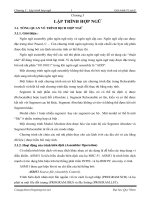
Displaying error codes
R
led
R
led
R
led
R
led
R
led
R
led
R
led
R
led
LED 7 LED 6 LED 5 LED 4 LED 3
LED 2 LED 1 LED 0
8051 Device
Port 2
Vcc
ULN2803A
9
P2.0 - Pin 8
P2.1 - Pin 7
P2.2 - Pin 6
P2.3 - Pin 5
P2.4 - Pin 4
P2.5 - Pin 3
P2.6 - Pin 2
P2.7 - Pin 1
Pin 11 - LED 0
Pin 12 - LED 1
Pin 13 - LED 2
Pin 14 - LED 3
Pin 15 - LED 4
Pin 16 - LED 5
Pin 17 - LED 6
Pin 18 - LED 7
For 25mA LEDs, R
led
= 120 Ohms
The forms of error reporting discussed here are low-level in nature and
are primarily intended to assist the developer of the application, or a
qualified service engineer performing system maintenance.
An additional user interface may also be required in your application to
notify the user of errors, in a more user-friendly manner.
COPYRIGHT © MICHAEL J. PONT, 2001-2003. Contains material from:
Pont, M.J. (2001) “Patterns for triggered embedded systems”, Addison-Wesley.
PES II - 35
Hardware resource implications
Timer
The scheduler requires one hardware timer. If possible, this should
be a 16-bit timer, with auto-reload capabilities (usually Timer 2).
Memory
This main scheduler memory requirement is 7 bytes of memory per
task.
Most applications require around six tasks or less. Even in a
standard 8051/8052 with 256 bytes of internal memory the total
memory overhead is small.
COPYRIGHT © MICHAEL J. PONT, 2001-2003. Contains material from:
Pont, M.J. (2001) “Patterns for triggered embedded systems”, Addison-Wesley.
PES II - 36
What is the CPU load of the scheduler?
• A scheduler with 1ms ticks
• 12 Mhz, 12 osc / instruction 8051
• One task is being executed.
• The test reveals that the CPU is 86% idle and that the
maximum possible task duration is therefore approximately
0.86 ms.
COPYRIGHT © MICHAEL J. PONT, 2001-2003. Contains material from:
Pont, M.J. (2001) “Patterns for triggered embedded systems”, Addison-Wesley.
PES II - 37
A scheduler with 1ms ticks,
running on a 32 Mhz (4 oscillations per instruction) 8051.
• One task is being executed.
• The CPU is 97% idle and that the maximum possible task
duration is therefore approximately 0.97 ms.
• Twelve tasks are being executed.
• The CPU is 85% idle and that the maximum possible task
duration is therefore approximately 0.85 ms.
COPYRIGHT © MICHAEL J. PONT, 2001-2003. Contains material from:
Pont, M.J. (2001) “Patterns for triggered embedded systems”, Addison-Wesley.
PES II - 38
Determining the required tick interval
In most instances, the simplest way of meeting the needs of the
various task intervals is to allocate a scheduler tick interval of 1 ms.
To keep the scheduler load as low as possible (and to reduce the
power consumption), it can help to use a long tick interval.
If you want to reduce overheads and power consumption to a
minimum, the scheduler tick interval should be set to match the
‘greatest common factor’ of all the task (and offset intervals).