Tài liệu The Plastic Product P4 docx
Bạn đang xem bản rút gọn của tài liệu. Xem và tải ngay bản đầy đủ của tài liệu tại đây (935.35 KB, 8 trang )
41
Parting Line Flash
Good molds have venting around most of, if not the whole length of the
parting line. As long as the stack and the vents are designed properly, there
should never be flash on the parting line. If flashing does occur despite a
properly designed and built mold, there could be a number of other causes:
The selected molding machine has not enough clamp force (tonnage)
for the projected area of the cavity and the required injection pressure or
was not adjusted properly. This is a rather common occurrence, especially
when the mold is installed in a low-tonnage machine (clamping force)
because a suitable machine was not available.
Flashing at the parting line could be caused by a poorly maintained and
out of alignment molding machine, which could be the result of poorly
adjusted tie bars, worn tie bar bushings, worn or bent machine platen
surfaces, poor hydraulic system, and so forth. Only too often a mold is
blamed for flashing when the real reason is a poorly maintained or a too
low tonnage machine.
There may be (hard to see) plastic caught between the mold faces.
Gaps Between Cavity and/or Core Parts and Inserts
Mold parts and inserts can be dimensioned for locational clearance fits
(Standard Geometrical Tolerancing); that is, they will probably always have
a clearance, but this clearance must never exceed a size where plastic could
flash into it. This means that the so-called standard fits are not always suitable
with larger mold components and inserts. Smaller tolerances than given with
“standard fits” must be specified for some mold dimension. This modified
method of tolerancing fits is quite suitable for the assembling of molds.
Because gates wear out in time and get easily damaged, often during startup
of the mold, molders prefer that the gate be in an insert, see Fig. 2.58, that
can be replaced when necessary, rather than rebuilding the entire cavity.
Welding a worn gate is sometimes successful, if done by experienced welders,
but in most cases, even the best weldment will be visible on the product,
especially on a highly polished surface. This kind of repair is generally not
recommended. Any gate insert will leave a circular witness line. It must be
pointed out to the customer before beginning the mold design that the mold
would be less expensive to build without an insert, but the costs of upkeep
will be much higher, especially with high production requirements, which in
the long run will affect the cost of the product.
Figure 2.59 shows a modular cavity (A), the matching cavity bottom (B),
and the beryllium-copper alloy gate insert (C) for the cavity bottom The
witness line will be a small circle around the gate.
It is also important to realize that a properly designed gate insert permits
better cooling around the gate which is very important for achieving a faster
molding cycle. The added cost of the insert can be easily justified with the
Figure 2.58 Typical cavity with and
without gate inserts
Cavity
Gate
insert
Cavity
bottom
Figure 2.59 Modular cavity
2.8 General Appearance of the Product
A common misconception is that if a
mold fits a machine it should be able
to run on it
Good
cooling
Witness
line
1281han02.pmd 28.11.2005, 10:4841
Previous Page
42
2 The Plastic Product
increased productivity of the mold. The cost of a gate insert may range
between $200 and $1,000 each.
Clearance of Ejector Pins and Ejector Sleeves
Ejector pins are always produced by mold part supply manufacturers with
specified, standard, close tolerances so that when the mold is built with the
bore dimensions for these pins, as suggested by the pin manufacturer, they
will not flash and they will always leave a witness line. The clearance between
ejector pin and bore is actually desirable, because it creates a good, self-
cleaning vent. Ejector pins (and sleeves) and the bore wherein they slide will
wear over time. Especially when abrasive plastics are molded, but also,
frequently, when the mold is poorly designed or built, the pins are allowed to
rub on the side of the bores. If the ejector plates are properly aligned, with
their mass suitably supported by guide pins (see Fig. 4.51 in Section 4.1.7.1)
and the ejector pins (or ejector sleeves) are allowed to float freely in their
retainer plates, there is little wear to expect. But even under the best
conditions, after the mold is in operation for a long time, the clearance in
the bores will increase, and the plastic will begin to flash around the pin.
Such flash may also create points of hang-up and prevent fully automatic
ejection.
The proper way to repair the mold is to increase the bore size and replace the
ejector pins with a larger size. Standard oversize pins are commercially
available, usually 0.13 mm (0.005 in.) larger in diameter than the original,
nominal standard sizes. Allowing space for oversize bores should be con-
sidered when designing the mold; this is sometimes difficult with small
technical products, where small pins barely clear the space between walls or
under ribs.
Note that some molders use double or even multiple ejection strokes to
overcome the problem of hanging up due to flashing; however, this adds
considerable time to the cycle, adds wear to the machine and mold, and is
not recommended.
Hiding the Gate Mark
Occasionally, to improve the appearance of the product, it may become
necessary to use certain “tricks” to hide the gate marks. A pinpoint gate mark
(vestige) from a 3-plate or a hot runner mold can be hidden inside an
ornament or inside the closed portion of a letter appearing on the same
surface (typically, inside a letter O, P, D, etc.); in other cases, an ornament
could be created around a gate, such as several concentric circles, with the
gate as the center. In some cases, where the vestige of a valve gate is on the
visible top surface near one end of the product, a similar “fake vestige” near
the opposite end can be created with an inserted round pin, which serves no
other purpose than to make the product appear symmetrical, which is usually
more pleasing to the eye.
Figure 2.60 Gate mark hidden in the letter
Y of this Playdoh lid
Consider the locations and sizes of
the ejector pins carefully. In many
molds, fewer pins of appropriate size
in more suitably placed locations
could save a lot on mold costs and
improve operation
1281han02.pmd 28.11.2005, 10:4842
43
2.8.4 Weld Lines
Weld lines are created when two semi-molten streams of plastic within the
cavity space intersect. They appear on the surface as more or less pronounced
lines. These streams may originate from two separate nozzles in the same
cavity, or when a projecting pin or other obstacle breaks the flow into two
separate streams. In some products, these weld lines can be objectionable for
aesthetic reasons; in others, they may be acceptable. When the plastic surface
is to be printed after molding, such lines could present an unacceptable visible
flaw. Note that a weld line also weakens the product, because the plastic
streams – by the time they rejoin – are already colder and may not fuse
sufficiently. Higher mold and melt temperatures can sometimes improve or
even eliminate a weld line; however, this means longer cycle times (less
productivity). When molding pigmented (colored, particularly metallic)
plastics, weld lines can show up very distinctly. Plastic always finds the easiest
path (“path of least resistance”) within the mold. Typically, a heavier rim or
ribs allows more and faster flow than the adjoining thinner walls, so that the
plastic, after rim or ribs are filled, will fill the remainder of the cavity space
from there (“back-fill”) and create weld lines where these flows meet. This is
an important consideration for locating the gate(s). If weld lines are created
by such conflux of plastic it is important to provide vents at these spots to let
any trapped air escape. These features add cost to the mold.
Location of Weld Lines
Usually, the location of weld lines can be quite accurately predicted by plain
logic or with the help a flow modeling computer program. If the area where
the weld line is expected to form is critical for strength, a change in the gate
location may be a way to change the location of a weld line. In addition, it
may be possible to facilitate the plastic flow to a certain path (e.g., by slightly
increasing a portion of the cross section of the flow path) so that the plastic
reaches the critical point and flows around it before the other stream is met,
thereby relocating the weld line to an area where it will do less harm to the
strength of the product. Such slight increase in the thickness may be hardly
noticeable and, while increasing the amount of plastic insignificantly, it
ensures a stronger product. Since this is a change to the product, the approval
of the product designer may be necessary.
In many cases, a weld line is unavoidable. Only its location can be influenced
by the location of the gate and flow leaders/ribs and changes in thickness of the
part. To improve the appearance and strength of a weld line, typically a molder
will increase mold temperature, injection speed, melt temperature, or venting.
2.8.5 Surface Defects (Flow Marks, Splay, Record
Grooves, Haze, Jetting, Hooks, and Ripples)
Figure 2.63 shows four examples of typical surface defects that are essentially
defects caused by improper settings of the molding machine.
2.8 General Appearance of the Product
Figure 2.61 Weld lines on cosmetic case.
The plastic flows from the gate through the
grill and rejoins afterwards, forming the
weld line
Figure 2.62 This lid for an ice cream
container has a cardboard insert and the
plastic is molded in a ring around it. The
weld line is formed opposite the gate
location
1281han02.pmd 28.11.2005, 10:4843
44
2 The Plastic Product
The surface may show unsightly flow marks as the plastic flows away from
the gate. This is often the case when injecting into the open surface of a
product. A simple remedy is to ensure that the plastic coming from the gate
is immediately broken up by “shooting” against the core if that is possible.
This is always the case with hot runner molds and with cold runner, 3-plate
molds where the gate is opposite the core. With 2-plate molds, if there is no
sidewall of the product, it is best to shoot against a core pin located in the
cavity space (a pin or projection either in the cavity or in the core).
Products with many thick and thin sections may also show such flow defects.
Slower injection and adjusting the temperatures and pressures may be the
only remedy. This will increase the cycle time and affect the cost of the
product.
2.8.6 Identification of the Molded Piece
Every molded piece should – and in some cases must – have certain identi-
fications molded into it. The product designer will sometimes specify the
location of some of the engravings, but often leave it to the mold maker to
decide their location, size, and style. The mold designer must know before
starting, which engravings will be required. Some of the markings could be
created by special, often standard inserts (e.g., the date – week, month, year
– when the product was molded); they should be located so that the date can
be changed easily without major work on the mold. These markings are often
mandatory for food packaging, pharmaceutical, and other products.
Typical markings, in addition to any specific instructions, are:
Identification of the seller of the product
Identification of the molder, if not the same as above
Resin type identification for recycling
Cavity (and mold) numbering (position, location)
Patent number, if applicable
Made in ______ (identification of country of origin)
Date of manufacture
Special information: “Food grade”, “Microwave safe”, “Dishwasher safe”,
etc.
Others as could be required by law
Logos
Product identification
Bar code
Figure 2.64 Identification of a molded piece
Drool
Figure 2.63 Typical surface defects
Excessive sink marks
Record grooves
1281han02.pmd 28.11.2005, 10:4844
45
In some countries, some of these markings are mandatory, and it is up the
product designer to specify what is obligatory and what is optional in the
countries where the product will be used and/or sold.
Occasionally, there is resistance to have cavity numbers shown, but it is
absolutely necessary for the molder to know from which cavity, and from
which mold a piece has originated to be able to find the cause of any defects.
If consecutive numbers are not desired, some code could be used for
identification of the stack from which a faulty piece has been ejected.
It is always difficult to add engravings to a mold or to make revisions to
existing engravings. If it is anticipated that changes are likely to come, the
mold designer should design the mold with the necessary inserts so that
changes can be made easier, or put it on an inexpensive part of the stack. It
may add some costs at the time of building of the mold, but will be much
less expensive than making changes to a finished mold. This is often the case
when the same mold could be used for products sold to different customers.
Every mold insert should be marked with the mold and cavity number to
ensure that after disassembling the mold for maintenance or repairs, the
various mold parts are assembled in the same relationship as before dis-
assembly.
2.9 Product Strength Requirements
Plastic products must not only “look good,” but they must also be strong
enough and suitable for the application for which they are intended. The
molding material (the plastic) is usually specified by the product designer to
create a product with all the desired properties. This material selection can
affect the selection of features to be built into the mold. Not every mold can
be used for every type of molding material. A mold that is ideal for one type
of plastic may not be suitable for another, or at least not perform as well. For
example, air ejection could be used for a product made from PP, but the
same product in PS would require a stripper ring ejection. A different plastic
from what was originally intended to use may also present difficulties in
filling and packing.
The addition of fillers to the plastic can increase the strength of the product
but will also affect the shrinkage factors, usually reducing them. This means
that the size of the product will be affected when molding a material different
from the one for which the mold was built. Fillers can be abrasive and wear
parts of the mold sooner than unfilled plastics. This can affect the mold
design and construction, therefore mold parts subject to erosion should be
easily replaceable when worn. It may also require the use of better wearing
steels. This is particularly important for gates in hot runner molds and all
other areas where the hot, abrasive plastic flows at high speed over the molding
surface, but this kind abrasive action can also be the case in molds with cold
runner gates. These provisions will increase the cost of the mold.
2.9 Product Strength Requirements
Every molded part should have a
unique identification such as a cavity
number
Every insert should be marked with
mold and cavity number
Typical wear points usually can be
foreseen and the affected mold parts
made easily accessible for servicing
and replacement
1281han02.pmd 28.11.2005, 10:4845
46
2 The Plastic Product
2.9.1 Gate Location to Increase Product Strength
Gate location is important for the ability to fill the mold. Some large cavities
may require two or more gates to properly fill, which of course affects the
cost of the hot runner system.
The gate location is also important because it determines the direction in
which the plastic molecules will be oriented within the molded product to a
large extent. In general, the strength of plastic in the direction of flow is
greater than in the direction across the flow. Near the gate, when the plastic
flows in all directions, the strength is relatively low and can be compared
with the low strength at a weld line. Therefore, if maximum longitudinal
strength is required in an elongated product, gating near the end of the
product is very important (see Fig. 2.65). Thin-walled products are especially
vulnerable to this difference in strength, because the thinner plastic cools
faster and does not have a chance to re-align the molecules randomly for
better strength in all directions, as is the case with heavier-wall products
where the plastic stays hot longer between the cooled outer layers and gives
the inside core of the plastic time to re-align.
It is important to recognize the importance of the gate location. It may be
easier (and cheaper) to locate the gates so as to employ the shortest runner
length (cold or hot runner), but this could result in lower strength of the
product, particularly with elongated products, which are subjected to bending
forces in use. There are also other issues that affect the gate location.
The gate needs to be hidden or recessed, so that any protruding gate
mark cannot hurt (scratch) anyone using the product (this is very
important in medical products)
A protruding gate mark could also be in the way of a paper label, which
will be applied there.
Some protruding gate marks are protected with gate rings for strength,
typically at the bottom of large containers (see Fig. 2.66).
2.10 Special Features
A big advantage of molding products from plastic is that different parts of a
product can be consolidated into one molding and that many features can
be molded in. Whether this is done for better appearance or for better
functioning and lower assembly costs of the final product, this makes it
sometimes more difficult for the design of the cavities and cores (see Fig. 2.68).
In addition, some designers, when redesigning a product which was originally
made from metals, do not appreciate or understand the intricacies and
problems of mold design and molding, especially if they are used to designing
for metals or other materials. It is therefore always suggested to scrutinize the
drawing for the proposed product to see if its design is appropriate for plastics.
Figure 2.65 Typical elongated products,
gated at or near the end for maximum
strength
Figure 2.66 Gate protection rings are used
to increase a pail’s impact resistance
1281han02.pmd 28.11.2005, 10:4846
47
2.10.1 Holes and Counter Bores for Assembly Screws
or Rivets
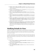
In general, it makes for more pleasant appearance if mounting screws, used
for example to fasten a cover to a base, are recessed, i.e., the screw head will
be below the surface of the cover. If the counter-bore for the screw head is
deep and its diameter is small, the core pin creating this counter-bore becomes
very difficult to cool efficiently and a redesign may be necessary in this area
(see [1] Section 5.2.4 for suggestions in this area).
Plastics lend themselves well for the use of self-tapping screws. The design
(dimensions) of screw holes must be to the specifications provided by the
manufacturer of such screws and the screws must be selected to suit the
plastic material with which they are used. The holes for the (usually small
size) screws are molded with very small core pins; these pins are very difficult
to cool or cannot be cooled at all. Because the hubs or walls where the screw
holes are located are much heavier than the adjoining product walls, the
cooling time will be longer than expected for the rest of the product. This
problem may result in grossly underestimating the molding cycle time and
lead to a mold with less productivity than expected. Many molds have been
built with excellent cooling in areas for which it was easy to provide cooling.
However, because there was no effective cooling at all near critical points,
such as some small core pins, they were a waste of effort and money. In other
words, despite the expensive (and unnecessary) good cooling for most areas,
such molds ended up having a very slow molding cycle because of poor
cooling in one area.
2.10.2 Hinges and Snaps for Assembly
Snapping two molded pieces together (or snapping one molded piece over a
metal piece) is an ideal application for plastics products.
Typical examples are containers for dairy products using a PE snap-on lid
over a PP container, a PE lid on metal can (coffee can), cell phone assemblies,
automotive applications, DVD cases, and many more. Some of these snaps
have a long, successful history and the dimensioning is well documented.
However, the designer is cautioned that such “snaps” depend on the amount
of shrinkage experienced (a) in the mold during cooling and (b) after ejection,
while cooling outside the machine. Also, from experience, a mold can produce
perfect (as expected) products in one machine, but not in another, which
could result in wrong snapping (holding) forces. More modern machines
can use higher injection pressures and speeds and can therefore also cycle
faster; in doing so, the shrinkage values will change. For example, when
receiving a repeat order for a mold (e.g., a lid), it will be correct to assume
that the steel dimensions of cavities and cores for the new mold will be the
same provided that the mold will run on the same or a similar machine.
However, if a more recent or better injection-molding machine will be used,
it will most likely be necessary to establish new core and cavity dimensions.
2.10 Special Features
Concentrate on the mold parts that
are difficult to cool. They determine
the productivity of the mold
Figure 2.67 DVD cases with hinges
Never locate a gate in a position that
will cause a weld line on a hinge
1281han02.pmd 28.11.2005, 10:4847
48
2 The Plastic Product
This can be costly and must be considered in estimating the mold cost. In
the long run, faster cycles can save a lot of money.
Figure 2.68 shows several samples of small and large over-caps for containers
with integral, hinged snap-on lids that snap close over the opening in the
over-cap. Some of these over-caps are produced with simple “up and down”
molds (A), some need intricate side cores (B) and much more complicated
molds. Also shown is a very large box (C) with snap-on lid, with an integral,
molded hinge connecting the two parts of the product.
A
B
C
Figure 2.68 Examples of over-caps for containers
1281han02.pmd 28.11.2005, 10:4848