Tài liệu The Plastic Product P3 docx
Bạn đang xem bản rút gọn của tài liệu. Xem và tải ngay bản đầy đủ của tài liệu tại đây (1.01 MB, 10 trang )
31
2.6.3 Fitting Surfaces of Mold Parts
This applies to all surfaces of mold parts that abut on other mold parts, but
are not in touch with plastic. Usually, grinding or fine machining surfaces are
required where the dimensions stack up and their sum must be held to close
tolerances. Otherwise, ordinary turning and milling surfaces are sufficient.
We have dwelled on the finishing of mold parts to highlight the importance
of properly specifying how and where a mold (mold part) needs to be finished
(polished) because of the cost. The mold designer should analyze whether
the finishing specifications shown on the product design are realistic and
really necessary for the functioning or use of the product and discuss it with
the product designer. This can result in great savings, reduced delivery time
and improved productivity (output of the mold).
All agreed-upon finish specifications must be shown on the finally approved
product drawing. SPE (Society of Plastics Engineers, www.socplas.org)
provides a series of standard finishing specifications, which can also be
translated into finish in microns (thousands of a millimeter). They are a good
method of specifying finishes, but additional information may be required
on the drawing to clearly specify for which areas these specifications apply.
The mold designer should never accept a general finish unless it is easy to
produce, or the cost of it will be factored in the mold cost.
2.7 Engravings
The term “engravings” covers lettering, lines, ornaments, logos, and others.
2.7.1 Engravings Versus Applied Labels
Engravings in the mold represent a one-time cost; therefore, in the long run,
the cost of the finished product is less than the cost of applying labels made
from paper or plastic film to the molded product. If the labels are applied in
a separate operation, this cost must be added to the cost of the product. In
some operations, the application of labels could be done “on-line”, with an
automatic applicator, in which case only the equipment and maintenance
costs need to be considered. In either case, the cost of the labels must be added.
We must not forget that the same product could be used for different end
user applications (for example, different chemicals are sold in containers of
the same size) and/or for different end users (manufacturers). In either case,
labels applied after molding would make more sense than changing mold
components for a different engraving. Whether to use all engraving, labels
alone, or part engraving and part labeling must be decided in view of the
quantities of pieces to be produced and the flexibility needed in each case.
There are other methods of applying information on a plastic product such
as printing, hot stamping, and others.
2.7 Engravings
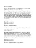
Figure 2.40 Engraved products
1281han02.pmd 28.11.2005, 10:4831
Previous Page
32
2 The Plastic Product
As a general guideline we can assume that the cost of the molded product
increases approximately
Little, when engraving
Approx. 10% with printing
Approx. 50–100% with labeling
Also factored into the considerations should be other methods of manu-
facturing, such as in-mold automatic insert molding of printed labels and
some other molding methods that from time to time have appeared on the
market. These specialized techniques should not be ruled out, especially if
the production quantities are such that the special equipment for such
methods can be economically justified. Although these types of molding will
not be discussed in this book, Section 4.1.10 provides illustrations of systems
for automatically inserting labels into molds.
2.7.2 Two-Color and Two-Material Engraving
Buttons (typewriter keys, pushbuttons, etc.) with two materials or colors
molded in one molding setup (quite complicated) are another method of
marking molded surfaces. Originally, these buttons or keys were molded with
(depressed) engraved “text” (alphabet, symbols) and the thus created molded
recesses were then filled with paint. This was expensive hand work; in addition,
raised engraving is very expensive to make in the mold (see below). Today,
most mass-produced keyboard keys for computers, etc. are printed by various
methods.
Two (and more) color molds will not be discussed here, because they are
rarely used today in lieu of engraving. However, two-color molding for many
other products (mostly automotive) is still much in use. The general principles
of anything discussed in this book do also apply to these molds.
2.7.3 Depth of Engravings
It is important to understand that engravings which are to appear depressed
(appearing engraved) in the surface of the product are created by raised
features in the mold. Conversely, engravings depressed (engraved) in the
mold appear as raised features in the product. It is amazing how many
product designers do not realize that it is fairly easy to engrave into a steel
surface, but very time-consuming (and costly) to create engravings
projecting from a surface.
Figure 2.41 Printed keyboard keys
Figure 2.42 Hot-stamped logos on
cosmetic cases give a multi-material look to
the products
1281han02.pmd 28.11.2005, 10:4832
33
Many designers, when confronted with these facts, confessed they did not
know that it makes such a difference, and readily changed their design to
“raised in the product”. The only time when it may be really necessary to
have the engraving depressed in the product is when the lettering will be
filled with paint, after molding, for better readability or special effects or for
special, artistic designs, usually associated with high-quality products, such
as technical enclosures for hand held devices (cell-phones, etc.) containers
for cosmetics (compacts) and so forth.
Occasionally, when the raised lettering in the product is objectionable, there
is always the possibility of depressing a “panel” and have the engraving on
this panel, so that the top of the engraving is level or slightly below the main
surface, see Fig. 2.43.
2.7.4 Font Style and Size of Artwork
For general applications, such as cavity marking or manufacturer’s identifi-
cation, the style (font) or size the lettering may not be very important. The
lettering should be (pleasantly) proportional to the size of the product and be
easily readable. The mold maker may have only a certain range of styles and
sizes available; using these will be less expensive. If the engraving has special
requirements, the product designer must supply the artwork from which the
necessary templates or models are made for machining. The mold designer
and product designer must agree on the form of artwork best suitable for
the mold maker, as there can be costs involved in preparing such artwork, in
the size (photo-enlargement), and material (Mylar film, etc.) required.
The smallest acceptable size of engraving should be considered. A suggested
minimum size is 8 pt, to be readily legible, but 6 pt could be required in
exceptional cases.
In all cases of engravings, it is also important to consider the cost of removing
the burrs (by hand or mechanically) after cutting the steel, to prevent
unsightly, fuzzy outlines of the engravings on the molded products.
2.7.5 Polarity of Engraving
We shall define positive engraving as any engraving such that will appear
“readable” to the user. Negative engraving is the inverted image, e.g., as
ordinary lettering would appear in a mirror. This may seem obvious but it
still does require some comments. Most engravings are viewed from the
outside of the product (top, side, or bottom), regardless of whether the plastic
is opaque, transparent, or translucent. In all these cases, the engraving must
be negative to appear in the molded piece as “readable” (positive). This is
also important where it may not appear as obvious, such as in the case of
logos or trademarks, which may appear to the casual observer to be symme-
trical but may have some asymmetrical features, which must be seen by the
user in the proper orientation (polarity).
Figure 2.43 Upper view: raised engraving
on top of product. Lower view: raised
engraving in depressed panel; t = wall
thickness of the product, H = height (depth)
of engraving
Figure 2.44 Picture of artwork
2.7 Engravings
1281han02.pmd 28.11.2005, 10:4833
34
2 The Plastic Product
Figure 2.45 Gate pad engraving
(bottom of container)
In some products molded from transparent or translucent plastics, the
required lettering or marking could be molded on the inside of the product,
so as to be read by the user through the plastic. In these cases, the engraving
must be positive in the mold steel. This is the case in measuring cups, if the
engraving is on the core.
2.7.6 Are the Locations Selected for Engraving
Practical?
The product designer usually places the lettering, lines, or symbols at locations
where they are best suited for the end user, but occasionally such engravings
could be difficult to produce by the mold maker in the location specified.
This could be the case where engraving inside a pocket in the mold would be
difficult or even impossible, and would require inserts or EDM requiring
special electrodes. In some cases, the engraving could be too close to the edge
of the mold steel, thereby increasing the risk of early failure of the mold steel
due to stress cracks. A minimum of 2 mm between any engraving and the
edge of the mold steel is suggested.
Here again, the mold designer and the product designer must work together
to find the most suitable compromise between product requirement and
mold cost.
2.7.7 Engravings in the Walls and Bottoms
of Products
Engravings can be either on the cavity wall or on the core (they could also be
on inserts in either cavity or core).
Engraving on the Outside of the Product (Engraved Cavities)
Containers usually require markings on the outside of the sidewalls or in the
bottom. Markings in the bottom are often required to show trademarks,
patents, product identification, batch identification, dates of manufacture,
or others. Engravings in the sides are occasionally required (usually with
transparent or translucent plastics) to indicate liquid levels inside a container.
Engraving into the bottom of a cavity is usually not difficult, especially if
most of the bottom of the cavity is an insert in the cavity block. Alternatively,
it is not too difficult or costly if inserts with the required engravings are
placed either in the solid cavity bottom, or within a large cavity bottom insert
(“inserts within an insert”). Serious problems can arise when laying out the
cooling circuits in such complex cavity bottoms. Good cooling in the gate
area is very important for fast molding cycles; inserts make it more difficult
to lay out efficient cooling channels. A poorly cooled cavity bottom, especially
near the gate, will result in a longer molding cycle. In this case, the preferred
method is to have a solid insert for much of the cavity bottom. If there are
1281han02.pmd 28.11.2005, 10:4834
35
changes required in the engraving, it is not too difficult or expensive to change
the bottom. This may result in having and storing a number of different
bottoms for the cavity for the various applications or end users of the product,
which are also costs to be considered.
Mechanical engraving in the bottom of deep cavities is always difficult, because
long unsupported engraving cutters will by necessity operate at a slower speed
for the required accuracy and cleanliness of cut. Long EDM electrodes can
be used, although they are slow and expensive; however, this method has the
advantage that it can be done even after the cavity is finished.
A method not much used today is the hobbing of the engraving into the
bottom of a cavity. This method was used extensively in molds built about
the middle of the last century (both for small compression and injection
mold cavities). This method can be used only in soft steels and requires special
heat treatment (carburizing and hardening) of the steel after hobbing. It is
still occasionally used today.
The injected plastic, as it cools inside the mold, shrinks away from the cavity
wall and, provided the depth of engravings into the cavity walls is not too
deep, there is usually no problem with ejection. As the product shrinks toward
the core, it will not “hang up” in the cavity as the mold opens. However, the
clean withdrawal of the molded piece from the cavity depends also very much
on the draft angle of the sidewall, on the wall thickness of the product in this
area, and on the type of plastic used.
There is no easy formula to indicate what is possible and what is not, but
as a general rule it can be stated that
Any engraving (by chip removing or EDM) in the sidewall inside a
cavity, especially in a small one, is very difficult and can be very
expensive. Shallow engravings “burnt” with EDM are easier to achieve;
but there is the problem of matching the engraved electrodes to the
shape (curvature) of the cavity wall so that the depressions created
with EDM are uniform both in depth and appearance and do not
exceed the critical depth beyond which the product can not pull out
of the cavity. The suggested maximum depth is in the order of 0.1 mm
(0.004 in.) or even less for difficult cases, such as explained in the
following points.
Walls with heavier thickness allow deeper engravings because they
shrink more and let the product withdraw more away from the cavity.
The greater the shrinkage factor, the easier the engraved portion pulls
away from the cavity.
The greater the taper of the sidewalls, the easier will the product pull
out of the cavity. Engravings in sidewalls with tapers of less than
approx. 5° are more difficult to withdraw than from walls with larger
tapers.
2.7 Engravings
Engravings into the sidewall of the
cavity are always difficult and
expensive
1281han02.pmd 28.11.2005, 10:4835
36
2 The Plastic Product
Hard plastics such as PS will offer more resistance if they were “caught”
by the edge of too deep a depression than would be more flexible
plastics, such as PP and PE. However, there are many molds success-
fully producing even thin-walled PS products with decorations on
their outside walls.
The angle and shape of the sides of the engraving within the sidewall
of the cavity must be so that it offers little resistance as the mold opens
and the edge of the engraved projection in the product slides past the
engraved depression in the sidewall.
Any deeper engravings in the side walls, or where there is not enough draft
angle, will require to place the engravings either on moving side cores in the
cavity or on split cavities. Both methods would require more space, much
larger molds, and add considerably to the mold cost; such molds will usually
also potentially produce more scrap, require longer molding cycles, and
thereby increase the cost of the product even more.
Figure 2.46 shows heavy-walled tumblers engraved with an artistic pattern on
the outside, produced by engraving (texturizing) the inside of the cavity. This
engraving is not deep enough to require a split cavity. Note the stacking lugs
visible through the plastic. They are used to stack the parts in a dense pattern.
Engravings Inside of the Product (Engraved Cores)
The following comments apply to engravings into the top or the sides of the
core.
Engravings in the sides are often required with transparent or translucent
plastics, e.g., to indicate liquid levels inside a container (measuring cups,
vials, etc.). The markings are usually lines indicating the proper height and
lettering to identify the values. Such products are made mostly from clear
polystyrene (PS), SAN, Acrylic, or polycarbonate (PC) that have low shrinkage
factors. This makes it relatively easy to calculate the dimensions where the
measuring lines should be located. If such products are made from high-
shrinkage materials, such as PE or PP, the high shrinkage factor makes it
more difficult to predetermine the proper location for the level markers. In
such cases, especially if the accuracy of the measuring lines is important, it
may be necessary to finish the mold first, complete with the lettering, but to
engrave the measuring lines only after the mold has been tested and runs on
an optimal cycle, because the volume of the container can vary substantially
when operating at different operating conditions of the mold.
Except for very stiff plastics, such as PS, SAN, or PC, and sometimes with air
ejection of even softer plastics, lines and lettering on the core present fewer
problems, because the plastic will stretch during ejection and let the plastic
slide out of the engravings. This is possible because at the time of ejection, the
cavity has already moved away from the product and there is ample room for
the plastic to stretch during ejection. However, the deeper the engraving, the
Figure 2.46 Tumblers engraved on the
outside
1281han02.pmd 28.11.2005, 10:4836
37
more important it is to make sure that the sides of the engravings are tapered
and/or rounded sufficiently to allow easy sliding out of the engravings. The
draft of container sidewalls can be quite small; a 1° taper could be acceptable
as long as the engraving is not too deep and the side of the engraving in the
direction of the ejection is smooth and chamfered or rounded.
Engraving into the side of a core is usually not difficult to achieve. The depth
should be in the order of 0.1 mm, but less is recommended for small draft
angles of the core. While it is feasible to produce raised “engraving” on the
core, this is extremely difficult to machine and then to finish the molding
surface of the core, and would therefore make for a very expensive mold.
The top of the core can be a good location to engrave the cavity number; it is
easy to produce and is frequently done in technical products and enclosures.
The designer must be sure that it can be easily read. If it is to be read from
the inside, the engraving must be negative, if it is to be read from the outside
(through the plastic), the engraving must be positive.
2.8 General Appearance of the Product
2.8.1 Flatness
It is usually easy to machine a flat surface; however, where very high polish is
required, common polishing practices can result in waviness of the surface,
which may not be acceptable for products requiring near-perfect flat areas
with optical clarity. In such cases it may be necessary to provide the mold
with inserts for the areas requiring the optical finish; they can then be polished
separately, on appropriate lapping equipment, which can guarantee flatness.
A typical example is the top surface – both on the core and the cavity side –
of Petri dish bottoms and lids made from crystal PS.
Flat surfaces may be easy to machine but molding them can be a problem,
particularly when materials, such as PE or PP, with high heat content and
low thermal conductivity are used (see Appendix). Taking this into considera-
tion is especially important when the products are to be ejected as early as
possible to achieve fast molding cycles, i.e., while the products are still warm
but rigid enough to allow ejection without damage. A flat, relatively large
area in the mold is usually easier to cool than corner areas or heavy rims or
intricate sections in the product. However, the surrounding, often thicker
and almost always poorer cooled areas stay hot longer and will continue to
shrink after ejection and thereby tend to deform the already cold, flat areas.
Typical examples are rectangular flat trays or other flat shapes surrounded
by heavier rims; such rims stay warm longer and distort the flat areas while
they cool down to room temperature.
There are several approaches to solve this problem, but as always, they needs
full cooperation between the mold designer and the product designer. The
following are some typical examples of these approaches:
2.8 General Appearance of the Product
Figure 2.47 Flat parts can look like potato
chips if the mold and part are not designed
properly. A stepped ring was added to the
part to eliminate warpage
Figure 2.48 Petri dishes require optical
clarity and flatness
Figure 2.49 Flow leaders are used to aid in
even filling and to avoid warpage
1281han02.pmd 28.11.2005, 10:4837
38
2 The Plastic Product
The flat surfaces at the bottom of a container can be designed in the
mold as “curved” (or arched) so that the plastic, as it cools outside the
mold, will shrink to a less arched shape or even become flat (see Fig. 2.50).
If it does not matter to the appearance and/or the usefulness of the
product, this is a preferred solution. The curvature of the arch must be
selected to suit the anticipated cycle time. It is suggested to ask the product
designer for a wide tolerance on the curvature of the arch so that it will
be still acceptable for the purpose of the product, regardless of the actual
shrinking experienced, which may change with changes in the molding
conditions and with the plastic batches.
Note that with typical small containers, such as drinking cups or cottage
cheese containers, even with good cooling and equal thickness walls, the
bottom, when molded in a flat bottom mold, will pull towards the center
and deform (pull) the sidewalls inwards as the product continues to cool
outside the mold. This deformation may be objectionable. In such cases,
the arching of the bottom of the mold is absolutely necessary.
A flat surface of a lid can be modified by adding some steps or “ex-
pansion loops” so that, as the top of the lid shrinks, the steps or loops
will bend due to the pull from the shrinking and prevent warping of
the lid. This is of special advantage with large lids as for pails, etc. (see
Fig. 2.51).
Large, especially rectangular trays or lids that must be flat are always
difficult to keep from warping (“potato chipping”). It is very important
that an equal wall thickness throughout the tray is maintained so that
there are no warmer pockets of plastic, which will take longer to cool
and shrink after the rest of the molded piece is cooled. If the rim must be
thicker, more emphasis must be given to the cooling of the thick areas so
that all the plastic in the mold is cooled evenly. If this is not the case,
longer cycle times will be required to achieve flatness, or costly shrinking
fixtures may have to be planned.
It is also important that the flow lengths from the gate(s) to the rim are
as symmetrical as possible to permit the plastic to arrive to all parts of
the rim at the same time. This depends also on the thickness of the
product, where heavier sections permit easier and faster flow. This can
affect the selection of the hot runner system (e.g., using more than one
drop) and adds costs to the mold.
Figure 2.52 shows how the flow in a tray can be improved by machining
so-called “flow leaders” into the cavity or core, which are slight thickening
in the wall thickness in those areas which should flow faster to equalize
the filling pattern in a mold. Such thickening will add a very small amount
of plastic that can hardly be seen but will ensure better, less warping
trays. Flow analysis of such a product will show where such flow leaders
are required. In Fig. 2.52, T2 may be 10% greater than the wall thickness
T1 and the width of the flow leader would range from approx. 10–20 mm
(0.38–0.75 in.).
Figure 2.50 Schematic of cup with arched
bottom.
Figure 2.51 Lids with added steps or loops
Figure 2.52 Tray with added flow leaders
steel
dimensions
plastic
after
shrinkage
1281han02.pmd 28.11.2005, 10:4838
39
2.8.2 Sinks and Voids
Sinks (“sink marks”) are surface flaws (imperfections)
of the product resulting from either incomplete filling
during injection, excessive local shrinkage, or a com-
bination of both. During injection, the hot plastic flows
through the cavity space in contact with the cooled
mold walls. This causes the plastic layer near the walls
to solidify, thereby reducing the passage for the flow;
it requires more “effort” (higher pressure, higher melt,
and/or higher mold temperature) to completely fill the
subsequent portions of the cavity space.
Figure 2.32 shows the plastic flow through the cavity space. The frozen plastic
layers close to the cold walls reduce the passage through which the plastic
has to flow on its way to fill the cavity.
The shrinkage factor must also be considered: To avoid poor quality products
(voids) and/or unsightly shrink marks caused by the shrinkage as the plastic
cools, pressure must be kept on the plastic already in the cavity space with
the so-called “injection hold” pressure to add more plastic into the cavity
space and make up the “lost” volume due to cooling. This is useful only as
long as the gate is not frozen, i.e., as long as plastic can still pass through the
gate. The hold time adds to the cycle time and adds cost to the products.
Ideally, for best flow, the cross section through which the plastic flows away
from the gate should be largest near the gate and from there gradually
diminish toward the end of the flow. However, this is not practical because a
lot of plastic would be wasted. The next best thing is to make sure that, at
least, the same cross section is maintained throughout the mold; this is not
always possible because of the requirements of the product, but it should be
attempted.
The possibly worst condition is if a heavy area must be filled after the plastic
has passed through a long, narrow path and has suffered a large “pressure
drop”. Such remote heavy sections (typically, the rim of the product), even
when they are completely filled, see much lower injection pressures and
because the amount of shrinkage is greatest where the pressure is the lowest,
these areas will experience much shrinkage and result in sink marks or voids
(more about rim shapes in Section 3.8.7.1).
Sinks and voids appear often at the intersection of ribs and walls or in general
at any localized thickening of the plastic required for functional reasons,
such as hubs, and so forth. Because the thick section of the plastic remains
hot longer than the thinner sections, the plastic will continue to shrink there.
While the plastic is still relatively soft, it will pull the already more or less
cooled surface towards the center of the heavy, hot section, thereby creating
dips in the nearest surfaces. In many applications, a sink on a surface visible
to the user may be acceptable, but it should be agreed upon before designing
the mold how much of a sink is acceptable as well as its probable location.
Figure 2.53 Plastic flow through the cavity
space
Cooling lines
Melt front
Thickness
Fountain flo
w
Velocity
profile
Frozen layers
2.8 General Appearance of the Product
Figure 2.55 Intersections of ribs and thick
sections can cause sinks or voids
Figure 2.54 Automotive grill molded with
8 gates. The left side shows a filled part and
the right side a short shot. Venting was
required where the flow fronts meet to
resolve filling issues
1281han02.pmd 28.11.2005, 10:4839
40
2 The Plastic Product
The alternative is either to increase the injection pressure, which may not
always be possible, especially with older injection molding machines (or the
machine may not have enough clamp force to keep the mold closed against
the higher pressures), or to raise the temperatures of the melt or/and the
mold and use longer injection hold pressure cycles, all of which will result in
longer molding cycles and higher product costs.
If the plastic surface is already so stiff that it cannot be pulled in (or “sink”),
the still hot plastic will shrink away from the center toward this stiffer outer
skin and will create a “void”. A void is a hollow space inside the plastic and
contains a vacuum. In opaque plastics a void cannot be seen, but it can be
undesirable because it weakens the plastic, similar to porosity. Such a weak
spot, e.g., in a hub designed to receive a screw, would not be as strong as
expected.
If a transparent or translucent plastic contains a void, it is visible and can
look like a chain of round or elongated bubbles near the center of the heavy
section. To eliminate this defect, the molding conditions must be changed to
ensure that injection pressure is maintained in this critical area, often
requiring higher temperatures and resulting in longer cycle times. To remedy
this problem, the product design should be modified to eliminate any thick
spot(s).
Voids can be easily seen by cutting the suspect section with a saw or by drilling
a small hole into it from the nearest surface while holding the product under
the surface of a pail of colored water. As the drill breaks into the void, the
water is sucked past the drill into the void and can be seen as the colored
fluid fills it.
This is especially important if the customer has been quoted a specific cycle
time (a more detailed discussion about this subject can be found in [1] or in
any book on product design with plastics).
2.8.3 Witness Lines
Witness lines appear on the product wherever mold parts or inserts join on
the molding surface. No matter how good the fit of the mold parts and how
well polished the surface is at this spot, there will always be a more or less
fine line visible on the product. When the gap between the mold parts is
too large, it will flash, i.e., the plastic will enter the gap during injection,
and if it can pull out during ejection, it will be an unsightly thin projection
from the surface of the molded piece. At best, it may not affect the overall
appearance or serviceability of the product, but it is still the sign of poor
workmanship.
In general, gaps in the mold of less than 0.01 to 0.03 mm (0.0004 to
0.0012 in.) will not flash, depending on the type of plastic, the melt
temperature, and the injection pressure.
The possibility of voids or any
potential defects caused by heavy
sections in a product must be
discussed at the time a job is started,
and not after the mold is completed
Figure 2.56 Creation of a sink or void
Figure 2.57 The gate insert witness line
can clearly be seen on this worn insert for a
specimen cup lid
1281han02.pmd 28.11.2005, 10:4840
Next Page