Tài liệu SMART ANTENNAS ppt
Bạn đang xem bản rút gọn của tài liệu. Xem và tải ngay bản đầy đủ của tài liệu tại đây (3.14 MB, 458 trang )
CRC PRESS
Boca Raton London New York Washington, D.C.
Lal Chand Godara
SMART
ANTENNAS
© 2004 by CRC Press LLC © 2004 by CRC Press LLC
THE ELECTRICAL ENGINEERING
AND APPLIED SIGNAL PROCESSING SERIES
Edited by Alexander Poularikas
The Advanced Signal Processing Handbook:
Theory and Implementation for Radar, Sonar,
and Medical Imaging Real-Time Systems
Stergios Stergiopoulos
The Transform and Data Compression Handbook
K.R. Rao and P.C. Yip
Handbook of Multisensor Data Fusion
David Hall and James Llinas
Handbook of Neural Network Signal Processing
Yu Hen Hu and Jenq-Neng Hwang
Handbook of Antennas in Wireless Communications
Lal Chand Godara
Noise Reduction in Speech Applications
Gillian M. Davis
Signal Processing Noise
Vyacheslav P. Tuzlukov
Digital Signal Processing with Examples in M
ATLAB
®
Samuel Stearns
Applications in Time-Frequency Signal Processing
Antonia Papandreou-Suppappola
The Digital Color Imaging Handbook
Gaurav Sharma
Pattern Recognition in Speech and Language Processing
Wu Chou and Biing-Hwang Juang
Propagation Handbook for Wireless Communication System Design
Robert K. Crane
Nonlinear Signal and Image Processing: Theory, Methods, and Applications
Kenneth E. Barner and Gonzalo R. Arce
Smart Antennas
Lal Chand Godara
© 2004 by CRC Press LLC © 2004 by CRC Press LLC
Forthcoming Titles
Soft Computing with MATLAB
®
Ali Zilouchian
Signal and Image Processing in Navigational Systems
Vyacheslav P. Tuzlukov
Wireless Internet: Technologies and Applications
Apostolis K. Salkintzis and Alexander Poularikas
© 2004 by CRC Press LLC © 2004 by CRC Press LLC
This book contains information obtained from authentic and highly regarded sources. Reprinted material is quoted with
permission, and sources are indicated. A wide variety of references are listed. Reasonable efforts have been made to publish
reliable data and information, but the author and the publisher cannot assume responsibility for the validity of all materials
or for the consequences of their use.
Neither this book nor any part may be reproduced or transmitted in any form or by any means, electronic or mechanical,
including photocopying, microfilming, and recording, or by any information storage or retrieval system, without prior
permission in writing from the publisher.
The consent of CRC Press LLC does not extend to copying for general distribution, for promotion, for creating new works,
or for resale. Specific permission must be obtained in writing from CRC Press LLC for such copying.
Direct all inquiries to CRC Press LLC, 2000 N.W. Corporate Blvd., Boca Raton, Florida 33431.
Trademark Notice: Product or corporate names may be trademarks or registered trademarks, and are used only for
identification and explanation, without intent to infringe.
Visit the CRC Press Web site at www.crcpress.com
© 2004 by CRC Press LLC
No claim to original U.S. Government works
International Standard Book Number 0-8493-1206-X
Library of Congress Card Number 2003065210
Printed in the United States of America 1 2 3 4 5 6 7 8 9 0
Printed on acid-free paper
Library of Congress Cataloging-in-Publication Data
Godara, Lal Chand.
Smart antennas / Lal Chand Godara.
p. cm. — (Electrical engineering & applied signal processing)
Includes bibliographical references and index.
ISBN 0-8493-1206-X (alk. paper)
1. Adaptive antennas. I. Title. II. Electrical engineering and applied signal processing
series; v. 15.
TK7871.67.A33G64 2004
621.382′4—dc22 2003065210
© 2004 by CRC Press LLC
Dedication
With love to Saroj
© 2004 by CRC Press LLC
Preface
Smart antennas involve processing of signals induced on an array of sensors such as
antennas, microphones, and hydrophones. They have applications in the areas of radar,
sonar, medical imaging, and communications.
Smart antennas have the property of spatial filtering, which makes it possible to receive
energy from a particular direction while simultaneously blocking it from another direction.
This property makes smart antennas a very effective tool in detecting and locating an
underwater source of sound such as a submarine without using active sonar. The capacity
of smart antennas to direct transmitting energy toward a desired direction makes them
useful for medical diagnostic purposes. This characteristic also makes them very useful
in canceling an unwanted jamming signal. In a communications system, an unwanted
jamming signal is produced by a transmitter in a direction other than the direction of the
desired signal. For a medical doctor trying to listen to the sound of a pregnant mother’s
heart, the jamming signal is the sound of the baby’s heart.
Processing signals from different sensors involves amplifying each signal before com-
bining them. The amount of gain of each amplifier dictates the properties of the antenna
array. To obtain the best possible cancellation of unwanted interferences, the gains of these
amplifiers must be adjusted. How to go about doing this depends on many conditions
including signal type and overall objectives. For optimal processing, the typical objective
is maximizing the output signal-to-noise ratio (SNR). For an array with a specified
response in the direction of the desired signal, this is achieved by minimizing the mean
output power of the processor subject to specified constraints. In the absence of errors,
the beam pattern of the optimized array has the desired response in the signal direction
and reduced response in the directions of unwanted interference.
The smart antenna field has been a very active area of research for over four decades.
During this time, many types of processors for smart antennas have been proposed and
their performance has been studied. Practical use of smart antennas was limited due to
excessive amounts of processing power required. This limitation has now been overcome
to some extent due to availability of powerful computers.
Currently, the use of smart antennas in mobile communications to increase the capacity
of communication channels has reignited research and development in this very exciting
field. Practicing engineers now want to learn about this subject in a big way. Thus, there
is a need for a book that could provide a learning platform. There is also a need for a
book on smart antennas that could serve as a textbook for senior undergraduate and
graduate levels, and as a reference book for those who would like to learn quickly about
a topic in this area but do not have time to perform a journal literature search for the
purpose.
This book aims to provide a comprehensive and detailed treatment of various antenna
array processing schemes, adaptive algorithms to adjust the required weighting on anten-
nas, direction-of-arrival (DOA) estimation methods including performance comparisons,
diversity-combining methods to combat fading in mobile communications, and effects of
errors on array system performance and error-reduction schemes. The book brings almost
all aspects of array signal processing together and presents them in a logical manner. It
also contains extensive references to probe further.
© 2004 by CRC Press LLC
After some introductory material in Chapter 1, the detailed work on smart antennas
starts in Chapter 2 where various processor structures suitable for narrowband field are
discussed. Behavior of both element space and beamspace processors is studied when
their performance is optimized. Optimization using the knowledge of the desired signal
direction as well as the reference signal is considered. The processors considered include
conventional beamformer; null-steering beamformer; minimum-variance distortionless
beamformer, also known as optimal beamformer; generalized side-lobe canceller; and
postbeamformer interference canceler. Detailed analysis of these processors in the absence
of errors is carried out by deriving expressions for various performance measures. The
effect of errors on these processors has been analyzed to show how performance degrades
because of various errors. Steering vector, weight vector, phase shifter, and quantization
errors are discussed.
For various processors, solution of the optimization problem requires knowledge of the
correlation between various elements of the antenna array. In practice, when this infor-
mation is not available an estimate of the solution is obtained in real-time from received
signals as these become available. There are many algorithms available in the literature
to adaptively estimate the solution, with conflicting demands of implementation simplicity
and speed with which the solution is estimated. Adaptive processing is presented in
Chapter 3, with details on the sample matrix inversion algorithm, constrained and uncon-
strained least mean squares (LMS) algorithms, recursive LMS algorithm, recursive least
squares algorithm, constant modulus algorithm, conjugate gradient method, and neural
network approach. Detailed convergence analysis of many of these algorithms is presented
under various conditions to show how the estimated solution converges to the optimal
solution. Transient and steady-state behavior is analyzed by deriving expressions for
various quantities of interest with a view to teach the underlying analysis tools. Many
numerical examples are included to demonstrate how these algorithms perform.
Smart antennas suitable for broadband signals are discussed in Chapter 4. Processing
of broadband signals may be carried out in the time domain as well as in the frequency
domain. Both aspects are covered in detail in this chapter. A tapped-delay line structure
behind each antenna to process the broadband signals in the time domain is described
along with its frequency response. Various constraints to shape the beam of the broadband
antennas are derived, optimization for this structure is considered, and a suitable adaptive
algorithm to estimate the optimal solution is presented. Various realizations of time-
domain broadband processors are discussed in detail along with the effect that the choice
of origin has on performance. A detailed treatment of frequency-domain processing of
broadband signals is presented and its relationship with time-domain processing is estab-
lished. Use of the discrete Fourier transform method to estimate the weights of the time-
domain structure and how its modular structure could help reduce real-time processing
are described.
Correlation between a desired signal and unwanted interference exists in situations of
multipath signals, deliberate jamming, and so on, and can degrade the performance of an
antenna array processor. Chapter 5 presents models for correlated fields in narrowband
and broadband signals. Analytical expressions for SNRs in both narrowband and broad-
band structures of smart antennas are derived, and the effects of several factors on SNR
are explored, including the magnitude and phase of the correlation, number of elements
in the array, direction and level of the interference source and the level of the uncorrelated
noise. Many methods are described to decorrelate the correlated sources, and analytical
expressions are derived to show the decorrelation effect of the proposed techniques.
In Chapter 6, various DOA estimation methods are described, followed by performance
comparisons and sensitivity analyses. These estimation tools include spectral estimation
methods, minimum variance distortionless response estimator, linear prediction method,
© 2004 by CRC Press LLC
maximum entropy method, maximum likelihood method, various eigenstructure methods
including many versions of MUSIC algorithms, minimum norm methods, CLOSEST
method, ESPRIT method, and weighted subspace fitting method. This chapter also con-
tains discussion on various preprocessing and number-of-source estimation methods.
In the first six chapters, it is assumed that the directional signals arrive from point
sources as plane wave fronts. In mobile communication channels, the received signal is a
combination of many components arriving from various directions due to multipath
propagation resulting in large fluctuation in the received signals. This phenomenon is
called fading. In Chapter 7, a brief review of fading channels is presented, distribution of
signal amplitude and received power on an antenna is developed, analysis of noise- and
interference-limited single-antenna systems in Rayleigh and Nakagami fading channels
is presented by deriving results for average bit error rate and outage probability. The
results show how fading affects the performance of a single-antenna system.
Chapter 8 presents a comprehensive analysis of diversity combining, which is a process
of combining several signals with independent fading statistics to reduce large attenuation
of the desired signal in the presence of multipath signals. The diversity-combining schemes
described and analyzed in this chapter include selection combiner, switched diversity
combiner, equal gain combiner, maximum ratio combiner, optimal combiner, generalized
selection combiner, cascade diversity combiner, and macroscopic diversity combiner. Both
noise-limited and interference-limited systems are analyzed in various fading conditions
by deriving results for average bit error rate and outage probability.
© 2004 by CRC Press LLC
Acknowledgments
I owe special thanks to Jill Paterson for her diligent and professional job of typing this
book from my handwritten manuscript.
I am most grateful to my wife Saroj for her love, understanding, and patience, and my
daughter Pankaj and son Vikas for their constant encouragement, which provided the
necessary motivation to complete the project.
© 2004 by CRC Press LLC
The Author
Lal Chand Godara, Ph.D., is Associate Professor at University College, the University of
New South Wales, Australian Defense Force Academy, Canberra, Australia. He received
the B.E. degree from Birla Institute of Technology and Science, Pilani, India in 1975; the
M.Tech. degree from Indian Institute of Science, Banglore, India in 1977; the Ph.D. degree
from the University of Newcastle, NSW, Australia in 1984; and the M.HEd. degree from
The University of New South Wales, Australia.
Professor Godara has had visiting appointments at Stanford University, Yale University,
and Syracuse University. His research interests include adaptive antenna array processing
and their application to mobile communications. Included among his many publications
are two significant papers in the Proceedings of the IEEE. Prof. Godara edited Handbook of
Antennas for Wireless Communications, published by CRC Press in 2002.
Professor Godara is a Senior Member of the IEEE and a Fellow of the Acoustical Society
of America. He was awarded the University College Teaching Excellence Award in 1998.
Some of his activities/achievements in the IEEE included: Associate Editor, IEEE Trans-
actions on Signal Processing (1998-2000); IEEE Third Millennium Medal (2000); and Member,
SPS Sensor Array and Multichannel Technical Committee (2000-2002). He founded the
IEEE Australian Capital Territory Section (1988) and served as its founding Chairman for
three years (1988–1991). He served as Chairman of the IEEE Australian Council from
1995 to 1996.
© 2004 by CRC Press LLC
Contents
1
Introduction
1.1 Antenna Gain
1.2 Phased Array Antenna
1.3 Power Pattern
1.4 Beam Steering
1.5 Degree of Freedom
1.6 Optimal Antenna
1.7 Adaptive Antenna
1.8 Smart Antenna
1.9 Book Outline
References
2
Narrowband Processing
2.1 Signal Model
2.1.1 Steering Vector Representation
2.1.2 Eigenvalue Decomposition
2.2 Conventional Beamformer
2.2.1 Source in Look Direction
2.2.2 Directional Interference
2.2.3 Random Noise Environment
2.2.4 Signal-to-Noise Ratio
2.3 Null Steering Beamformer
2.4 Optimal Beamformer
2.4.1 Unconstrained Beamformer
2.4.2 Constrained Beamformer
2.4.3 Output Signal-to-Noise Ratio and Array Gain
2.4.4 Special Case 1: Uncorrelated Noise Only
2.4.5 Special Case 2: One Directional Interference
2.5 Optimization Using Reference Signal
2.6 Beam Space Processing
2.6.1 Optimal Beam Space Processor
2.6.2 Generalized Side-Lobe Canceler
2.6.3 Postbeamformer Interference Canceler
2.6.3.1 Optimal PIC
2.6.3.2 PIC with Conventional Interference Beamformer
2.6.3.3 PIC with Orthogonal Interference Beamformer
2.6.3.4 PIC with Improved Interference Beamformer
2.6.3.5 Discussion and Comments
2.6.3.5.1 Signal Suppression
2.6.3.5.2 Residual Interference
2.6.3.5.3 Uncorrelated Noise Power
2.6.3.5.4 Signal-to-Noise Ratio
© 2004 by CRC Press LLC
2.6.4 Comparison of Postbeamformer Interference Canceler with Element
Space Processor
2.6.5 Comparison in Presence of Look Direction Errors
2.7 Effect of Errors
2.7.1 Weight Vector Errors
2.7.1.1 Output Signal Power
2.7.1.2 Output Noise Power
2.7.1.3 Output SNR and Array Gain
2.7.2 Steering Vector Errors
2.7.2.1 Noise-Alone Matrix Inverse Processor
2.7.2.1.1 Output Signal Power
2.7.2.1.2 Total Output Noise Power
2.7.2.1.3 Output SNR and Array Gain
2.7.2.2 Signal-Plus-Noise Matrix Inverse Processor
2.7.2.2.1 Output Signal Power
2.7.2.2.2 Total Output Noise Power
2.7.2.2.3 Output SNR
2.7.2.3 Discussion and Comments
2.7.2.3.1 Special Case 1: Uncorrelated Noise Only
2.7.2.3.2 Special Case 2: One Directional Interference
2.7.3 Phase Shifter Errors
2.7.3.1 Random Phase Errors
2.7.3.2 Signal Suppression
2.7.3.3 Residual Interference Power
2.7.3.4 Array Gain
2.7.3.5 Comparison with SVE
2.7.4 Phase Quantization Errors
2.7.5 Other Errors
2.7.6 Robust Beamforming
Notation and Abbreviations
References
3
Adaptive Processing
3.1 Sample Matrix Inversion Algorithm
3.2 Unconstrained Least Mean Squares Algorithm
3.2.1 Gradient Estimate
3.2.2 Covariance of Gradient
3.2.3 Convergence of Weight Vector
3.2.4 Convergence Speed
3.2.5 Weight Covariance Matrix
3.2.6 Transient Behavior of Weight Covariance Matrix
3.2.7 Excess Mean Square Error
3.2.8 Misadjustment
3.3 Normalized Least Mean Squares Algorithm
3.4 Constrained Least Mean Squares Algorithm
3.4.1 Gradient Estimate
3.4.2 Covariance of Gradient
3.4.3 Convergence of Weight Vector
3.4.4 Weight Covariance Matrix
3.4.5 Transient Behavior of Weight Covariance Matrix
© 2004 by CRC Press LLC
3.4.6 Convergence of Weight Covariance Matrix
3.4.7 Misadjustment
3.5 Perturbation Algorithms
3.5.1 Time Multiplex Sequence
3.5.2 Single-Receiver System
3.5.2.1 Covariance of the Gradient Estimate
3.5.2.2 Perturbation Noise
3.5.3 Dual-Receiver System
3.5.3.1 Dual-Receiver System with Reference Receiver
3.5.3.2 Covariance of Gradient
3.5.4 Covariance of Weights
3.5.4.1 Dual-Receiver System with Dual Perturbation
3.5.4.2 Dual-Receiver System with Reference Receiver
3.5.5 Misadjustment Results
3.5.5.1 Single-Receiver System
3.5.5.2 Dual-Receiver System with Dual Perturbation
3.5.5.3 Dual-Receiver System with Reference Receiver
3.6 Structured Gradient Algorithm
3.6.1 Gradient Estimate
3.6.2 Examples and Discussion
3.7 Recursive Least Mean Squares Algorithm
3.7.1 Gradient Estimates
3.7.2 Covariance of Gradient
3.7.3 Discussion
3.8 Improved Least Mean Squares Algorithm
3.9 Recursive Least Squares Algorithm
3.10 Constant Modulus Algorithm
3.11 Conjugate Gradient Method
3.12 Neural Network Approach
3.13 Adaptive Beam Space Processing
3.13.1 Gradient Estimate
3.13.2 Convergence of Weights
3.13.3 Covariance of Weights
3.13.4 Transient Behavior of Weight Covariance
3.13.5 Steady-State Behavior of Weight Covariance
3.13.6 Misadjustment
3.13.7 Examples and Discussion
3.14 Signal Sensitivity of Constrained Least Mean Squares Algorithm
3.15 Implementation Issues
3.15.1 Finite Precision Arithmetic
3.15.2 Real vs. Complex Implementation
3.15.2.1 Quadrature Filter
3.15.2.2 Analytical Signals
3.15.2.3 Beamformer Structures
3.15.2.4 Real LMS Algorithm
3.15.2.5 Complex LMS Algorithm
3.15.2.6 Discussion
Notation and Abbreviations
References
Appendices
© 2004 by CRC Press LLC
4
Broadband Processing
4.1 Tapped-Delay Line Structure
4.1.1 Description
4.1.2 Frequency Response
4.1.3 Optimization
4.1.4 Adaptive Algorithm
4.1.5 Minimum Mean Square Error Design
4.1.5.1 Derivation of Constraints
4.1.5.2 Optimization
4.2 Partitioned Realization
4.2.1 Generalized Side-Lobe Canceler
4.2.2 Constrained Partitioned Realization
4.2.3 General Constrained Partitioned Realization
4.2.3.1 Derivation of Constraints
4.2.3.2 Optimization
4.3 Derivative Constrained Processor
4.3.1 First-Order Derivative Constraints
4.3.2 Second-Order Derivative Constraints
4.3.3 Optimization with Derivative Constraints
4.3.3.1 Linear Array Example
4.3.4 Adaptive Algorithm
4.3.5 Choice of Origin
4.4 Correlation Constrained Processor
4.5 Digital Beamforming
4.6 Frequency Domain Processing
4.6.1 Description
4.6.2 Relationship with Tapped-Delay Line Structure Processing
4.6.2.1 Weight Relationship
4.6.2.2 Matrix Relationship
4.6.2.3 Derivation of R
f
(k)
4.6.2.4 Array with Presteering Delays
4.6.2.5 Array without Presteering Delays
4.6.2.6 Discussion and Comments
4.6.3 Transformation of Constraints
4.6.3.1 Point Constraints
4.6.3.2 Derivative Constraints
4.7 Broadband Processing Using Discrete Fourier Transform Method
4.7.1 Weight Estimation
4.7.2 Performance Comparison
4.7.2.1 Effect of Filter Length
4.7.2.2 Effect of Number of Elements in Array
4.7.2.3 Effect of Interference Power
4.7.3 Computational Requirement Comparison
4.7.4 Schemes to Reduce Computation
4.7.4.1 Limited Number of Bins Processing
4.7.4.2 Parallel Processing Schemes
4.7.4.2.1 Parallel Processing Scheme 1
4.7.4.2.2 Parallel Processing Scheme 2
4.7.4.2.3 Parallel Processing Scheme 3
4.7.5 Discussion
© 2004 by CRC Press LLC
4.7.5.1 Higher SNR with Less Processing Time
4.7.5.2 Robustness of DFT Method
4.8 Performance
Notation and Abbreviations
References
5
Correlated Fields
5.1 Correlated Signal Model
5.2 Optimal Element Space Processor
5.3 Optimized Postbeamformer Interference Canceler Processor
5.4 Signal-to-Noise Ratio Performance
5.4.1 Zero Uncorrelated Noise
5.4.2 Strong Interference and Large Number of Elements
5.4.3 Coherent Sources
5.4.4 Examples and Discussion
5.5 Methods to Alleviate Correlation Effects
5.6 Spatial Smoothing Method
5.6.1 Decorrelation Analysis
5.6.2 Adaptive Algorithm
5.7 Structured Beamforming Method
5.7.1 Decorrelation Analysis
5.7.1.1 Examples and Discussion
5.7.2 Structured Gradient Algorithm
5.7.2.1 Gradient Comparison
5.7.2.2 Weight Vector Comparison
5.7.2.3 Examples and Discussion
5.8 Correlated Broadband Sources
5.8.1 Structure of Array Correlation Matrix
5.8.2 Correlated Field Model
5.8.3 Structured Beamforming Method
5.8.4 Decorrelation Analysis
5.8.4.1 Examples and Discussion
Notation and Abbreviations
References
6
Direction-of-Arrival Estimation Methods
6.1 Spectral Estimation Methods
6.1.1 Bartlett Method
6.2 Minimum Variance Distortionless Response Estimator
6.3 Linear Prediction Method
6.4 Maximum Entropy Method
6.5 Maximum Likelihood Method
6.6 Eigenstructure Methods
6.7 MUSIC Algorithm
6.7.1 Spectral MUSIC
6.7.2 Root-MUSIC
6.7.3 Constrained MUSIC
6.7.4 Beam Space MUSIC
© 2004 by CRC Press LLC
6.8 Minimum Norm Method
6.9 CLOSEST Method
6.10 ESPRIT Method
6.11 Weighted Subspace Fitting Method
6.12 Review of Other Methods
6.13 Preprocessing Techniques
6.14 Estimating Source Number
6.15 Performance Comparison
6.16 Sensitivity Analysis
Notation and Abbreviations
References
7
Single-Antenna System in Fading Channels
7.1 Fading Channels
7.1.1 Large-Scale Fading
7.1.2 Small-Scale Fading
7.1.3 Distribution of Signal Power
7.2 Channel Gain
7.3. Single-Antenna System
7.3.1 Noise-Limited System
7.3.1.1 Rayleigh Fading Environment
7.3.1.2 Nakagami Fading Environment
7.3.2 Interference-Limited System
7.3.2.1 Identical Interferences
7.3.2.2 Signal and Interference with Different Statistics
7.3.3 Interference with Nakagami Fading and Shadowing
7.3.4 Error Rate Performance
Notation and Abbreviations
References
8
Diversity Combining
8.1 Selection Combiner
8.1.1 Noise-Limited Systems
8.1.1.1 Rayleigh Fading Environment
8.1.1.1.1 Outage Probability
8.1.1.1.2 Mean SNR
8.1.1.1.3 Average BER
8.1.1.2 Nakagami Fading Environment
8.1.1.2.1 Output SNR pdf
8.1.1.2.2 Outage Probability
8.1.1.2.3 Average BER
8.1.2 Interference-Limited Systems
8.1.2.1 Desired Signal Power Algorithm
8.1.2.2 Total Power Algorithm
8.1.2.3 SIR Power Algorithm
8.2 Switched Diversity Combiner
8.2.1 Outage Probability
8.2.2 Average Bit Error Rate
8.2.3 Correlated Fading
© 2004 by CRC Press LLC
8.3 Equal Gain Combiner
8.3.1 Noise-Limited Systems
8.3.1.1 Mean SNR
8.3.1.2 Outage Probability
8.3.1.3 Average BER
8.3.1.4 Use of Characteristic Function
8.3.2 Interference-Limited Systems
8.3.2.1 Outage Probability
8.3.2.2 Mean Signal Power to Mean Interference Power Ratio
8.4 Maximum Ratio Combiner
8.4.1 Noise-Limited Systems
8.4.1.1 Mean SNR
8.4.1.2 Rayleigh Fading Environment
8.4.1.2.1 PDF of Output SNR
8.4.1.2.2 Outage Probability
8.4.1.2.3 Average BER
8.4.1.3 Nakagami Fading Environment
8.4.1.4 Effect of Weight Errors
8.4.1.4.1 Output SNR pdf
8.4.1.4.2 Outage Probability
8.4.1.4.3 Average BER
8.4.2 Interference-Limited Systems
8.4.2.1 Mean Signal Power to Interference Power Ratio
8.4.2.2 Outage Probability
8.4.2.3 Average BER
8.5 Optimal Combiner
8.5.1 Mean Signal Power to Interference Power Ratio
8.5.2 Outage Probability
8.5.3 Average Bit Error Rate
8.6 Generalized Selection Combiner
8.6.1 Moment-Generating Functions
8.6.2 Mean Output Signal-to-Noise Ratio
8.6.3 Outage Probability
8.6.4 Average Bit Error Rate
8.7 Cascade Diversity Combiner
8.7.1 Rayleigh Fading Environment
8.7.1.1 Output SNR pdf
8.7.1.2 Outage Probability
8.7.1.3 Mean SNR
8.7.1.4 Average BER
8.7.2 Nakagami Fading Environment
8.7.2.1 Average BER
8.8 Macroscopic Diversity Combiner
8.8.1 Effect of Shadowing
8.8.1.1 Selection Combiner
8.8.1.2 Maximum Ratio Combiner
8.8.2 Microscopic Plus Macroscopic Diversity
Notation and Abbreviations
References
© 2004 by CRC Press LLC
1
Introduction
1.1 Antenna Gain
1.2 Phased Array Antenna
1.3 Power Pattern
1.4 Beam Steering
1.5 Degree of Freedom
1.6 Optimal Antenna
1.7 Adaptive Antenna
1.8 Smart Antenna
1.9 Book Outline
References
Widespread interest in smart antennas has continued for several decades due to their use
in numerous applications. The first issue of IEEE Transactions of Antennas and Propagation,
published in 1964 [IEE64], was followed by special issues of various journals [IEE76, IEE85,
IEE86, IEE87a, IEE87b], books [Hud81, Mon80, Hay85, Wid85, Com88, God00], a selected
bibliography [Mar86], and a vast number of specialized research papers. Some of the
general papers in which various issues are discussed include [App76, d’A80, d’A84, Gab76,
Hay92, Kri96, Mai82, Sch77, Sta74, Van88, Wid67].
The current demand for smart antennas to increase channel capacity in the fast-growing
area of mobile communications has reignited the research and development efforts in this
area around the world [God97]. This book aims to help researchers and developers by
providing a comprehensive and detailed treatment of the subject matter. Throughout the
book, references are provided in which smart antennas have been suggested for mobile
communication systems. This chapter presents some introductory material and terminol-
ogy associated with antenna arrays for those who are not familiar with antenna theory.
1.1 Antenna Gain
Omnidirectional antennas radiate equal amounts of power in all directions. Also known
as isotropic antennas, they have equal gain in all directions. Directional antennas, on the
other hand, have more gain in certain directions and less in others. A direction in which
the gain is maximum is referred to as the antenna boresight. The gain of directional
antennas in the boresight is more than that of omnidirectional antennas, and is measured
with respect to the gain of omnidirectional antennas. For example, a gain of 10 dBi (some
times indicated as dBic or simply dB) means the power radiated by this antenna is 10 dB
more than that radiated by an isotropic antenna.
© 2004 by CRC Press LLC
An antenna may be used to transmit or receive. The gain of an antenna remains the
same in both the cases. The gain of a receiving antenna indicates the amount of power it
delivers to the receiver compared to an omnidirectional antenna.
1.2 Phased Array Antenna
A phased array antenna uses an array of antennas. Each antenna forming the array is
known as an element of the array. The signals induced on different elements of an array
are combined to form a single output of the array.
This process of combining the signals from different elements is known as beamforming.
The direction in which the array has maximum response is said to be the beam-pointing
direction. Thus, this is the direction in which the array has the maximum gain. When signals
are combined without any gain and phase change, the beam-pointing direction is broadside
to the linear array, that is, perpendicular to the line joining all elements of the array.
By adjusting the phase difference among various antennas one is able to control the beam
pointing direction. The signals induced on various elements after phase adjustment due to
a source in the beam-pointing direction get added in phase. This results in array gain (or
equivalently, gain of the combined antenna) equal to the sum of individual antenna gains.
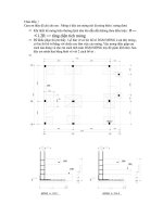
1.3 Power Pattern
A plot of the array response as a function of angle is referred to as array pattern or antenna
pattern. It is also called power pattern when the power response is plotted. It shows the
power received by the array at its output from a particular direction due to a unit power
source in that direction. A power pattern of an equispaced linear array of ten elements
with half-wavelength spacing is shown in Figure 1.1. The angle is measured with respect
to the line of the array. The beam-pointing direction makes a 90
°
angle with the line of
the array. The power pattern has been normalized by dividing the number of elements in
the array so that the maximum array gain in the beam-pointing direction is unity.
The power pattern drops to a low value on either side of the beam-pointing direction.
The place of the low value is normally referred to as a null. Strictly speaking, a null is a
position where the array response is zero. However, the term sometimes is misused to
indicate the low value of the pattern. The pattern between the two nulls on either side of
the beam-pointing direction is known as the main lobe (also called main beam or simply
beam). The width of the main beam between the two half-power points is called the half-
power beamwidth. A smaller beamwidth results from an array with a larger extent. The
extent of the array is known as the aperture of the array. Thus, the array aperture is the
distance between the two farthest elements in the array. For a linear array, the aperture is
equal to the distance between the elements on either side of the array.
1.4 Beam Steering
For a given array the beam may be pointed in different directions by mechanically moving
the array. This is known as mechanical steering. Beam steering can also be accomplished
© 2004 by CRC Press LLC
by appropriately delaying the signals before combining. The process is known as electronic
steering, and no mechanical movement occurs. For narrowband signals, the phase shifters
are used to change the phase of signals before combining.
The required delay may also be accomplished by inserting varying lengths of coaxial
cables between the antenna elements and the combiner. Changing the combinations of
various lengths of these cables leads to different pointing directions. Switching between
different combinations of beam-steering networks to point beams in different directions
is sometimes referred to as beam switching.
When processing is carried out digitally, the signals from various elements can be
sampled, stored, and summed after appropriate delays to form beams. The required delay
is provided by selecting samples from different elements such that the selected samples
are taken at different times. Each sample is delayed by an integer multiple of the sampling
interval; thus, a beam can only be pointed in selected directions when using this technique.
1.5 Degree of Freedom
The gain and phase applied to signals derived from each element may be thought of as
a single complex quantity, hereafter referred to as the weighting applied to the signals. If
there is only one element, no amount of weighting can change the pattern of that antenna.
However, with two elements, when changing the weighting of one element relative to the
other, the pattern may be adjusted to the desired value at one place, that is, you can place
one minima or maxima anywhere in the pattern. Similarly, with three elements, two
positions may be specified, and so on. Thus, with an L-element array, you can specify L – 1
positions. These may be one maxima in the direction of the desired signal and L – 2
minimas (nulls) in the directions of unwanted interferences. This flexibility of an L element
array to be able to fix the pattern at L – 1 places is known as the degree of freedom of the
array. For an equally spaced linear array, this is similar to an L – 1 degree polynomial of
L – 1 adjustable coefficients with the first coefficient having the value of unity.
FIGURE 1.1
Power pattern of a ten-element linear array with half-wavelength spacing.
0 20 40 60 80 100 120 140 160 180
10
8
10
6
10
4
10
2
10
0
Angle in degree
Power Response
Main Beam
Sidelobe
© 2004 by CRC Press LLC
1.6 Optimal Antenna
An antenna is optimal when the weight of each antenna element is adjusted to achieve
optimal performance of an array system in some sense. For example, assume that a
communication system is operating in the presence of unwanted interferences. Further-
more, the desired signal and interferences are operating at the same carrier frequency such
that these interferences cannot be eliminated by filtering. The optimal performance for a
communication system in such a situation may be to maximize the signal-to-noise ratio
(SNR) at the output of the system without causing any signal distortion. This would
require adjusting the antenna pattern to cancel these interferences with the main beam
pointed in the signal direction. Thus, the communication system is said to be employing
an optimal antenna when the gain and the phase of the signal induced on each element
are adjusted to achieve the maximum output SNR (sometimes also referred to as signal
to interference and noise ratio, SINR).
1.7 Adaptive Antenna
The term adaptive antenna is used for a phased array when the weighting on each element
is applied in a dynamic fashion. The amount of weighting on each channel is not fixed at
the time of the array design, but rather decided by the system at the time of processing
the signals to meet required objectives. In other words, the array pattern adapts to the
situation and the adaptive process is under control of the system. For example, consider
the situation of a communication system operating in the presence of a directional inter-
ference operating at the carrier frequency used by the desired signal, and the performance
measure is to maximize the output SNR. As discussed previously, the output SNR is
maximized by canceling the directional interference using optimal antennas. The antenna
pattern in this case has a main beam pointed in the desired signal direction, and has a null
in the direction of the interference. Assume that the interference is not stationary but moving
slowly. If optimal performance is to be maintained, the antenna pattern needs to adjust so
that the null position remains in the moving interference direction. A system using adaptive
antennas adjusts the weighting on each channel with an aim to achieve such a pattern.
For adaptive antennas, the conventional antenna pattern concepts of beam width, side
lobes, and main beams are not used, as the antenna weights are designed to achieve a set
performance criterion such as maximization of the output SNR. On the other hand, in
conventional phase-array design these characteristics are specified at the time of design.
1.8 Smart Antenna
The term smart antenna incorporates all situations in which a system is using an antenna
array and the antenna pattern is dynamically adjusted by the system as required. Thus,
a system employing smart antennas processes signals induced on a sensor array. A block
diagram of such a system is shown in Figure 1.2.
© 2004 by CRC Press LLC
The type of sensors used and the additional information supplied to the processor
depend on the application. For example, a communication system uses antennas as sensors
and may use some signal characteristics as additional information. The processor uses
this information to differentiate the desired signal from unwanted interference.
A block diagram of a narrowband communication system is shown in Figure 1.3 where
signals induced on an antenna array are multiplied by adjustable complex weights and
then combined to form the system output. The processor receives array signals, system
output, and direction of the desired signal as additional information. The processor cal-
culates the weights to be used for each channel.
1.9 Book Outline
Chapter 2 is dedicated to various narrowband processors and their performance. Adaptive
processing of narrowband signals is discussed in Chapter 3. Descriptions and analyses of
FIGURE 1.2
Block diagram of an antenna array system.
FIGURE 1.3
Block diagram of a communication system using an antenna array.
Sensor 1
Sensor 2
Sensor L
Processor
Output
Additional
Information
Antenna 1
Antenna 2
Antenna L
Weight
Estimation
Output
Desired
Signal
Direction
+
Weights
© 2004 by CRC Press LLC
broadband-signal processors are presented in Chapter 4. In Chapter 5, situations are
considered in which the desired signals and unwanted interference are not independent.
Chapter 6 is focused on using the received signals on an array to identify the direction of
a radiating source. Chapter 7 and Chapter 8 are focused on fading channels. Chapter 7
describes such channels and analyzes the performance of a single antenna system in a
fading environment. Chapter 8 considers multiple antenna systems and presents various
diversity-combining techniques.
References
App76 Applebaum, S.P., Adaptive arrays, IEEE Trans. Antennas Propagat., 24, 585–598, 1976.
Com88 Compton Jr., R.T., Adaptive Antennas: Concepts and Performances, Prentice Hall, New York,
1988.
d’A80 d’Assumpcao, H.A., Some new signal processors for array of sensors, IEEE Trans. Inf. Theory,
26, 441–453, 1980.
d’A84 d’Assumpcao, H.A. and Mountford, G.E., An overview of signal processing for arrays of
receivers, J. Inst. Eng. Aust. IREE Aust., 4, 6–19, 1984.
Gab76 Gabriel, W.F., Adaptive arrays: An introduction, IEEE Proc., 64, 239–272, 1976.
God97 Godara, L.C., Application of antenna arrays to mobile communications. Part I: Performance
improvement, feasibility and system considerations, Proc. IEEE, 85, 1031–1062, 1997.
God00 Godara, L.C., Ed., Handbook of Antennas in Wireless Communications, CRC Press, Boca Raton,
FL, 2002.
Hay85 Haykin, S., Ed., Array Signal Processing, Prentice Hall, New York, 1985.
Hay92 Haykin, S. et al., Some aspects of array signal processing, IEE Proc., 139, Part F, 1–19, 1992.
Hud81 Hudson, J.E., Adaptive Array Principles, Peter Peregrins, New York, 1981.
IEE64 IEEE, Special issue on active and adaptive antennas, IEEE Trans. Antennas Propagat., 12, 1964.
IEE76 IEEE, Special issue on adaptive antennas, IEEE Trans. Antennas Propagat., 24, 1976.
IEE85 IEEE, Special issue on beamforming, IEEE J. Oceanic Eng., 10, 1985.
IEE86 IEEE, Special issue on adaptive processing antenna systems, IEEE Trans. Antennas Propagat.,
34, 1986.
IEE87a IEEE, Special issue on adaptive systems and applications, IEEE Trans. Circuits Syst., 34, 1987.
IEE87b IEEE, Special issue on underwater acoustic signal processing, IEEE J. Oceanic Eng., 12, 1987.
Kri96 Krim, H. and Viberg, M., Two decades of array signal processing: the parametric approach,
IEEE Signal Process. Mag., 13(4), 67–94, 1996.
Mai82 Maillous, R.J., Phased array theory and technology, IEEE Proc., 70, 246–291, 1982.
Mar86 Marr, J.D., A selected bibliography on adaptive antenna arrays, IEEE Trans. Aerosp. Electron.
Syst., 22, 781–788, 1986.
Mon80 Monzingo, R. A. and Miller, T. W., Introduction to Adaptive Arrays, Wiley, New York, 1980.
Sch77 Schultheiss, P.M., Some lessons from array processing theory, in Aspects of Signal Processing,
Part 1, Tacconi, G., Ed., D. Reidel, Dordrecht, 1977, p. 309–331.
Sta74 Stark, L., Microwave theory of phased-array antennas: a review, IEEE Proc., 62, 1661–1701,
1974.
Van88 Van Veen, B.D. and Buckley, K.M., Beamforming: a versatile approach to spatial filtering,
IEEE ASSP Mag., 5, 4–24, 1988.
Wid67 Widrow, B. et al., Adaptive antenna systems, IEEE Proc., 55, 2143–2158, 1967.
Wid85 Widrow, B. and Stearns, S.D., Adaptive Signal Processing, Prentice Hall, New York, 1985.
© 2004 by CRC Press LLC
2
Narrowband Processing
2.1 Signal Model
2.1.1 Steering Vector Representation
2.1.2 Eigenvalue Decomposition
2.2 Conventional Beamformer
2.2.1 Source in Look Direction
2.2.2 Directional Interference
2.2.3 Random Noise Environment
2.2.4 Signal-to-Noise Ratio
2.3 Null Steering Beamformer
2.4 Optimal Beamformer
2.4.1 Unconstrained Beamformer
2.4.2 Constrained Beamformer
2.4.3 Output Signal-to-Noise Ratio and Array Gain
2.4.4 Special Case 1: Uncorrelated Noise Only
2.4.5 Special Case 2: One Directional Interference
2.5 Optimization Using Reference Signal
2.6 Beam Space Processing
2.6.1 Optimal Beam Space Processor
2.6.2 Generalized Side-Lobe Canceler
2.6.3 Postbeamformer Interference Canceler
2.6.3.1 Optimal PIC
2.6.3.2 PIC with Conventional Interference Beamformer
2.6.3.3 PIC with Orthogonal Interference Beamformer
2.6.3.4 PIC with Improved Interference Beamformer
2.6.3.5 Discussion and Comments
2.6.3.5.1 Signal Suppression
2.6.3.5.2 Residual Interference
2.6.3.5.3 Uncorrelated Noise Power
2.6.3.5.4 Signal-to-Noise Ratio
2.6.4 Comparison of Postbeamformer Interference Canceler with Element
Space Processor
2.6.5 Comparison in Presence of Look Direction Errors
2.7 Effect of Errors
2.7.1 Weight Vector Errors
2.7.1.1 Output Signal Power
2.7.1.2 Output Noise Power
2.7.1.3 Output SNR and Array Gain
2.7.2 Steering Vector Errors
2.7.2.1 Noise-Alone Matrix Inverse Processor
© 2004 by CRC Press LLC