Tài liệu Adaptive thu phát không dây P12 pdf
Bạn đang xem bản rút gọn của tài liệu. Xem và tải ngay bản đầy đủ của tài liệu tại đây (2 MB, 38 trang )
L121
Burst-by-Burst Adaptive
Multiuser Detection CDMA
E.
L.
Kuan and
L.
Hanzo'
12.1
Motivation
As argued throughout the previous chapters of the book, mobile propagation channels exhibit
time-variant propagation properties
[
131.
Although apart from simple cordless telephone
schemes most mobile radio systems employ power control for mitigating the effects of re-
ceived power fluctuations, rapid channel quality fluctuations cannot be compensated by prac-
tical, finite reaction-time power control schemes. Furthermore, the ubiquitous phenomenon
of signal dispersion due to the multiplicity of scattering and reflecting objects cannot be mit-
igated by power control. Similarly, other performance limiting factors, such as adjacent- and
co-channel intereference as well as multi-user interference vary as a function of time. The
ultimate channel quality metric is constituted by the bit error rate experienced, irrespective
of the specific impairment encountered. The channel quality variations
are
typically higher
near the fringes of the propagation cell or upon moving from an indoor scenario to an out-
door cell due to the high standard deviation of the shadow- and fast-fading
[
131
encountered,
even in conjunction with agile power control. Furthermore, the bit errors typically occur in
bursts due to the time-variant channel quality fluctuations and hence it is plausible that a fixed
transceiver mode cannot achieve a high flexibility in such environments.
The design of powerful and flexible transceivers has to be based on finding the best com-
promise amongst a number of contradicting design factors. Some of these contradicting fac-
tors are low power consumption, high robustness against transmission errors amongst various
channel conditions, high spectral efficiency, low-delay for the sake of supporting interactive
real-time multimedia services, high-capacity networking and
so
forth
[2].
In this chapter we
'This chapter is based
on
Kuan and Hanzo: Burst-by-Burst Adaptive Multiuser Detection CDMA:
A
Framework for Existing and Future Wireless Standards, submitted to the Proceedings
of
the IEEE OIEEE,
2001
497
Adaptive Wireless Tranceivers
L. Hanzo, C.H. Wong, M.S. Yee
Copyright © 2002 John Wiley & Sons Ltd
ISBNs: 0-470-84689-5 (Hardback); 0-470-84776-X (Electronic)
498
CHAPTER
12.
BURST-BY-BURST ADAPTIVE MULTIUSER DETECTION CDMA
will address a few of these issues in the context of Direct Sequence Code Division Multiple
Access (DS-CDMA) systems. It was argued in [2] that the time-variant optimization crite-
ria of a flexible multi-media system can only be met by
an
adaptive scheme, comprising the
firmware of a suite of system components and invoking that particular combination of speech
codecs, video codecs, embedded un-equal protection channel codecs, voice activity detector
(VAD) and transceivers, which fulfils the currently prevalent set of transceiver optimization
requirements.
These requirements lead to the concept of arbitrarily programmable, flexible so-called
software radios [322], which is virtually synonymous to the so-called tool-box concept in-
voked to a degree in
a
range
of
existing systems at the time of writing [3]. This concept
appears attractive also for third- and future fourth-generation wireless transceivers. A few
examples
of
such optimization criteria are maximising the teletraffic carried or the robustness
against channel errors, while in other cases minimization
of
the bandwidth occupancy or the
power consumption is of prime concern.
Motivated by these requirements in the context of the CDMA-based third-generation
wireless systems [13, 1461, the outline
of
the chapter is
as
follows. In Section 12.2 we re-
view the current state-of-the-art in multi-user detection with reference to the receiver family-
tree of Figure 12.4. Section 12.4 is dedicated to adaptive CDMA schemes, which endeavour
to guarantee a better performance than their fixed-mode counterparts. Burst-by-burst (BbB)
adaptive quadrature amplitude modulation (AQAM) based and Variable Spreading Factor
(VSF) assisted CDMA system proposals are studied comparatively in Section 12.5. Lastly
our conclusions are offered in Section 12.6.
12.2
Multiuser Detection
12.2.1
Single-User Channel Equalisers
12.2.1.1
Zero-Forcing Principle
The fundamental approach of multiuser equalisers accrues from recognising the fact that the
nature of the interference is similar, regardless, whether its source is dispersive multipath
propagation or multiuser interference. In other words, the effects of imposing interference on
the received signal by
a
K-path dispersive channel or by
a
K-user system are similar. Hence
below we continue our discourse with
a
rudimentary overview of single-user equalisers, in
order to pave the way for a more detailed discourse on multiuser equalisers.
The concept of zero-forcing (ZF) channel equalizers can be readily followed for exam-
ple using the approach of [89]. Specifically, the zero-forcing criterion [S91 constrains the
signal component at the output of the equalizer to be free of intersymbol interference
(ISI).
More explicitly, this implies that the product of the transfer functions of the dispersive and
hence frequency-selective channel and the channel equaliser results in a ’frequency-flat’ con-
stant, implying that the concatenated equaliser restores the perfect all-pass channel transfer
function. This can be formulated as:
G(z)
=
F(z)B(z)
=
1,
(12.1)
(12.2)
12.2.
MULTIUSER DETECTION
499
-1-
Channel
with
1
Zero-forcing
impulse response, Equalizer
n.
AWGN
bi
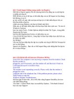
Figure
12.1:
Block diagram of a simple transmission scheme using
a
zero-forcing equalizer.
where
F(z)
and
B(z)
are
the z-transforms of the ZF-equaliser and of the dispersive channel,
respectively. The impulse response corresponding to the concatenated system hence becomes
a
Dirac delta, implying that no
IS1
is inflicted. More explicitly, the zero-forcing equalizer
is constituted by the inverse filter
of
the channel. Figure 12.1 shows the simplified block
diagram of the corresponding system.
Upon denoting by
D(z)
and
N(z)
the z-transforms of the transmitted signal and the
additive noise respectively, the z-transform
of
the received signal can be represented by
R(z),
where
R(z)
=
D(z)B(z)
+
N(z).
(12.3)
The z-transform of the multiuser equalizer’s output will be
6(z)
=
F(z)R(z)
(1
2.4)
(1
2.5)
(12.6)
From Equation 12.6, it can be seen that the output signal is free of
ISI.
However, the noise
component is enhanced by the inverse
of
the transfer function of the channel. This may
have
a
disastrous effect on the output of the equalizer, in terms of noise amplification in
the frequency domain at frequencies where the transfer function of the channel was severely
attenuated. Hence
a
disadvantage of the ZF-equaliser is that in an effort to compensate for
the effects of the dispersive and consequently frequency-selective channel and the associated
IS1
it substantially enhances the originally white noise spectrum by frequency-selectively
amplifying it. This deficiency can be mitigated by invoking the so-called minimum mean
square error linear equalizer, which is capable of jointly minimising the effects of noise and
interference, rather than amplifying the effects of noise.
12.2.1.2 Minimum Mean Square Error Equalizer
Minimum mean square error (MMSE) equalizers have been considered in depth for example
in
[89]
and
a
similar approach is followed here. Upon invoking the MMSE criterion
[89],
the
equalizer tap coefficients are calculated in order to minimize the MSE at the output of the
multiuser equalizer, where the MSE
is
defined
as
:
e:
=
E[/dl,
-
d^l,12],
(12.7)
500
CHAPTER
12.
BURST-BY-BURST ADAPTIVE MULTIUSER DETECTION CDMA
di
-I.(.~~~*~~~
F(z)
*
$i
Channel
with
1
MMSE
impulse response,
Equalizer
bi
"'i
AWGN
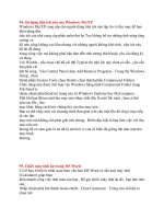
Figure 12.2:
Block diagram
of
a
simple transmission scheme employing an
MMSE
equalizer.
A
Feedforward
filter
Feedback filter
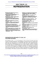
Figure
12.3:
Block diagram of
a
decision feedback equalizer.
where the function
E[z]
indicates the expected value of
2.
Figure 12.2 shows the system's
schematic using an MMSE equalizer, where
B(z)
is the channel's transfer function and
F(z)
is the transfer function of the equalizer. The output of the equalizer is given by
:
8(z)
=
F(z)B(z)D(z)
+
F(z)lL'(z);
(12.8)
where
D(
z)
is the z-transform of the data bits
d,,
fi(
z)
is the z-transform of the data estimates
&
and
N(z)
is the z-transform of the noise samples
11%.
12.2.1.3
Decision Feedback Equalizers
The decision feedback equalizer (DFE) [89] can be separated into two components,
a
feed-
forward filter and
a
feedback filter. The schematic of a general DFE is depicted in Figure 12.3.
The philosophy of the DFE is two-fold. Firstly, it aims for reducing the filter-order of the ZFE,
since with the aid of Equation 12.2 and Figure 12.1 it becomes plausible that the inverse filter
of the channel,
B-'(z),
can only be implemented
as
an Infinite Impulse Response (IIR)
filter, requiring a high implementational complexity. Secondly, provided that there are no
transmission errors, the output of the hard-decision detector delivers the transmitted data bits,
which can provide valuable explicit training data for the DFE. Hence
a
reduced-length feed-
forward filter can be used, which however does not entirely eliminate the
ISI.
Instead, the
feedback filter uses the data estimates at the output
of
the data detector in order to subtract
the IS1 from the output
of
the feed-forward filter, such that the input signal of the data detector
has less
ISI,
than the signal at the output of the feed-forward filter. If it is assumed that the
data estimates fed into the feedback filter are correct, then the DFE is superior to the linear
equalizers, since the noise enhancement is reduced. One way of explaining this would be
to
say
that if the data estimates are correct, then the noise has been eliminated and there is
12.3.
MULTIUSER EQUALISER CONCEPTS
501
CDMA, receivers
Multiuser Single user
,
1
Adaptwe Non-adaptive
~~~ ~~~~
Decirrelator
Jb
1
I
L
~~
Tree-search Iterative Conventlonal Bhnd
LMMSE
l
,
LMS ZF-BLE
RLS
SIC M-algorithm
ZF-BDFE PIC T-algorithm
EKF "SE-BLE Hvhrid IC
Matched filter PSP-type
RAKE Stochastic gradient
Subspace tracking
"SE-BDFE
"
Figure
12.4:
Classification
of
CDMA
detectors.
no
noise enhancement in the feedback loop. However, if the data estimates are incorrect,
these errors will propagate through to future decisions and this problem is known as error
propagation.
There are two basic DFEs, the ZF-DFE and the MMSE-DE. Analogous to its linear
counterpart, the coefficients of the feedback filter for the ZF-DFE are calculated
so
that the
IS1 at the output of the feed-forward filter is eliminated and the input signal of the data
detector is free of IS1 [76]. Let us now focus our attention on CDMA multiuser detection
equalizers.
12.3 Multiuser Equaliser Concepts
DS-CDMA systems [323,324] support a multiplicity of users within the same bandwidth by
assigning different
-
typically unique
-
codes to different users for their communications, in
order to be able to distinguish their signals from each other. When the transmitted signal is
subjected to hostile wireless propagation environments, the signals of different users interfere
with each other and hence CDMA systems are interference-limited due to the multiple access
interference (MAI) generated by the users transmitting within the same bandwidth simulta-
neously. The subject of this chapter is, how the MA1 can be mitigated. A whole range of
detectors have been proposed in the literature, which will be reviewed with reference to the
family-tree of Figure 12.4 during our forthcoming discourse.
The conventional so-called single-user CDMA detectors of Figure 12.4
-
such as the
matched filter [280,325] and the RAKE combiner [76] -are optimized for detecting the signal
of a single desired user. RAKE combiners exploit the inherent multi-path diversity in CDMA,
since they essentially consist of matched filters for each resolvable path of the multipath
channel. The outputs of these matched filters
are
then coherently combined according to a
diversity combining technique, such as maximal ratio combining, equal gain combining or
selection diversity combining [76]. These conventional single-user detectors
are
inefficient,
since the interference is treated as noise and the knowledge of the channel impulse response
(CIR)
or
the spreading sequences of the interferers is not exploited.
In order to mitigate the problem of MAI, Verdu [326] proposed and analysed the opti-
mum multiuser detector for asynchronous Gaussian multiple access channels. The optimum
detector invokes all the possible bit sequences, in order to find the sequence that maximizes
502
CHAPTER
12.
BURST-BY-BURST ADAPTIVE MULTIUSER DETECTION CDMA
the correlation metric given by [225]
:
O(r;
d)
=
2dTr
-
dTRd,
(1
2.9)
where the elements of the vector
r
represent the cross-correlation of the spread, channel-
impaired received signal with each of the users’ spreading sequence, the vector
d
consists
of the bits transmitted by all the users during the current signalling instant and the matrix
R
is the cross-correlation (CCL) matrix of the spreading sequences. This optimum detec-
tor significantly outperforms the conventional single-user detector and
-
in contrast to sin-
gle user detectors
-
it is insensitive to power control errors, which is often termed as being
near-far resistant. However, unfortunately its complexity grows exponentially in the order
of
0(2NK),
where
N
is the number of overlapping asynchronous bits considered in the de-
tector’s decision window and
K
is the number of interfering users. In order to reduce the
complexity of the receiver and yet to provide an acceptable Bit Error Rate (BER) perfor-
mance, significant research efforts have been invested in the field of sub-optimal CDMA
multiuser receivers [225]. Multiuser detection exploits the base station’s knowledge of the
spreading sequences and that of the estimated (CIRs) in order to remove the MAL These
multiuser detectors can be categorized in a number of ways, such as linear versus non-linear,
adaptive versus non-adaptive algorithms or burst transmission versus continuous transmission
regimes. Excellent summaries
of
some of these sub-optimum detectors can be found in the
monographs by Veni [225], Prasad [327], Glisic and Vucetic [328]. Other MAI-mitigating
techniques include the employment of adaptive antenna arrays, which mitigate the level
of
MA1 at the receiver by forming a beam in the direction of the wanted user and a null towards
the interfering users. Research efforts invested in this area include, amongst others, the inves-
tigations carried out by Thompson, Grant and Mulgrew [329,330]; Naguib and Paulraj [33
l];
Godara [332]; as well as Kohno, Imai, Hatori and Pasupathy [333]. However, the area of
adaptive antenna arrays is beyond the scope of this article and the reader is referred to the
references cited for further discussions. In the forthcoming section, a brief survey of the
sub-optimal multiuser receivers will be presented with reference to Figure 12.4, which con-
stitutes an attractive compromise in terms of the achievable performance and the associated
complexity.
12.3.1
Linear Receivers
Following the seminal work by Verdli [326], numerous sub-optimum multiuser detectors have
been proposed for a variety of channels, data modulation schemes and transmission formats
[334]. These CDMA detector schemes will be classified with reference to Figure 12.4, which
will be referred to throughout our discussions. Lupas and Verdd [335] initially suggested a
sub-optimum linear detector for symbol-synchronous transmissions and further developed it
for asynchronous transmissions in a Gaussian channel [336]. This linear detector inverted the
CCL matrix
R
seen in Equation 12.9, which was constructed from the CCLs of the spreading
codes of the users and this receiver was termed the decorrelating detector. It was shown that
this decorrelator exhibited the same degree of near-far resistance, as the optimum multiuser
detector. A further sub-optimum multiuser detector investigated was the minimum mean
square error (MMSE) detector, where a biased version of the CCL matrix was inverted and
invoked, in order to optimize the receiver obeying the MMSE criterion.
123.
MULTIUSER EQUALISER CONCEPTS
503
Zvonar and Brady [337] proposed a multiuser detector for synchronous CDMA systems
designed for a frequency-selective Rayleigh fading channel. Their approach also used a bank
of matched filters followed by a so-called whitening filter, but maximal ratio combining was
used to combine the resulting signals. The decorrelating detector of [336] was further devel-
oped for differentially-encoded coherent multiuser detection in flat fading channels by Zvonar
et
al.
[338]. Zvonar also amalgamated the decorrelating detector with diversity combining,
in order to achieve performance improvements in frequency selective fading channels [339].
A multiuser detector jointly performing decorrelating CIR estimation and data detection was
investigated by Kawahara and Matsumoto [340]. Path-by-path decorrelators were employed
for each user in order to obtain the input signals required for CIR estimation and the CIR
estimates as well as the outputs of a matched filter bank were fed into
a
decorrelator for de-
modulating the data. A variant of this idea was also presented by Hosseinian, Fattouche and
Sesay [341], where training sequences and a decorrelating scheme were used for determin-
ing the CIR estimate matrix. This matrix was then used in a decorrelating decision feedback
scheme for obtaining the data estimates. Juntti, Aazhang and Lilleberg [342] proposed iter-
ative schemes, in order to reduce the complexity. Sung and Chen [343] advocated using a
sequential estimator for minimizing the mean square estimation error between the received
signal and the signal after detection. The cross-correlations between the users’ spreading
codes and the estimates of the channel-impaired received signal of each user were needed, in
order to obtain estimates of the transmitted data for each user. Duel-Hallen [344] proposed
a decorrelating decision-feedback detector for removing the MA1 from a synchronous sys-
tem communicating over a Gaussian channel. The outputs from a bank of filters matched
to the spreading codes of the users were passed through a whitening filter. This filter was
obtained by decomposing the CCL matrix of the users’ spreading codes with the aid of the
Cholesky decomposition [233] technique. The results showed that MA1 could be removed
from each user’s signal successively, assuming that there was
no
error propagation. However,
estimates of the received signal strengths of the users were needed, since the users had to be
ranked in order of decreasing signal strengths
so
that the more reliable estimates were ob-
tained first. Duel-Hallen’s decorrelating decision feedback detector [344] was improved by
Wei and Schlegel [345] with the aid of a sub-optimum variant of the Viterbi algorithm, where
the most likely paths were retained in the case of merging paths in the Viterbi algorithm.
The decorrelating decision feedback detector [344] was also improved with the assistance of
soft-decision convolutional coding by Hafeez and Stark [346]. Soft decisions from a Viterbi
channel decoder were fed back into the filter for signal cancellation.
Having reviewed the range of linear receivers, let us now consider the class of joint de-
tection schemes, which can be found
in
the family-tree of Figure 12.4 in the next section.
12.3.2
Joint Detection
12.3.2.1
Joint Detection Concept
As mentioned before in the context of single-user channel equalization, the effect of MA1
on the desired signal is similar to the impact of multipath propagation-induced Inter-symbol
Interference (ISI) on the same signal. Each user in a K-user system suffers from MA1 due to
the other
(K
-
1)
users. This MA1 can also be viewed as a single-user signal perturbed by IS1
inflicted by
(K
-
1)
paths in a multipath channel. Therefore, classic equalization techniques
504
CHAPTER
12.
BURST-BY-BURST ADAPTIVE MULTIUSER DETECTION CDMA
[76,103,118,280] used to mitigate the effects of
IS1
can be modified for multiuser detection
and these types of multiuser detectors can be classified as joint detection receivers. The joint
detection
(JD)
receivers were developed for burst-based, rather than continuous transmission.
The concept of joint detection for the uplink was proposed by Klein and Baier [226] for
synchronous burst transmissions, which is visualised with the aid of Figure
12.5.
In Figure 12.5 there are a total of
K
users in the system, where the information is trans-
mitted in bursts. Each user transmits
N
data symbols per burst and the data vector for user
k
is represented as
d(k).
Each data symbol is spread with
a
user-specific spreading sequence,
dk),
which has a length of Q chips. In the uplink, the signal of each user passes through a
different mobile channel characterized by its time-varying complex impulse response,
h(k).
By sampling at the chip rate of l/Tc, the impulse response can be represented by
W
complex
samples. Following the approach of Klein
et
al.
[226], the received burst can be represented
as
y
=
Ad
+
n,
where
y
is the received vector and consists of the synchronous sum of the
transmitted signals of all the
K
users, corrupted by a noise sequence,
n.
The matrix
A
is
referred to as the system matrix and it defines the system's response, representing the effects
of MA1 and the mobile channels. Each column in the matrix represents the combined impulse
response obtained by convolving the spreading sequence
of
a
user with its channel impulse
response,
b(k)
=
dk)
*
h(k).
This is the impulse response experienced by a transmitted data
symbol. Upon neglecting the effects of the noise the joint detection formulation
is
simply
based on inverting the system matrix
A,
in order to recover the data vector constituted by
the superimposed transmitted information of all the
K
CDMA users. The dimensions of the
matrix
A
are (NQ
+
W
-
1)
x
KN
and an example
of
it can be found in reference [226] by
Klein
et
al,
where the list of the symbols used is given as
:
0
K
for the total number of users,
0
N
is the number of data symbols transmitted by each user in one transmission burst,
0
Q
represents the number
of
chips in each spreading sequence,
0
W
denotes the length of the wideband CIR, where
W
is assumed to be an integer
multiple of the number of chip intervals,
T,.
0
L
indicates the number of multipath components or taps in the wideband CIR.
In order to introduce compact mathematical expressions, matrix notation will be em-
ployed. The transmitted data symbol sequence
of
the k-th user is represented by a vector
as:
=
(dl"),
dp),
.
.
. ,
. . .
,
&))T,
(12.10)
fork=l,
,
K;
n=l,
,N,
where
IC
is the user index and
n
is the symbol index. There are
N
data symbols per transmis-
sion burst and each data symbol is generated using an
m-ary
modulation scheme [76].
The Q-chip spreading sequence vector of the k-th user is expressed as
:
123.
MULTIUSER EOUALISER CONCEPTS
505
mobile radio
channel
1,
h("
mobile radio
channel
2,
h(2)
t
I
I
~
spreading code
2,
c
(2)
I
m
m
m
m
mobile radio
channel
K,
h(K)
l
spreading code
K,
c
(K)
n
interference
and noise
t
joint
detection
data
estimator
Figure
12.5:
System model
of
a synchronous
CDMA
system on the up-link using joint detection.
The CIR for the
n-th
data symbol of the Ic-th user is represented as
hik)
=
(@)(l),
.
.
.
,
hik)(w),
. . . ,
f~i~)(W))~,
fork
=
1,.
.
.
,K;
W
=
1,.
.
.
,W,
(12.12)
consisting of
W
complex CIR samples
hik)(w)
taken at the chip rate of
l/Tc.
defined by the convolution of
c(')
and
h,
(k)
,
which is represented as
:
The combined impulse response,
bhk),
due to the spreading sequence and the CIR
is
In order
to
represent the IS1 due to the
N
symbols and the dispersive combined impulse
responses, the discretised received signal,
dk),
of user
k
can be expressed as the product of a
matrix
A(k)
and its data vector
d('"),
where
:
506
CHAPTER
12.
BURST-BY-BURST ADAPTIVE MULTIUSER DETECTION CDMA
The i-th element of the received signal vector
dk)
is
:
N
rjk)
=
x[A(")]indF),
fori
=
1,.
.
. ,
NQ
+
W
-
1.
(12.15)
n=
1
Again, the matrix
A(k)
is the so-called system matrix of the k-th user and it is constructed
from the combined impulse responses of Equation 12.13. It represents the effect of the com-
bined impulse responses on each data symbol
dik)
in the data vector,
d(").
Each column
in the matrix
A
indexed by
n
contains the combined impulse response,
bik)
that affects the
n-th symbol of the data vector. However, since the data symbols are spread by the Q-chip
spreading sequences, they are transmitted Q chips apart from each other. Hence the start of
the combined impulse response,
bik),
for each column is offset by
Q
rows from the start
of
bfll
in the preceding column. Therefore, the element in the
[(n
-
1)Q
+
l]-th row and
the n-th column of
A(k)
is the I-th element of the combined impulse response,
bp),
for
1
=
1,
. . .
,
Q
+
W
-
1.
All other elements in the column are zero-valued.
The pictorial representation of Equation 12.14 is shown in Figure 12.6, where
Q
=
4,
W
=
2 and
N
=
3. As it can be seen from the diagram, in each column of the matrix
A(k)
-
where a box with an asterisk marks a non-zero element
-
the vector
bik)
starts at an offset
of
Q
=
4
rows below its preceding column, except for the first column, which starts at the
first row. The total number of elements in the vector
bik)
is
(Q
+
W
-
1)
=
5.
The total
number
of
columns in the matrix
A(k)
equals the number of symbols in the data vector,
d('"),
i.e.
N.
Finally, the received signal vector product,
dk)
in Equation 12.14, has a total of
(NQ
+
W
-
1)
=
13
elements due to the
IS1
imposed by the multipath channel, as opposed
to
NQ
=
12 elements in a narrowband channel.
The joint detection receiver aims for detecting the symbols of all the users jointly by
utilizing the information available on the spreading sequences and
CIR
estimates of all the
users. Therefore, as seen in Figure 12.7, the data symbols of all
K
users can be viewed as
the transmitted data sequence of a single user, by concatenating all the data sequences. The
overall transmitted sequence can be rewritten as
:
d
=
(d('jT, d(2)T,.
.
. ,
d(K)T)T
(12.16)
=
(dl,
d2,.
.
.
,
(12.17)
whered,=dik)forj=n+N.(k-1),k=1,2
,
,Kandn=1,2
,
,N.
of each
of
the
K
users column-wise, whereby
:
The system matrix for the overall system can be constructed by appending the
A(k)
matrix
A
=
(A(1), A('),
.
.
.
,A(",
.
. .
,
A(K)).
(12.18)
The construction of matrix
A
from the system matrices
of
the
K
users is depicted
in
Figure
12.7. Therefore, the discretised received composite signal can be represented in matrix form
as
:
12.3.
MULTIUSER EQUALISER CONCEPTS
507
\a
A
!Q
0
A
iQ
0
Figure
12.6:
Stylized structure of Equation 12.14 representing the received signal vector
of
a wideband
channel, where
Q
=
4,
W
=
2
and
N
=
3.
The column vectors in the matrix
ACk)
are
the combined impulse response vectors,
bhk)
of Equation 12.13.
A
box with
an
asterisk in
it represents a non-zero element, and the remaining notation is as follows
:
K
represents
the total number of users,
N
denotes the number
of
data symbols transmitted by each user,
Q
represents the number
of
chips in each spreading sequence, and
W
indicates the length
of
the wideband
CIR.
Figure
12.7:
The construction
of
matrix
A
from the individual system matrices,
A(k)
seen in Figure
12.6, and the data vector
d
from the concatenation of data vectors,
d(')),
of
all
K
users.
where
n
=
(721,
n2,.
.
.
,
n~~+w-l)~,
is the noise sequence, which has
a
covariance matrix
of
R,
=
E[n.nH].
The composite signal vector
y
has
(NQ
+
W
-
1)
elements for
a
data
burst
of
length
N
symbols. Upon multiplying the matrix
A
with the vector
d
seen in Figure
12.7, we obtain the MAI- and ISI-contaminated received symbols according to Equation
12.19.
Taken
as
a
whole, the system matrix,
A,
can be constructed from the combined response
508
CHAPTER
12.
BURST-BY-BURST ADAPTIVE MULTIUSER DETECTION CDMA
vectors,
bik)
of all the
K
users, in order to depict the effect of the system's response on the
data vector of Equation 12.16. The dimensions of the matrix
are
(NQ
+
W
-
1)
x
KN.
Figure 12.8 shows an example of the matrix,
A,
for an N-bit long data burst. For ease of
representation, we assumed that the channel length,
W,
for each user is the same and that
it remains constant throughout the data burst. We have also assumed that the channel expe-
riences slow fading and that the fading is almost constant across the data burst. Therefore,
the combined response vector for each transmitted symbol of user
IC
is represented by
b(')),
where
b(k)
=
by)bF)
=
.
. .
=
bc).
Focusing our attention on Figure 12.8, the elements
in the j-th column of the matrix constitute the combined response vector that affects the j-th
data symbol in the transmitted data vector
d.
Therefore, columns
j
=
1
to
N
of matrix
A
correspond to symbols
m
=
1
to
N
of vector
d,
which
are
also the data symbols of user
k
=
1.
The next
N
columns correspond to the next
N
symbols of data vector
d,
which are
the data symbols of user
IC
=
2
and
so
on.
For user
IC,
each successive response vector,
b("),
is placed at an offset of
Q
rows from
the preceding vector, as shown in Figure 12.8. For example, the combined response vector
in column
1
of matrix
A
is
b(l)
and it starts at row
1
of the matrix because that column
corresponds to the first symbol of user
IC
=
1.
In column 2, the combined response vector is
also
b('),
but it is offset from the start of the vector in column
1
by
Q
rows. This is because
the data symbol corresponding to this matrix column is transmitted
Q
chips later. This is
repeated until the columns
j
=
I,
. .
.
,
N
contain the combined response vectors that affect
all the data symbols of user
k
=
1.
The next column of
j
=
N
+
1
in the matrix
A
contains
the combined impulse response vector that affects the data symbol,
d~+1
=
dy),
which is
the first data symbol of user
IC
=
2.
In this column, the combined response vector for user
IC
=
2,
b('),
is used and the vector starts at row
1
of the matrix because it is the first symbol
of this user. The response matrix,
b(')
is then placed into columns
j
=
N
+
1,
. . .
,2N
of the
matrix
A,
with the same offsets for each successive vector, as was carried out for user
1.
This
process is repeated for all the other users until the system matrix is completely constructed.
The mathematical representation of matrix
A
in general can be written as
:
{
o(k)
b,
(1)
for
IC
=
I,.
.
.
,K;
n
=
1,.
.
.
,
N;
[A]ij
=
1=1,
,&+W-l
(12.20)
otherwise,
fori=l,
,
NQ+W-1,
j=l,
,
KN,
where
i
=
Q(n
-
1)
+
l
and
j
=
n
+
N(k
-
1).
Figure 12.9 shows the stylized structure of Equation 12.19 for a specific example. In the
figure, a system with
K
=
2
users is depicted. Each user transmits
N
=
3
symbols per
transmission burst, and each symbol is spread with a signature sequence of length
Q
=
3
chips. The channel for each user has
a
dispersion length of
W
=
3
chips. The blocked
segments in the figure represent the combination
of
elements that result in the element
y4,
which is obtained from Equation 12.19 by
:
KN=6
Y4
=
C
[A]4,idi
+
n4
(12.21)
i=l
=
[A]4,ldl
+
[A]4,2&
+
[A]4,4d4
+
[A]4,5&
+
n4
(12.22)
123.
MULTIUSER EOUALISER
CONCEPTS
509
Figure
12.8:
Stylized structure of the system matrix
A,
where
b('), b(2)
and
b(K)
are column vectors
representing the combined impulse responses
of
users
1,2
and
K,
respectively in Equation
12.13.
The notation is
as
follows
:
K
represents the total number
of
users,
N
denotes the
number
of
data symbols transmitted by each user,
Q
represents the number
of
chips in
each spreading sequence, and
W
indicates the length
of
the wideband
CIR.
<
P<
P
k=l k=2
0
A
System matrix
A
V
V
d
k=
l
k=2
+
+
n
Y
Data
Noise
Received
vector
vector
vector
Figure
12.9:
Stylized structure
of
the matrix equation
y
=
Ad
+
n
for
a
K
=
2-user system. Each
user transmits
N
=
3
symbols per transmission burst, and each symbol is spread with
a
signature sequence of length
Q
=
3
chips. The channel
for
each user
has
a
dispersion
length
of
W
=
3
chips.
510
CHAPTER
12.
BURST-BY-BURST ADAPTIVE MULTIUSER DETECTION CDMA
Figure
12.10:
Structure
of
the receiver represented
in
Equation
12.23.
Given the above transmission regime, the basic concept of joint detection is centred
around processing the received composite signal vector,
y,
in order to determine the trans-
mitted data vector,
d.
This concept is encapsulated in the following set of equations
:
9
=
Sd
=
My,
(12.23)
where
S
is a square matrix with dimensions
(KN
x
KN)
and the matrix
M
is a
[KN
x
(NQ
+
W
-
l)]-matrix. These two matrices determine the type of joint detection algorithm,
as it will become explicit during our further discourse. The schematic in Figure 12.10 shows
the receiver structure represented by this equation.
A range of joint detection schemes designed for uplink communications were proposed
by Jung, Blanz, Nasshan, Steil, Baier and Klein, such as the minimum mean-square error
block linear equalizer ("SE-BLE) [208,219,227,228], the zero-forcing block decision
feedback equalizer (ZF-BDFE) [219,228] and the minimum mean-square error block deci-
sion feedback equalizer ("SE-BDFE) [219,228].
These joint-detection receivers were also combined with coherent receiver antenna diver-
sity (CRAD) techniques [219,227,228,347] and turbo coding [348,349] for performance im-
provement. Joint detection receivers were proposed also for downlink scenarios by Nasshan,
Steil, Klein and Jung [350,35 l]. CIR estimates were required for the joint detection receivers
and CIR estimation algorithms were proposed by Steiner and Jung [352] for employment
in
conjunction with joint detection. Werner [353] extended the joint detection receiver by com-
bining ZF-BLE and "SE-BLE techniques with a multistage decision mechanism using
soft inputs to a Viterbi decoder.
Having considered the family of JD receivers, which typically exhibit a high complex-
ity, let us now highlight the state-of-the-art
in
the context of lower complexity interference
cancellation schemes
in
the next section.
12.3.3
Interference Cancellation
Interference cancellation (IC) schemes constitute another variant of multiuser detection and
they can be broadly divided into three categories, parallel interference cancellation (PIC),
successive interference cancellation (SIC) and the hybrids of both, as seen
in
Figure 12.4.
Varanasi and Aazhang [354] proposed a multistage detector for an asynchronous system,
where the outputs from a matched filter bank were fed into a detector that performed MA1
cancellation using a multistage algorithm. At each stage in the detector, the data estimates
d('),
. .
.
,
d(K-l)
of all the other
(K
-
1)
users from the previous stage were used for recon-
structing an estimate of the MA1 and this estimate was then subtracted from the interfered
received signal representing the wanted bit. The computational complexity of this detector
was linear
with
respect to the number of users,
K.
Figure
12.1
1
depicts the schematic of
12.3.
MULTIUSER EOUALISER CONCEPTS
511
Figure
12.11:
Schematic
of
a single cancellation stage for user
IC
in the parallel interference cancel-
lation
(PIC)
receiver
for
K
users. The data estimates,
d('),
. . .
,
d(K-l)
of
the other
(K
-
1)
users were obtained from the previous cancellation stage and the received sig-
nal of each user other
than
the k-th one is reconstructed and cancelled from the received
signal,
r.
a single cancellation stage in the PIC receiver. Varanasi further modified the above paral-
lel cancellation scheme, in order to create a parallel group detection scheme for Gaussian
channels [355] and later developed it further for frequency-selective slow Rayleigh fading
channels [356]. In this scheme,
K
users were divided into
P
groups and each group was de-
modulated in parallel using a group detector. Yoon, Kohno and Imai [357] then extended the
applicability of the multistage interference cancellation detector to a multipath, slowly fading
channel. At each cancellation stage, hard decisions generated by the previous cancellation
stage were used for reconstructing the signal of each user and for cancelling its contribution
from the composite signal. The effects
of
CIR estimation errors on the performance of the
cancellation scheme were also considered. A multiuser receiver that integrated MA1 rejec-
tion and channel decoding was investigated by Giallorenzi and Wilson [358]. The MA1 was
cancelled via a multistage cancellation scheme and soft-outputs were fed from the Viterbi
channel decoder of each user to each stage for improving the performance.
The PIC receiver of Figure
12.1
l
[354] was also modified for employment in multi-carrier
modulation [359] by Sanada and Nakagawa. Specifically, convolutional coding was used in
order to obtain improved estimates
of
the data for each user at the initial stage and these
estimates were then utilized for interference cancellation in the following stages. The em-
ployment of convolutional coding improved the performance by
1.5
dB.
Latva-aho, Juntti
and Heikkila [360] enhanced the performance of the parallel interference cancellation re-
512 CHAPTER 12. BURST-BY-BURST ADAPTIVE MULTIUSER DETECTION CDMA
m m
m m
-1
Demodulator
I I
Figure
12.12:
Schematic
of
the successive interference cancellation
(SIC)
receiver for
K
users. The
users' signals have been ranked, where user
1
'S
signal was received at the highest power,
while user
K's
signal at the lowest power. In
the
order
of
ranking, the data estimates
of
each user are obtained and the received signal
of
each user is reconstructed and cancelled
from the received composite signal,
r.
ceiver by feeding back CIR estimates to the signal reconstruction stage
of
the multistage
receiver seen in Figure 12.11 and proposed an algorithm for mitigating error propagation.
Dahlhaus, Jarosch, Fleury and Heddergott [361] combined multistage detection with CIR
estimation techniques utilizing the outputs
of
antenna arrays. The CIR estimates obtained
were fed back into the multistage detector in order to refine the data estimates. An advanced
parallel cancellation receiver was also proposed by Divsalar, Simon and Raphaeli [362]. At
each cancellation stage, only partial cancellation was carried out by weighting the regener-
ated signals with
a
less than unity scaling factor. At each consecutive stage, the weights were
increased based on the assumption that the estimates became increasingly accurate.
Following the above brief notes on PIC receivers, let
us
now consider the family of
reduced-complexity
SIC
receivers classified in Figure
12.4.
A simple SIC scheme was anal-
ysed by Pate1 and Holtzman [363].
The
received signals were ranked according to their
correlation values, which were obtained by utilizing the correlations between the received
signal and the spreading codes
of
the users. The transmitted information of the strongest user
was estimated, enabling the transmitted signal to be reconstructed with the aid
of
the spreader
as well as the CIR and subtracted from the received signal, as portrated in Figure
12.12.
This
12.3.
MULTIUSER EQUALISER CONCEPTS
513
was repeated for the next strongest user, where the reconstructed signal of this second user
was cancelled from the composite signal remaining after the first cancellation. The interfer-
ence cancellation was carried out successively for all the other users, until eventually only the
signal of the weakest user remained. It was shown that the SIC receiver improved the BER
and the system’s user capacity over that of the conventional matched filter for the Gaussian,
for narrowband Rayleigh and for dispersive Rayleigh channels. Multipath diversity was also
exploited by combining the SIC receiver with the RAKE correlator [363]. Again, Figure
12.12 shows the schematic of the SIC receiver. Soong and Krzymien [364] extended the SIC
receiver by using reference symbols in order to aid the CIR estimation. The performance
of the receiver was investigated in flat and frequency-selective Rayleigh fading channels, as
well as in multi-cell scenarios. A soft-decision based adaptive SIC scheme was proposed by
Hui and Letaief [365], where soft decisions were used in the cancellation stage and if the
decision statistic did not satisfy a certain threshold, no data estimation was carried out for
that particular data bit, in order to reduce error propagation.
Hybrid
SIC
and
PIC
schemes were proposed by Oon, Li and Steele [366,367], where
SIC was first performed
on
the received signal, followed by a multistage PIC arrangement.
This work was then extended to an adaptive hybrid scheme for flat Rayleigh fading chan-
nels [368].
In
this scheme, successive cancellation was performed for a fraction of the users,
while the remaining users’ signals were processed via a parallel cancellation stage. Finally,
multistage parallel cancellation was invoked. The number of serial and parallel cancellations
performed was varied adaptively according to the BER estimates. Sawahashi, Miki, Andoh
and Higuchi [369] proposed a pilot symbol-assisted multistage hybrid successive-parallel
cancellation scheme. At each stage, data estimation was carried out successively for all the
users, commencing with the user having the strongest signal and ending with the weakest
signal. For each user, the interference inflicted by the other users was regenerated using the
estimates of the current stage for the stronger users and the estimates of the previous stage
for the weaker users. CIR estimates were obtained for each user by employing pilot symbols
and a recursive estimation algorithm. Another hybrid successive and parallel interference
cancellation receiver was proposed by Sun, Rasmussen, Sugimoto and Lim [370], where the
users to be detected were split into a number of groups. Within each group, PIC was per-
formed on the signals of these users belonging to the group. Between the separate groups,
SIC was employed. This had the advantage of a reduced delay and improved performance
compared to the SIC receiver. A further variant of the hybrid cancellation scheme was con-
stituted by the combination of MMSE detectors with SIC receivers, as proposed by Cho and
Lee [371]. Single-user MMSE detectors were used to obtain estimates of the data symbols,
which were then fed back into the
SIC
stages. An adaptive interference cancellation scheme
was investigated by Agashe and Woerner [372] for a multicellular scenario, where interfer-
ence cancellation was performed for both in-cell interferers and out-of-cell interferers. It was
shown that cancelling the estimated interference from users having weak signals actually de-
graded the performance, since the estimates were inaccurate. The adaptive scheme exercised
interference cancellation in
a
discriminating manner, using only the data estimates of users
having strong received signals. Therefore signal power estimation was needed and the thresh-
old for signal cancellation was adapted accordingly. Following the above brief discourse on
interference cancellation algorithms, let us now focus our attention on the tree-type detection
techniques, which were also categorized in Figure 12.4.
514
CHAPTER
12.
BURST-BY-BURST ADAPTIVE MULTIUSER DETECTION CDMA
12.3.4
Tree-Search Detection
Several tree-search detection [373-3751 receivers have been proposed in the literature, in
order to reduce the complexity of the original maximum likelihood detection scheme pro-
posed by Verdli [326]. Specifically, Rasmussen, Lim and Aulin [373] investigated a tree-
search detection algorithm, where a recursive, additive metric was developed in order to
reduce the search complexity. Reduced tree-search algorithms, such as the well-known M-
algorithms [376] and T-algorithms [376] were used by Wei, Rasmussen and Wyrwas [374]
in order to reduce the complexity incurred by the optimum multiuser detector. According
to the M-algorithm, at every node of the trellis search algorithm, only
M
surviving paths
were retained, depending
on
certain criteria such as for example the highest-metric
hl
num-
ber of paths. Alternatively, all the paths that were within a fixed threshold,
T,
compared
to the highest metric were retained. At the decision node, the path having the highest met-
ric was chosen as the most likely transmitted sequence. Maximal-ratio combining was also
used in conjunction with the reduced tree-search algorithms and the combining detectors out-
performed the “non-combining’’ detectors. The T-algorithm was combined with soft-input
assisted Viterbi detectors for channel-coded CDMA multiuser detection in the work carried
out by Nasiri-Kenari, Sylvester and Rushforth [375]. The recursive tree-search detector gen-
erated soft-outputs, which were fed into single-user Viterbi channel decoders, in order to
generate the bit estimates.
The so-called multiuser projection based receivers were proposed by Schlegel, Roy, Ale-
xander and Jiang [377] and by Alexander, Rasmussen and Schlegel [378]. These receivers
reduced the MA1 by projecting the received signal onto a space which was orthogonal to
the unwanted MAI, where the wanted signal was separable from the MAL Having reviewed
the two most well-known tree-search type algorithms, we now concentrate
on
the family
of intelligent adaptive detectors in the next section, which can be classified with the aid
of
Figure
12.4.
12.3.5
Adaptive Multiuser Detection
In all the multiuser receiver schemes discussed earlier, the required parameters
-
except for
the transmitted data estimates
-
were assumed to be known at the receiver.
In
order to remove
this constraint while reducing the complexity, adaptive receiver structures have been pro-
posed [379].
An
excellent summary of these adaptive receivers has been provided by Wood-
ward and Vucetic
[380].
Several adaptive algorithms have been introduced for approximating
the performance of the MMSE receivers, such as the Least Mean Squares (LMS)
[
1
181
al-
gorithm, the Recursive Least Squares
(RLS)
algorithm
[l
181
and the Kalman filter
[l
181.
Xie, Short and Rushforth [381] showed that the adaptive MMSE approach could be applied
to multiuser receiver structures with a concomitant reduction in complexity. In the adaptive
receivers employed for asynchronous transmission by Rapajic and Vucetic [379], training
sequences were invoked,
in
order to obtain the estimates of the parameters required. Lim,
Rasmussen and Sugimoto introduced a multiuser receiver for an asynchronous flat-fading
channel based
on
the Kalman filter [382], which compared favourably with the finite impulse
response MMSE detector. An adaptive decision feedback based joint detection scheme was
investigated by Seite and Tardive1 [383], where the least mean squares (LMS) algorithm was
used to update the filter coefficients, in order to minimize the mean square error of the data
12.3.
MULTIUSER EOUALISER CONCEPTS
515
estimates. New adaptive filter architectures for downlink DS-CDMA receivers were sug-
gested by Spangenberg, Cruickshank, McLaughlin, Povey and Grant
[66],
where an adaptive
algorithm was employed in order to estimate the CIR, and this estimated CIR was then used
by a channel equalizer. The output of the channel equalizer was finally processed by
a
fixed
multiuser detector in order to provide the data estimates of the desired user.
12.3.6
Blind
Detection
The novel class of multiuser detectors, referred to as “blind” detectors, does not require ex-
plicit knowledge of the spreading codes and CIRs of the multiuser interferers. These detectors
do not require the transmission of training sequences or parameter estimates for their oper-
ation. Instead, the parameters are estimated “blindly” according to certain criteria, hence
the term “blind” detection. RAKE-type blind receivers have been proposed, for example by
Povey, Grant and Pringle
[384]
for fast-fading mobile channels, where decision-directed CIR
estimators were used for estimating the multipath components and the output of the RAKE
fingers was combined employing various signal combining methods. Liu and Li [385] also
proposed a RAKE-type receiver for frequency-selective fading channels. In
[385],
a weight-
ing factor was utilized for each RAKE finger, which was calculated based
on
maximizing the
signal-to-interference-plus-noise ratio (SINR) at the output of each RAKE finger.
Xie, Rushforth, Short and Moon [386] proposed an approximate Maximum Likelihood
Sequence Estimation (MLSE) solution known as the per-survivor processing (PSP) type al-
gorithm, which combined a tree-search algorithm for data detection with the Recursive Least
Squares (RLS) adaptive algorithm used for channel amplitude and phase estimation. The
PSP algorithm was first proposed by Seshadri [387]; as well as by Raheli, Polydoros and
Tzou [388,389] for blind equalization in single-user ISI-contaminated channels. Xie, Rush-
forth, Short and Moon extended their own earlier work [386], in order
to
include the estima-
tion of user-delays along with channel- and data-estimation [390].
Iltis and Mailaender
[391]
combined the PSP algorithm with the Kalman filter, in order to
adaptively estimate the amplitudes and delays of the CDMA users. In other blind detection
schemes, Mitra and Poor compared the application of neural networks and LMS filters for
obtaining data estimates
of
the CDMA users [392]. In contrast to other multiuser detectors,
which required the knowledge of the spreading codes of all the users, only the spreading
code of the desired user was needed for this adaptive receiver [392]. An adaptive decorrelat-
ing detector was also developed by Mitra and Poor [393], which was used to determine the
spreading code of a new user entering the system.
Blind equalization was combined with multiuser detection for slowly fading channels in
the work published by Wang and Poor [394]. Only the spreading sequence of the desired
user was needed and a zero-forcing as well as an MMSE detector were developed for data
detection. As a further solution, a so-called sub-space approach to blind multiuser detection
was also proposed by Wang and Poor [395], where only the spreading sequence and the
delay of the desired user were known at the receiver. Based on this knowledge, a blind sub-
space tracking algorithm was developed for estimating the data of the desired user. Further
blind adaptive algorithms were developed by Honig, Madhow and Verd6 [396], Mandayam
and Aazhang [397], as well as by Ulukus and Yates [398]. In [396], the applicability of
two adaptive algorithms to the multiuser detection problem was investigated, namely that of
the stochastic gradient algorithm and the least squares algorithm, while in [398] an adaptive
516
CHAPTER
12.
BURST-BY-BURST ADAPTIVE MULTIUSER DETECTION CDMA
detector that converged to the solution provided by the decorrelator was analysed.
The employment of the Kalman filter for adaptive data, CIR and delay estimation was car-
ried out by Lim and Rasmussen [399]. They demonstrated that the Kalman filter gave a good
performance and exhibited a high grade of flexibility. However, the Kalman filter required
reliable initial delay estimates in order to initialize the algorithm. Miguez and Castedo [400]
modified the well-known constant modulus approach [401,402] to blind equalization for
ISI-contaminated channels in the context of multiuser interference suppression. Fukawa
and Suzuki [403] proposed an orthogonalizing matched filtering detector, which consisted
of
a bank of despreading filters and a signal combiner. One of the despreading filters was
matched to the desired spreading sequence, while the other despreading sequences were ar-
bitrarily chosen such that the impulse responses
of
the filters were linearly independent of
each other. The filter outputs were adaptively weighted in the complex domain under the
constraint that the average output power of the combiner was minimized.
In
another design,
an iterative scheme used to maximize the so-called log-likelihood function was the basis of
the research by Fawer and Aazhang [404]. RAKE correlators were employed for exploiting
the multipath diversity and the outputs of the correlators were fed to an iterative scheme for
joint CIR estimation and data detection using the Gauss-Seidel [297] algorithm.
12.3.7
Hybrid
and
Novel Multiuser Receivers
Several hybrid multiuser receiver structures have also been proposed recently [405408].
Bar-Ness [405] advocated the hybrid multiuser detector that consisted
of
a decorrelator for
detecting asynchronous users, followed by a data combiner maximising the Signal-to-noise
Ratio (SNR), an adaptive canceller and another data combiner. The decorrelator matrix was
adaptively determined.
A novel multiuser CDMA receiver based on genetic algorithms (GA) was considered by
Yen
et
al.
14061, where the transmitted symbols and the channel parameters of all the users
were jointly estimated. The maximum likelihood receiver of synchronous CDMA systems
exhibits a computational complexity that is exponentially increasing with the number of users,
since at each signalling instant the corresponding data bit
of
all users has to be determined.
Hence the employment of maximum likelihood detection invoking an exhaustive search is
not a practical approach. GAS have been widely used for solving complex optimization prob-
lems in engineering, since they typically constitute an attractive compromise in performance
versus complexity terms. Using the approach of
14061
GAS can be invoked, in order to jointly
estimate the users’ channel parameters as well as the transmitted bit vector
of
all the users at
the current signalling instant with the aid
of
a bank of matched filters at the receiver. It was
shown in 14061 that GA-based multi-user detectors can approach the single-user BER perfor-
mance at a significantly lower complexity than that of the optimum ML multiuser detector
without the employment of training sequences for channel estimation.
The essence
of
this GA-based technique [406] is that the search-space for the most likely
data vector
of
all the users at a given signalling instant was limited to a certain population
of
vectors and the candidate vectors were updated at each iteration according to certain proba-
bilistic genetic operations, known as
reproduction,
crossover
or
mutation.
Commencing with
a population of tentative decisions concerning the vector
of
all the users’ received bits at the
current signalling instant, the best
n
data vectors were selected as so-called “parent” vectors
according to a certain “fitness” criterion
-
which can be also considered to be a cost-function
12.3.
MULTIUSER EQUALISER
CONCEPTS
517
-
based on the likelihood function [406] in order to generate the so-called “offspring” for the
next generation of data vector estimates. The aim is that the off-spring should exhibit a bet-
ter “fitness”
or
cost-function contribution, than the “parents”, since then the algorithm will
converge. The offspring of data vector estimates were generated by employing a so-called
uniform “crossover process”, where the bits between two parent or candidate data vectors
were exchanged according to a random cross-over mask and a certain exchange probability.
Finally, the so-called “mutation” was performed, where the value
of
a bit in the data vector
was flipped according to a certain mutation probability. In order to prevent the loss of “high-
fitness” parent sequences during the process of evolution of the estimated user data vectors,
the “highest-merit’’ estimated user data vector that was initially excluded from the pool of
parent vectors in creating a new generation of candidate data vectors was then used to replace
the “lowest-merit’’ offspring.
Neural network-type
multi-user equalizers have also been proposed as CDMA receivers
[409,410]. Specifically, Tanner and Cruickshank proposed a non-linear receiver that exploited
neural-network structures and employed pattern recognition techniques for data detection
[409]. This work [409] was extended to a reduced complexity neural network receiver for the
downlink scenario [410]. The advantage of the neural-network based receivers is that they
are
capable of ’learning’ the optimum partitioning rules in the signal constellation space, even,
when the received interference-contaminated constellation points linearly non-separable. In
this scenario linear receivers would exhibit a residual BER even in the absence of channel
noise.
Other novel techniques employed for mitigating the multipath fading effects inflicted
upon multiple users include
joint transmitter-receiver optimization
proposed by Jang,
VojeiC and Pickholtz [407,408]. In these schemes, transmitter precoding was carried out,
such that the mean squared errors
of
the signals at all the receivers were minimized. This
required the knowledge of the CIRs of all the users and the assumption was made that the
channel fading was sufficiently slow, such that CIR prediction could be employed reliably by
the transmitter.
Recently, there has been significant interest in
iterative detection
schemes, where chan-
nel coding was exploited in conjunction with multiuser detection, in order to obtain a high
BER performance. The spreading of the data and the convolutional channel coding was
viewed as a serially concatenated code structure, where the CDMA channel was viewed as
the inner code and the single user convolutional codes constituted the outer codes. After pro-
cessing the received signal in
a
bank of matched filters
-
often referred to as orthogonalizing
whitening matched filter
-
the matched filter outputs were processed using a so-called
turbo-
style iterative decoding
(TEQ)
[41
l]
process. In this process, a multiuser decoder was used
to produce bit confidence measures, which were used as soft inputs of the single-user chan-
nel decoders. These single-user decoders then provided similar confidence metrics, which
were fed back to the multiuser detector. This iterative process continued, until no further
performance improvement was recorded.
Giallorenzi and Wilson [412] presented the maximum likelihood solution for the asyn-
chronous CDMA channel, where the user data was encoded with the aid of convolutional
codes. Near-single-user performance was achieved for the two-user case in conjunction with
fixed length spreading codes. The decoder was implemented using the Viterbi channel de-
coding algorithm, where the number
of
states increased exponentially with the product of the
number of users and the constraint length of the convolutional codes. Later, a suboptimal
518
CHAPTER
12.
BURST-BY-BURST ADAPTIVE MULTIUSER DETECTION CDMA
modification of this technique was proposed [358], where the MA1 was cancelled via multi-
stage cancellation and the soft outputs of the Viterbi algorithm were supplied to each stage of
the multistage canceller for improving the performance. Following this, several iterative mul-
tiuser detection schemes employing channel-coded signals have been presented [413-418].
For example, Alexander, Astenstorfer, Schlegel and Reed 1415,4171 proposed the multiuser
maximum a-posteriori (MAP) detectors for the decoding of the inner CDMA channel code
and invoked single-user MAP decoders for the outer convolutional code. A reduced com-
plexity solution employing the M-algorithm [376] was also suggested, which resulted in
a
complexity that increased linearly
-
rather than exponentially,
as
in [412]
-
with the num-
ber of users 14161. Wang and Poor [418] employed
a
soft-output multiuser detector for the
inner channel code, which combined soft interference cancellation and instantaneous linear
MMSE filtering, in order to reduce the complexity. These iterative receiver structures showed
considerable promise and near-single-user performance was achieved at high SNRs.
Figure 12.4 portrays the classification of most of the CDMA detectors that have been
discussed previously. All the acronyms for the detectors have been defined in the text.
Ex-
amples of the different classes of detectors are
also
included. Having considered the family
of various CDMA detectors, let us now turn our attention to adaptive rate CDMA schemes.
12.4
Adaptive CDMA Schemes
Mobile radio signals are subject to propagation path loss
as
well
as
slow fading and fast fad-
ing. Due to the nature of the fading channel, transmission errors occur in bursts, when the
channel exhibits deep fades due to shadowing, obstructing vehicles, etc. or when there is
a
sudden surge of multiple access interference (MAI) or inter-symbol interference
(ISI).
In
mobile communications systems power control techniques are used to mitigate the effects
of path
loss
and slow fading [13]. However, in order to counteract the problem of fast fad-
ing and co-channel interference, agile power control algorithms are required [419]. Another
technique that can be used to overcome the problems due to the time-variant fluctuations of
the channel
is
Burst-by-Burst (BbB) adaptive transmission [1,75], where the information rate
is varied according to the near-instantaneous quality of the channel, rather than according
to user requirements. When the near-instantaneous channel quality is low,
a
lower informa-
tion rate is supported, in order to reduce the number of errors. Conversely, when the near-
instantaneous channel quality is high,
a
higher information rate is used, in order to increase
the average throughput of the system. More explicitly, this method is similar to multi-rate
transmission [65], except that in this case, the transmission rate is modified according to
the near-instantaneous channel quality, instead of the service required by the mobile user.
BbB-adaptive CDMA systems are
also
useful for employment in arbitrary propagation en-
vironments or in hand-over scenarios, such
as
those encountered when
a
mobile user moves
from an indoor to an outdoor environment or in
a
so-called 'birth-death' scenario, where the
number of transmitting CDMA users changes frequently [66], thereby changing the inter-
ference dramatically. Various methods of multi-rate transmission have been proposed in the
research literature. Next we will briefly discuss some of the current research on multi-rate
transmission schemes, before focusing our attention on BbB-adaptive systems.
Ottosson and Svensson compared various multi-rate systems 1651, including multiple
spreading factor (SF) based, multi-code and multi-level modulation schemes. According
12.4.
ADAPTIVE CDMA SCHEMES
519
to the multi-code philosophy, the SF is kept constant for all users, but multiple spreading
codes transmitted simultaneously are assigned to users requiring higher bit rates. In this case
-
unless the spreading codes’s perfect orthogonality is retained after transmission over the
channel
-
the multiple codes of
a
particular user interfere with each other. This inevitably
reduces the system’s performance.
Multiple data rates can also be supported by
a
variable
SF
scheme, where the chip rate is
kept constant, but the data rates
are
varied, thereby effectively changing the SF of the spread-
ing codes assigned to the users; at a fixed chip rate the lower the SF, the higher the supported
data rate. Performance comparisons for both of these schemes have been carried out by Ot-
tosson and Svensson [65], as well as by Ramakrishna and Holtzman [67], demonstrating that
both schemes achieved a similar performance. Adachi, Ohno, Higashi, Dohi and Okumura
proposed the employment of multi-code CDMA in conjunction with pilot symbol-assisted
channel estimation, RAKE reception and antenna diversity for providing multi-rate capabil-
ities [68,69]. The employment of multi-level modulation schemes was also investigated by
Ottosson and Svensson 1651, where higher-rate users were assigned higher-order modulation
modes, transmitting several bits per symbol. However, it was concluded that the performance
experienced by users requiring higher rates was significantly worse than that experienced by
the lower-rate users. The use of M-ary orthogonal modulation in providing variable rate
transmission was investigated by Schotten, Elders-Boll and Busboom [70]. According to this
method, each user was assigned an orthogonal sequence set, where the number of sequences,
M,
in the set was dependent on the data rate required
-
the higher the rate required, the
larger the sequence set. Each sequence in the set was mapped to a particular combination of
b
=
(log,
M)
bits to be transmitted. The
M-ary
sequence was then spread with the aid of a
spreading code of a constant
SF
before transmission. It was found [70] that the performance
of the system depended not only on the MAI, but also on the Hamming distance between the
sequences in the M-ary sequence set.
Saquib and Yates 1711 investigated the employment of the decorrelating detector in con-
junction with the multiple-SF scheme and proposed a modified decorrelating detector, which
utilized soft decisions and maximal ratio combining, in order to detect the bits
of
the different-
rate users. Multi-rate transmission schemes involving interference cancellation receivers have
previously been investigated amongst others by Johansson and Svensson [72,73], as well as
by Juntti 1741. Typically, multiple users transmitting at different bit rates are supported in the
same CDMA system invoking multiple codes or different spreading factors. SIC schemes and
multi-stage cancellation schemes were used at the receiver for mitigating the MA1 [72-741,
where the bit rate of the users was dictated by the user requirements. The performance com-
parison of various multiuser detectors in the context of a multiple-SF transmission scheme
was presented for example by Juntti [74], where the detectors compared were the decorrela-
tor, the PIC receiver and the so-called group serial interference cancellation (GSIC) receiver.
It was concluded that the GSIC and the decorrelator performed better than the PIC receiver,
but all the interference cancellation schemes including the
GSIC,
exhibited an error floor at
high
SNRs
due to error propagation.
The bit rate of each user can also be adapted according to the near-instantaneous channel
quality, in order to mitigate the effects of channel quality fluctuations. Kim [75] analysed the
performance of two different methods of combating the near-instantaneous quality variations
of
the mobile channel. Specifically, Kim studied the adaptation of the transmitter power or
the switching of the information rate, in order to suit the near-instantaneous channel con-
520
CHAPTER
12.
BURST-BY-BURST ADAPTIVE MULTIUSER DETECTION CDMA
ditions. Using a RAKE receiver [76], it was demonstrated that rate adaptation provided a
higher average information rate than power adaptation for a given average transmit power
and a given BER [75]. Abeta, Sampei and Morinaga [77] conducted investigations into an
adaptive packet transmission based CDMA scheme, where the transmission rate was modi-
fied by varying the channel code rate and the processing gain of the CDMA user, employing
the carrier to interference plus noise ratio (CINR) as the switching metric. When the channel
quality was favourable, the instantaneous bit rate was increased and conversely, the instanta-
neous bit rate was reduced when the channel quality dropped. In order to maintain a constant
overall bit rate, when a high instantaneous bit rate was employed, the duration of the trans-
mission burst was reduced. Conversely, when the instantaneous bit rate was low, the duration
of the burst was extended. This resulted in a decrease in interference power, which translated
to an increase in system capacity. Hashimoto, Sampei and Morinaga [78] extended this work
also to demonstrate that the proposed system was capable of achieving a higher user capacity
with a reduced hand-off margin and lower average transmitter power.
In
these schemes the
conventional RAKE receiver [76] was used for the detection of the data symbols. A variable-
rate CDMA scheme
-
where the transmission rate was modified by varying the channel code
rate and, correspondingly, the M-ary modulation constellations
-
was investigated by Lau
and Maric
[38].
As the channel code rate was increased, the bit-rate was increased by in-
creasing
M
correspondingly in the M-ary modulation scheme. Another adaptive system was
proposed by Tateesh, Atungsiri and Kondoz [79], where the rates
of
the speech and chan-
nel codecs were varied adaptively [79]. In their adaptive system, the gross transmitted bit
rate was kept constant, but the speech codec and channel codec rates were varied accord-
ing to the channel quality. When the channel quality was low, a lower rate speech codec
was used, resulting in increased redundancy and thus a more powerful channel code could
be employed. This resulted in an overall coding gain, although the speech quality dropped
with decreasing speech rate. A variable rate data transmission scheme was proposed by Oku-
mura and Adachi [go], where the fluctuating transmission rate was mapped to discontinuous
transmission, in order to reduce the interference inflicted upon the other users, when there
was no transmission. The transmission rate was detected blindly at the receiver with the
help of cyclic redundancy check decoding and RAKE receivers were employed for coherent
reception, where pilot-symbol-assisted channel estimation was performed.
The information rate can also be varied in accordance with the channel quality, as it will
be demonstrated shortly. However, in comparison to conventional power control techniques
-
which again, may disadvantage other users in an effort to maintain the quality of the links
considered
-
the proposed technique does not disadvantage other users and increases the
network capacity
[81].
The instantaneous channel quality can be estimated at the receiver
and the chosen information rate can then be communicated to the transmitter via explicit
signalling in a so-called closed-loop controlled scheme. Conversely, in an open-loop scheme
-
provided that the downlink and uplink channels exhibit a similar quality
-
the information
rate for the downlink transmission can be chosen according to the channel quality estimate
related to the uplink and vice versa. The validity of the above channel reciprocity issues in
TDD-CDMA systems have been investigated by Miya
et
al.
[82],
Kat0
et
al.
[83]
and Jeong
et
al.
[84].
In the next section two different methods of varying the information rate are considered,
namely the Adaptive Quadrature Amplitude Modulated (AQAM) scheme and the Variable
Spreading Factor (VSF) scheme. AQAM is an adaptive-rate technique, whereby the data
12.5. BURST-BY-BURST
AQAWCDMA
521
fading magnitude variation
/
modulation mode variation
/
QAM Mode
4
QAM Mode
3
QAM Mode
2
QAM Mode
1
*
Time
Figure
12.13:
Basic concept
of
a four-mode
AQAM
transmission in a narrowband channel. The varia-
tion of the modulation mode follows the fading variation of the channel over time.
modulation mode is chosen according to some criterion related to the channel quality. On
the other hand, in
VSF
transmission, the information rate is varied by adapting the spreading
factor
of
the CDMA codes used, while keeping the chip rate constant. Further elaborations
on these two methods will be given in subsequent sections.
12.5
Burst-by-Burst
AQAWCDMA
12.5.1
Burst-by-Burst
AQAWCDMA
Philosophy
Burst-by-burst AQAM
[76]
is a technique that attempts to increase the average throughput
of
the system by switching between modulation modes depending on the instantaneous state or
quality of the channel. When the channel quality is favourable, a modulation mode having a
high number of constellation points is used to transmit as many bits per symbol as possible,
in order to increase the throughput. Conversely, when the channel is hostile, the modulation
mode is switched to using a low number of constellation points, in order to reduce the error
probability and to maintain
a
certain adjustable target BER. Figure
12.13
shows the stylized
quality variation of the fading channel and the switching of the modulation modes in a four-
mode AQAM system, where both the BER and the throughput increase, when switching from