Tài liệu Sổ tay của các mạng không dây và điện toán di động P17 docx
Bạn đang xem bản rút gọn của tài liệu. Xem và tải ngay bản đầy đủ của tài liệu tại đây (507.13 KB, 22 trang )
CHAPTER 17
Mobile Ad Hoc Networks and
Routing Protocols
YU-CHEE TSENG
Department of Computer Science and Information Engineering, National Chiao-Tung University,
Hsin-Chu, Taiwan
WEN-HUA LIAO
Department of Computer Science and Information Engineering, National Central University,
Tao-Yuan, Taiwan
SHIH-LIN WU
Department of Electrical Engineering, Chang Gung University, Tao-Yuan, Taiwan
17.1 INTRODUCTION
The maturity of wireless transmissions and the popularity of portable computing devices
have made the dream of “communication anytime and anywhere” possible. Users can
move around, while at the same time still remaining connected with the rest of the world.
We call this mobile computing or nomadic computing, which has received intensive atten-
tion recently [2, 11, 24, 33]. Generally, most of the nomadic computing applications today
require single hop connectivity to the wired network. This is the typical cellular network
model that supports the needs of wireless communications by installing base stations or
access points. In such networks, communications between two mobile hosts completely
rely on the wired backbone and the fixed base stations.
Nevertheless, the wired backbone infrastructure may be unavailable for use by mobile
hosts for many reasons, such as unexpected natural disasters and radio shadows. Also, it
might be infeasible to construct sufficient fixed access points due to cost and performance
considerations; for instance, having fixed network infrastructure in wilderness areas, festi-
val grounds, or outdoor assemblies, outdoor activities is sometimes prohibitive. In emer-
gency search-and-rescue or military maneuvers, a temporary communication network also
needs to be deployed immediately.
In the above situations, a mobile ad hoc network (MANET) [16] can be a better choice.
A MANET consists of a set of mobile hosts operating without the aid of the established
infrastructure of centralized administration (e.g., base stations or access points). Commu-
nication is done through wireless links among mobile hosts through their antennas. Due to
concerns such as radio power limitation and channel utilization, a mobile host may not be
able to communicate directly with other hosts in a single hop fashion. In this case, a mul-
tihop scenario occurs, in which the packets sent by the source host must be relayed by sev-
371
Handbook of Wireless Networks and Mobile Computing, Edited by Ivan Stojmenovic´
Copyright © 2002 John Wiley & Sons, Inc.
ISBNs: 0-471-41902-8 (Paper); 0-471-22456-1 (Electronic)
eral intermediate hosts before reaching the destination host. Thus, each mobile host in a
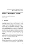
MANET must serve as a router. A scenario of MANET in a military action is illustrated in
Figure 17.1. The two helicopters must communicate indirectly by at least two hops.
Extensive efforts have been devoted to MANET-related research, such as medium ac-
cess control, broadcast, routing, distributed algorithms, and QoS transmission issues. In
this chapter, we will focus on the routing problem, which is one of the most important is-
sues in MANET. In Section 17.2, we review some existing routing protocols for MANET.
Broadcasting-related issues and protocols for MANET are addressed in Section 17.3. Sec-
tion 17.4 reviews multicast protocols for MANET. Routing protocols which guarantee
quality of service are discussed in Section 17.5. How to extend base stations in cellular
networks with ad hoc links are discussed in Section 17.6. Conclusions are drawn in Sec-
tion 17.7.
17.2 UNICAST ROUTING PROTOCOLS FOR MANET
Routing protocols for a MANET can be classified as proactive (table-driven) and reactive
(on-demand), depending on how they react to topology changes [10, 28]. A host running a
proactive protocol will propagate routing-related information to its neighbors whenever a
change in its link state is detected. The information may trigger other mobile hosts to re-
compute their routing tables and further propagate more routing-related information. The
amount of information propagated each time is typically proportional to the scale of the
MANET. Examples of proactive protocols include wireless routing protocol (WRP) [17]
and destination sequenced distance vector (DSDV) [22].
Observing that a proactive protocol may pay costs to construct routes even if mobile
hosts do not have such need, thus wasting the limited wireless bandwidth, many re-
searchers have proposed using reactive-style protocols, in which routes are only construct-
ed on-demand. Many reactive protocols have been proposed based on such on-demand
philosophy, such as dynamic source routing (DSR) [4], signal stability-based adaptive
372
MOBILE AD HOC NETWORKS AND ROUTING PROTOCOLS
Figure 17.1 An example of a mobile ad hoc network.
routing (SSA) [9], ad hoc on-demand distance vector routing (AODV) [23], and temporal-
ly ordered routing algorithm (TORA) [21]. Recently, a hybrid of proactive and reactive ap-
proaches, called the zone routing protocol (ZRP) [10], has also been proposed. Route
maintenance, route optimization, and error recovery are discussed in [35].
17.2.1 Proactive Protocols
One representative proactive protocol is the destination-sequenced distance vector routing
(DSDV) protocol. It is based on the traditional distance vector routing mechanism, also
called the Bellman–Ford routing algorithm [26], with some modifications to avoid routing
loops. The main operations of the distance vector scheme are as follows. Every router col-
lects the routing information from all its neighbors, and then computes the shortest paths
to all nodes in the network. After generating a new routing table, the router broadcasts this
table to all its neighbors. This may trigger other neighbors to recompute their routing ta-
bles, until routing information is stable.
DSDV is enhanced with freedom from loops and differentiation of stale routes from
new ones by sequence numbers. Each mobile host maintains a sequence number by mo-
notonically increasing it each time the host sends an update message to its neighbors. A
route will be replaced only when the destination sequence number is less than the new
one, or two routes have the same sequence number but one has a lower metric.
17.2.2 On-Demand Routing Protocols
An on-demand routing protocol only tries to discover/maintain routes when necessary.
Generally speaking, a routing protocol for MANET needs to address three issues: route
discovery, data forwarding, and route maintenance. When a source node wants to deliver
data to a destination node, it has to find a route first. Then data packets can be delivered.
The topology of the MANET may change. This may deteriorate or even disconnect an ex-
isting route while data packets are being transmitted. Better routes may also be formed.
This is referred to as route maintenance. In the following, we review several protocols ac-
cording to these issues.
17.2.2.1 Route Discovery
Route Discovery of DSR. Dynamic source routing (DSR) [4] is derived from the concept
of source routing. If a source node needs a route to a destination node, it broadcasts a
route request (ROUTE_REQ) packet to its neighbors. On a node receiving this request,
two things may happen. If the node does not know a route to the destination, it appends its
own address to the packet and propagates the ROUTE_REQ packet to its neighbors. Thus,
paths leading to the destination can be tracked by ROUTE_REQ packets. Loops can also
be avoided by looking at the packet content. When the destination receives a
ROUTE_REQ, it returns to the source node a route reply (ROUTE_REPLY) packet con-
taining the route indicated in the ROUTE_REQ. The ROUTE_REPLY then travels,
through unicast, in the reverse direction of the discovered route or on a path already
known by the destination, to the source. The source node, on receiving the ROUTE_
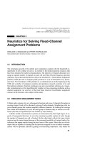
REPLY, will place the route in its route cache. An example is shown in Figure 17.2.
In the second case, an intermediate node is also allowed to return a ROUTE_REPLY if
17.2 UNICAST ROUTING PROTOCOLS FOR MANET 373
it already knows a route fresh enough in its route cache. If so, it simply concatenates the
route in ROUTE_REQ and that in its route cache, and supplies this new route to the
source. Also note that an intermediate node should register the ROUTE_REQ it has re-
ceived to discard duplicate ROUTE_REQs.
Route Discovery of SSA. The signal stability adaptive protocol (SSA) [9] tries to dis-
cover longer-lived routes based on signal strength and location stability. Each link is dif-
ferentiated as strong or weak according to the average signal strength at which packets are
heard. Beacons are sent periodically by each host for its neighbors to measure its stability.
The protocol tends to choose a path that has existed for a longer period of time. Each host
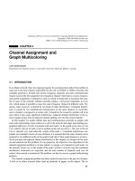
maintains a signal stability table, as shown in Figure 17.3.
Like DSR, the SSA protocol also broadcasts ROUTE_REQ packets to discover routes.
The source can also specify the quality of the route it desires. Possible route qualities are:
374
MOBILE AD HOC NETWORKS AND ROUTING PROTOCOLS
Figure 17.2 An example of route discovery in DSR, with A as the source and D as the destination.
(a) The propagation of ROUTE_REQ packets. An arrow represents the transmission direction from
the corresponding sender to receiver. The sequence of letters associated with each arrow indicates
the traversed hosts that are recorded in the packet header. (b) The transmission of the ROUTE_
REPLY packet from the destination.
(a)
(b)
Figure 17.3 The signal stability table of SSA. Each row is for one link. The signal strength and the
last fields indicate the signal strength and the time, respectively, of the last beacon received. The
clicks field registers the number of beacons that have recently been continuously received. Each link
is classified as SC (strongly connected) or WC (weakly connected) in the set field, according to the
last few clicks received.
Signal
Host Strength Last Clicks Set
c S 10:33 7 SC
G W 10:26 5 WC
STRONG_LINK_ONLY, STRONG_PREFERRED, and NO_PREFERENCE. It is sug-
gested that the STRONG_LINK_ONLY option be used in the first attempt. A receiving
node should help propagating the request if (1) the ROUTE_REQ is received over a strong
link, and (2) the request has not been forwarded previously. The path traversed by
ROUTE_REQ is also appended at the packet. The propagation stops when the destination
is reached or a node having a nonstale route to the destination is reached, on which event a
ROUTE_REPLY packet is sent.
The ROUTE_REPLY packet should travel in the reverse direction of the
ROUTE_REQ. On its way back, each intermediate node can set up the next hop leading to
the destination in its routing table. This is because SSA takes the next-hop routing ap-
proach. Besides, there are some “gratuitous” routes that can be added to the routing table
during the transmission of the ROUTE_REPLY packet. Specifically, if the discovered
route is a Ǟ ··· Ǟ b Ǟ ··· Ǟ d, host b can learn a route to each downstream node.
If multiple ROUTE_REPLYs are received by the source, it can choose the one with the
best quality to use. If the source fails to receive a ROUTE_REPLY packet after a time-out
period, it can broadcast another ROUTE_REQ with other quality options (such as
STRONG_PREFERRED and NO_PREFERENCE) to find a weaker route.
Route Discovery of AODV. The AODV routing protocol [23] is based on the DSDV pro-
tocol described in Section 17.2.1. AODV improves DSDV by using an on-demand philos-
ophy to reduce the route maintenance costs, so hosts that are not on an active path do not
have to maintain or exchange any control information. Each host maintains its own desti-
nation sequence like DSDV to prevent looping and compare the freshness between routes.
A host broadcasts a ROUTE_REQ packet to its neighbors when it determines that it
needs a route to a destination but does not have one available. If a neighbor is an interme-
diate host and doesn’t have any route to the destination, it rebroadcasts the ROUTE_REQ
packet. Also, if a neighbor has a route to the destination but the corresponding sequence
number is less than the sequence number registered in the ROUTE_REQ packet, the
neighbor rebroadcasts the ROUTE_REQ. If a neighbor is the destination host or an inter-
mediate host with a route of a destination sequence number no less than that in the
ROUTE_REQ packet, the neighbor can reply to the request of the source host by using a
ROUTE_REPLY packet containing its own destination sequence number, following the
reverse link leading to the source. On the ROUTE_REPLY’s way back to the source, the
next-hop routing entry can be created in each intermediate host’s routing table (this is sim-
ilar to the procedure described in the SSA protocol).
Route Discovery of TORA. The temporally ordered routing algorithm (TORA) is char-
acterized by a multipath routing capability [21]. Each mobile host is associated with a
height metric. A wireless link is then assigned a direction by going from the host with a
higher metric to the one with a lower metric. By doing so, the network can be regarded as
a DAG (directed acyclic graph) with the destination host as the sink. In graph theory, a
sink is a node in a directed graph with no outgoing links. For example, Figure 17.4 (a) is a
DAG with host D as the sink. No other hosts except the destination host can be a sink.
The formation of a DAG is done by broadcasting a query from the source host toward
the destination host, similar to the earlier protocols. To send a data packet, a host simply
forwards the packet to any neighboring host with a lower metric. Any host receiving the
data packet will do the same thing. Since the network is maintained as a DAG, the data
packet will eventually reach the destination. With such multipath property, one may bal-
17.2 UNICAST ROUTING PROTOCOLS FOR MANET 375
ance/distribute traffic by a randomization technique. Also, some level of fault tolerance to
route breakage can be provided.
Note that for simplicity, the above discussion only covers one DAG. In TORA, one
DAG should be maintained with respect to each destination. So, intuitively, there are total-
ly n DAGs overlapping with each other in a network with n hosts.
17.2.2.2 Data Forwarding
The data forwarding part specifies how data packets are forwarded. Two ways are possi-
ble: source routing and next-hop routing. In source routing, the whole path to be traversed
by a data packet is specified in each packet header, and an intermediate node simply fol-
lows the path to deliver the packet, so there is no need to check the routing tables of inter-
mediate hosts during the packet’s transmission. The DSR protocol falls in this category.
On the contrary, in next-hop routing, only the destination host is specified in the data
packets. Each intermediate host must keep a routing table to determine to which host to
forward the packet. The AODV, TORA, and SSA protocols fall into this category.
The advantage of source routing is that intermediate hosts are free from keeping any
routing information; all the related burdens are put on the source host. The disadvantages
are a longer data packet, which must carry complete routing information, and the over-
head, which will increase proportionally with respect to the path length.
In next-hop routing, routing information is set up in intermediate hosts. Since routing
tables may change dynamically, data packets belonging to the same session do not neces-
sarily follow the same path. This allows some level of fault tolerance. So this approach is
more resilient to host mobility because we are allowed to fix some broken links or change
to other routes locally without this being noticed by the source host, whereas in source
routing, whenever an intermediate host roams away, we must go back to the source host to
discover a new route.
17.2.2.3 Route Maintenance
There are several ways to detect a broken link. In DSR, which uses source routing, when
an intermediate node forwards a data packet to the next node, the former node can snoop
at the latter’s traffic for some predefined time. If the former hears no transmission from
the latter, it assumes that the link to the next node is broken, in which case it will send an
error packet to the source node. For those protocols using the next-hop routing, route en-
tries can be maintained even when no data packets are sent. A host can maintain a list of
all neighbors. Route entries with a nonexistent neighbor can be removed.
In most protocols, on knowing that a route is broken, an intermediate host with unde-
livered data packets at hand can issue an ERROR packet to the source host. On such noti-
fication, the source host can invoke another route discovery to construct a new route.
Also, on its way back to the source, the ERROR packet can be used to invalidate those
stale route entries in other intermediate hosts.
On finding that a route is broken, it is not necessary to construct a completely new
route by issuing another route discovery process. This could be too costly. In most cases, a
route may become broken simply because one intermediate host in the route roams away.
The other part of the route may remain unchanged. There are three protocols employing
this idea to improve performance.
376
MOBILE AD HOC NETWORKS AND ROUTING PROTOCOLS
1. Query localization techniques are proposed in [5] to use the previous route to restrict
the flooding areas on which we propagate the ROUTE_REQ packets to reconstruct
the route. These ROUTE_REQ packets will be sent with limited hop counts. In other
words, the query packets will be limited within the neighborhood of the previous
route only, hence eliminating the possibility of global flooding of the query packets.
2. A simple local route recovery is proposed in [35]. This means that we only fix a
broken link using a partial route local to where the broken link is. When a host finds
that its next host in a route is missing, a local route discovery with a limited hop
count (typically not exceeding 4) will be issued so as to avoid a global flooding.
ROUTE_REQ packets with a limited time-to-live will be issued from the host that
finds the broken link. It is expected that some ROUTE_REQ packets will reach a
host that has an active connection to the destination host. ROUTE_REPLY packets
will be returned to that host too. If this succeeds, the route is remedied locally and
no global flooding of ROUTE_REQ is necessary. However, this mechanism is only
used once because the host that finds the broken link may have a higher probability
of recovering the broken route locally. If this fails, error messages will be delivered
to the source host to trigger a global ROUTE_REQ.
3. A more complicated local route recovery mechanism is proposed in [32]. It is pro-
posed to send a partial route discovery to the destination host from the host in which
a broken link is found. Suppose that a host x finds that its connection to the next
host is broken. It can broadcast a ROUTE_REQ packet with a hop limit equal to the
remaining number of hops it was supposed to traverse to the destination host before
the route was broken. If this succeeds, the route is remedied and no route error will
be reported. Otherwise, a route error will be reported to the host preceding x in the
route, which will in turn repeat the above local route recovery routine (with a hop
limit of one more than the previous host). This is recursively repeated until the bro-
ken route is fixed.
Another approach to reduce the potential cost in the event of route breakage is to keep
backup routes [8, 18]. When a global route discovery is issued, we usually can collect a lot
of routes to the destination. These routes can be kept and used for backup purposes. When
the active (and usually the shortest) one becomes broken, we may replace it by another
backup route. A backup route may be a complete path leading to the destination or a par-
tial route connecting two points in the active route. Of course, backup routes may also be-
come stale due to host mobility and need some maintenance.
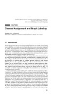
The TORA protocol has an interesting route maintenance process. In TORA, when any
host other than the destination finds that it has become a sink, a partial reversal mecha-
nism will be performed to revert to some link leading to itself. Figure 17.4 illustrates how
this works. Let us assume that the link between hosts G and D is broken. Then host G will
find that it has no outgoing link, as shown in (a). G will reverse all its incoming links,
which will result in hosts F and H becoming sinks, as illustrated in (b). In turn, F and H
will reverse all their incoming links except those just reverted to by G, resulting in the sce-
nario in (c). Similarly, E will find itself to be a sink and do a partial reversal, resulting in
the final DAG in (d). Note that the reversal of links is actually done by changing hosts’
height metrics.
17.2 UNICAST ROUTING PROTOCOLS FOR MANET 377
17.2.3 Hybrid Routing Protocols
The zone routing protocol (ZRP) [10] is a hybrid of proactive and reactive approaches.
With respect to each node, the set of nodes within r hops is called a zone, where r is a pre-
defined value. For each host, routing information inside its zone is constantly collected in
a proactive fashion. To do so, whenever a node’s link state is changed, a notice will be sent
as far as r hops away based on DSDV [22]. Hence, a node always knows how to reach a
node inside its zone. This also limits the number of updates triggered by a link state
change to a local range.
378
MOBILE AD HOC NETWORKS AND ROUTING PROTOCOLS
Figure 17.4 An example of the TORA protocol. Part (a) shows the initial DAG, with D as the sink.
Supposing the link from G to D becomes broken, parts (b), (c), and (d) show how to repair the DAG.
In TORA, each host maintains an order quintuple H
i
= (
i
, oid
i
,
␥
i
,
␦
i
, i). The quintuple is further di-
vided into two parts. The first part contains the first three tuples and represents the reference time
that a link failure is detected downstream from a host in the DAG. The first tuple,
i
, is the time tag,
which is set to the “time” of the link failure. The second tuple, oid
i
, is the originator ID of an event
such as link failure. The third tuple,
␥
i
, is for avoiding looping in the link reversal (not shown in this
example). The second part contains the last two tuples. The first tuple,
␦
i
, is used to order hosts in a
common reference level. The last tuple, i, is the unique ID of a host.
(a)
(b)
(c)
(d)
On the other hand, interzone routing is done in a reactive fashion. It is suggested to use
a modified DSR protocol as follows. When a node needs a route to a node outside its
zone, it performs a border casting by sending a ROUTE_REQ to each node on the “bor-
der” of its zone. On receiving such a packet at a border node, it first checks its intrazone
routing table for existence of a route to the requested destination node. If found, a
ROUTE_REPLY can be sent; otherwise, it performs another border casting in its zone.
This is repeated until a route is found.
A modified source routing style is used for interzone routing. A routing path only con-
tains the border nodes that have to be traversed. This is alright because we always have up-
to-date routing information from a host to its border hosts. Thus, some level of fault toler-
ance (i.e., link change) is provided inside a zone for a path. Once a data packet reaches a
border node whose zone contains the destination, its intrazone routing table will be used
to forward the packet.
17.2.4 Route Bandwidth in a MANET
To investigate the delay and bandwidth of a route in MANET, an implementation result is
reported in [35], based on a next-hop routing protocol on top of the Linux operating system.
The platform used in [35] consisted of a number of notebooks of a variety of speeds
(Pentium 200MMX, Pentium 233MMX, Pentium II 350, etc.), each equipped with a Lucent
WaveLAN wireless card conformed to the IEEE 802.11 MAC protocol operating at the 2.4
GHz band. The transmission rate of these network cards is claimed to be 2 Mbit/sec.
With this platform, the authors observed the effect of hop count on the delay to discov-
er a route. The mobile hosts were placed in a linear manner such that each host could hear
only one or two of its neighbors. The first experiment used the ping command at a certain
host to contact another host, observe the delay, and discover a new route. This experiment
was done in an environment in which all mobile hosts had no up-to-date entries in their
route caches. The result is shown in Figure 17.5. As can be seen, the delay is quite small.
17.2 UNICAST ROUTING PROTOCOLS FOR MANET 379
Figure 17.5 The delay to discover a new route versus route length in a MANET by a ping com-
mand.
Number of hops
The time needed to find a route will increase linearly with respect to the hop count, which
is reasonable.
The second experiment reported in [35] used the ftp command (under binary mode) to
determine the communication bandwidth at different hop counts. The result is shown in
Figure 17.6. Mobile hosts were again placed in a line. In the “simplex” curve, one ftp re-
quest was initiated from a source host to a destination host separated by a certain number
of hops. In the “duplex” curve, two ftp requests were initiated between two hosts in both
directions. One interesting observation is that the bandwidth degrades to 1/2 when the hop
count changes from 1 to 2. The bandwidth further degrades to 1/3 when the hop count
changes from 1 to 3. After three hops, the bandwidth still keeps on degrading, but at a
slower speed. This shows that optimizing the route length is very critical in a MANET as
it improves the end-to-end bandwidth. Of course, the level of contention on the medium
can also be reduced if routes are shorter. How to optimize routes on-the-fly for several
routing protocols is discussed in [35].
It is also worth commenting on the “Upper Bound” curve in Figure 17.6. Obviously,
given a sender–receiver pair that are next to each other, the theoretical bound on band-
width is 2 Mbit/sec. Given a sender–receiver pair that are two hops away, the theoretical
bound will suddenly reduce to 1 Mbit/sec. The reason is that none of the hosts in the (two-
hop) route can transmit at the same time. Following the same line of reasoning, given a
sender–receiver pair that are three hops away, the theoretical bound will reduce to 2/3
Mbit/sec. This results from the effect of signal interference and the hidden terminal prob-
lem [31]. However, after three hops, these factors will disappear and a pipelining effect
may appear. Specifically, two hosts separated by three or more hops may be able to send at
the same time. For instance, in Figure 17.7, we show 10 mobile hosts arranged in a linear
array. Hosts 1, 4, and 7 can send simultaneously; hosts 2, 5, and 8 can send simultaneous-
ly; and hosts 3, 6, and 9 can send simultaneously. This can in fact be formulated by the
well-known graph-coloring problem. Thus, if the “perfect” pipeline can be formed, then
the theoretical upper bound on bandwidth will be 2/3 Mbit/sec.
380
MOBILE AD HOC NETWORKS AND ROUTING PROTOCOLS
Figure 17.6 The bandwidth of a route versus route length in a MANET by a ftp command.
Number of hops
Duplex
Throughput (byte/sec)
17.3 BROADCASTING PROTOCOLS FOR MANET
Broadcasting is a common operation in a network, used to resolve many issues. In a
MANET in particular, due to host mobility, such operations are expected to be executed
more frequently. For example, all the above protocols have to do some sort of broadcasting
in route discovery. Important messages/signals may also be disseminated by broadcasting.
A straightforward approach to perform a broadcast is to use flooding. A host, on re-
ceiving a broadcast message for the first time, has the obligation to rebroadcast the mes-
sage. Clearly, this costs n transmissions in a MANET with n hosts. In a CSMA/CA net-
work, because radio signals are likely to overlap with others in a geographical area,
straightforward broadcasting by flooding is usually very costly and will result in serious
redundancy, contention, and collision, which we refer to as the broadcast storm problem.
This problem was first identified in [19].
By redundancy, we mean that when a mobile host decides to rebroadcast a broadcast
message to its neighbors, all its neighbors may already have the message. In a MANET
environment, redundancy could be very serious. Let us use two examples to demonstrate
how much redundancy could be generated. In Figure 17.8(a), it only takes two transmis-
sions for the white node to broadcast a message, whereas four transmissions will be car-
ried out if flooding is used. Figure 17.8(b) shows an even more serious scenario: only two
transmissions are sufficient to complete a broadcast from the white node, as opposed to
seven transmissions caused by flooding.
The main reason for such redundancy is that radio signals from different antennas are
very likely to overlap with each other. Assuming that the area that can be covered by an
antenna forms a circle, we show in Figure 17.9 the signal overlapping problem corre-
17.3 BROADCASTING PROTOCOLS FOR MANET 381
Figure 17.7 An illustration of the pipelining effect used to derive the theoretical upper bound of
bandwidth in a multihop path. Hosts of the same color can transmit at the same time.
Figure 17.8 Two optimal broadcasting schedules in MANETs. Connectivity between hosts is rep-
resented by links. White nodes are source hosts, and gray nodes are relay hosts.
sponding to the scenario in Figure 17.8(b). The gray levels in the figure indicate the levels
of signal overlapping. As can be seen, many areas are covered by the same broadcast pack-
et more than once. In the worst case, an area can be covered by the packet seven times.
In [19], it is shown, surprisingly, that a rebroadcast can provide at most 61% additional
coverage over the area already covered by the previous transmission. Through calculus, it
is further shown that on average a rebroadcast can cover only an additional 41% of the
area. The calculation is illustrated in Figure 17.10.
Now consider the scenario in which a host X has received the same broadcast packet k
times. We would like to know the benefit of X rebroadcasting the packet. Let us denote the
additional area that can be covered by X’s rebroadcast by EAC(k) (expected additional cov-
erage). Figure 17.11 shows the simulation result. As can be seen, when k Ն 4, the EAC is
quite low (below 5%).
382
MOBILE AD HOC NETWORKS AND ROUTING PROTOCOLS
Figure 17.9 The signal overlapping problem corresponding to the scenario in Figure 17.8(b).
Figure 17.10 Analysis of the extra area that can benefit from a rebroadcast: A sends a broadcast
packet and B decides to rebroadcasts the packet.
In [19], several threshold-based schemes are proposed to relieve the broadcast storm
problem. These protocols are for unreliable broadcast. Reliable broadcasting protocols are
proposed in [1, 20].
17.4 MULTICASTING PROTOCOLS FOR MANET
Previous sections have discussed unicast routing and broadcasting protocols. This section
will introduce multicasting protocols. The multicasting protocols can be classified into
two categories based on how multicast trees are constructed: source-based and core-based
(or group-shared) [29, 34]. The source-based protocol tries to maintain a per-source multi-
cast tree from each source host to every member in the multicast group. Thus, there may
exist multiple multicast trees in the network. The core-based protocol, on the other hand,
uses only one multicast tree rooted at a core host. The tree then spans from the core host to
every member of the multicast group. Although multicasting can be achieved by using
multiple unicast routing, the traffic might be too high and choke the network. Hence,
many multicast protocols have been developed with applications adopting multicasting
technologies. Video conferencing is one important example.
Multicasting in MANET is much more complex than in wired networks because of
host mobility, interference of wireless signals, and the broadcast nature of wireless com-
munication. In the following, we review two such protocols.
17.4.1 ODMRP
In the on-demand multicast routing protocol (ODMRP) [3, 14], the multicast tree is estab-
lished by the source host’s periodical JOIN packets. Consider the example in Figure
17.12(a). The source node S, desiring to send data packets to multicast members, will
17.4 MULTICASTING PROTOCOLS FOR MANET 383
Figure 17.11 Analysis of redundancy: the expected additional coverage EAC(k) (divided by
r
2
)
after a host has heard a broadcast message k times.
384
MOBILE AD HOC NETWORKS AND ROUTING PROTOCOLS
Figure 17.12 An example of ODMRP. (a) Propagation of JOIN_DATA packets. (b) Propagation of
JOIN_TABLE packets. (c) The final multicast tables.
flood a JOIN_DATA to the whole network. When a host receives a JOIN_DATA for the
first time, it will rebroadcast the packet and establish a reverse path to the previous host.
Then each host that is a multicast receiver and has received the JOIN_DATA will reply a
JOIN_TABLE packet to its upstream host on the reverse path. Each host that receives the
JOIN_TABLE for the first time will repeat the process until the source host S is reached.
Figure 17.12(b) shows how these packets are forwarded to S.
On receiving JOIN_TABLEs, a host also has to build its multicast table for forwarding
future multicast packets. For example, when B receives R
1
’s JOIN_TABLE, it will add R
1
as its next hop. When B receives R
2
’s JOIN_TABLE, it will also add R
2
as its next hop.
However, this time, no JOIN_TABLE will be sent to A. The final multicast table for each
host is shown in Figure 17.12(c).
17.4.2 Multicast AODV
The multicast operation of the ad-hoc on-demand distance vector routing protocol (multi-
cast AODV) [27] is extended from the unicast AODV protocol [23]. When a host joins a
multicast group, it has to be added to the corresponding multicast tree. A route request
(RREQ) packet can be broadcast for this purpose. Figure 17.13(a) illustrates the propaga-
tion of RREQ from a host S. If a host receives a RREQ for a multicast group of which it is
not a member or to which it does not have a route, it will rebroadcast the RREQ to its
neighbors.
When a multicast group member receives the RREQ, it will unicast Route Reply
(RREP) packet to the sending host S [shown in Figure 17.13(b)]. As hosts along the path
to the sending host S receive the RREP, they will add entries to their multicast routing ta-
bles for the hosts from which they received the RREP. This process will create the forward
path. Eventually, one or more than one RREP will reach the sending host S. S can pick the
host to which the RREP is returned with the minimum hop count as its next hop leading to
the multicast tree. Then S will unicast a multicast activation (MACT) packet to its next
hop. The next hop, on receiving the MACT packet, will likewise enable for the source host
the route entry with the minimum hop count leading to the multicast tree and send the
MACT. This will be repeated until a member of the multicast tree is reached. Figure
17.13(c) illustrates the final multicast tree that is created.
17.5 QoS ROUTING
The specification and management of quality of service (QoS) is important to support
multimedia applications (such as video and audio transmissions). QoS defines nonfunc-
tional characteristics of a system that affect the perceived quality of the result. In multime-
dia, this might include picture quality, image quality, delay, and speed of response. From a
technological point of view, QoS characteristics may include timeliness (e.g., delay or re-
sponse time), bandwidth (e.g., bandwidth required or available), and reliability (e.g., nor-
mal operation time between failures or down time from failure to restarting normal opera-
tion) [6].
17.5 QoS ROUTING 385
386
MOBILE AD HOC NETWORKS AND ROUTING PROTOCOLS
Figure 17.13 An example of branch addition in the multicast AODV protocol. (a) The propagation
of RREQ packets. (b) The propagation of RREP packets. (c) The final multicast tree.
It is difficult to provide QoS in a MANET due to its broadcast and dynamic nature.
First, unlike wired networks, a wireless link’s bandwidth may be affected by the transmis-
sion activity of its adjacent links. Second, unlike cellular networks, which only need to
guarantee quality for one hop, in MANET we must guarantee the quality for multiple hops
in a path. Third, mobile hosts may join, leave, and rejoin at any time and at any location;
existing links may disappear and new links may be formed as mobile hosts move.
Recently, the QoS transmission problem in a MANET was addressed in several works
[7, 12, 13, 15, 30]. We review some of these works from several aspects in the following
subsections.
17.5.1 QoS at the MAC Layer
Reference [30] considers the medium access control (MAC) layer to support QoS in an ad
hoc wireless network. With their mechanism, real-time hosts contend for access of the
common radio channel based on their priorities. A host’s transmission priority is deter-
mined based on how long it has been waiting for the channel to become idle. It gives pri-
ority access to real-time traffic and ensures collision-free transmission of real-time pack-
ets.
17.5.2 Bandwidth Calculation
In [15], a mechanism is proposed for QoS transmission in a multihop path. A TDMA-
over-CDMA model is assumed. Neighboring hosts are assigned to different transmission
codes to avoid collision. Each code is time-framed. Each frame consists of N time slots,
indexed from 1 to N. Two hosts that are neighbors of a common host cannot send to that
host in the same time slot using the same code or collision will occur. However, if their
transmission codes are separated, their transmission will be fine. Another constraint is that
a host cannot send and receive in the same time slot. For example, Figure 17.14 shows a
contention-free assignment in a path from A to E.
Under such constraints, [15] addresses the bandwidth calculation problem on a multi-
hop path. The set of the common free time slots between two adjacent hosts is defined as
their link bandwidth. Taking Figure 17.15(a) as an example, the link bandwidth between B
and C is BW(B, C) = {4, 5, 6, 7, 8, 9, 10}, and the link bandwidth between B and A is
17.5 QoS ROUTING 387
Figure 17.14 Contention-free assignment under the TDMA-over-CDMA model.
BW(A, B) = {1, 4, 5, 6, 7, 8}. We need to calculate the end-to-end bandwidth from C to A.
First, let us take a set subtraction:
BW(B, C) – BW(A, B) = {9, 10}
These time slots can be used exclusively by C since they are not in the set BW(A, B). Sim-
ilarly, we can take another subtraction to find the exclusive slots for B
BW(A, B) – BW(B, C) = {1}
This means that we can arbitrarily assign slot 9 or 10 to C and assign slot 1 to B to obtain
a bandwidth of one time slot from C to A. The result of choosing slot 9 for C is shown in
Figure 17.15(b). After updating BW(A, B) and BW(B, C), we have BW(B, C) – BW(A, B) =
{10} and BW(A, B) – BW(B, C) = 0/. To match C’s slot 10, we have to pick one slot, say 4,
for B. This results in the assignment in Figure 17.15(c). Finally, because BW(A, B) ʚ
BW(B, C), we pick half of free slots of BW(A, B) for B, say {7, 8}, and arbitrarily pick two
slots for C, say {5, 6}. The final result is shown in Figure 17.15(d), which gives an end-to-
end bandwidth of 4 slots from C to A.
388
MOBILE AD HOC NETWORKS AND ROUTING PROTOCOLS
Figure 17.15 Bandwidth calculation in a two-hop path for QoS transmission.
In Figure 17.15(e), we show a naive solution of assigning slots 4, 5, and 6 to C and slots
1, 7, and 8 to B. The end-to-end bandwidth is only 3.
17.5.3 Ticket-Based QoS Routing
In [7], a ticket-based protocol is proposed to support QoS routing. This protocol maintains
the end-to-end state information at every node for every possible destination. This infor-
mation is updated periodically by a distance-vector-like protocol (namely DSDV [22]).
A source node S, on requiring a QoS route, can issue a number of probing packets each
carrying a ticket. Each probe is in charge of searching for one path, if possible. The basic
idea of using tickets is to confine the number of route-searching packets to avoid blind
flooding (flooding in a MANET is unwise according to [19]). One guideline is: the tighter
the QoS requirements are, the more tickets we should issue. Each probe, on reaching any
intermediate host, should choose one outgoing path that satisfies the QoS requirements. If
a probe enters a node that has no outgoing link satisfying the QoS requirements, the inter-
mediate node sends an invalidated ticket to the destination node. To save the number of
probing packets, several tickets may be carried by one packet and, if so, the probe can be
split in the middle into multiple probes, each carrying some of the tickets and being re-
sponsible for searching a different downstream subpath. Thus, the maximum number of
probes at any time is bounded by the total number of tickets.
For example, Figure 17.16 shows a MANET in which the number associated with each
link is its corresponding bandwidth. The arrows show the progress of two tickets issued
from S to D. It is assumed that a path of bandwidth 3 is required, so the probe going
through C fails but that through B and E succeeds.
17.6 EXTENDING CELLULAR SYSTEMS WITH AD HOC LINKS
Personal communication services (PCS) is one of the fastest growing industries. Such sys-
tems are typically based on a cellular structure. Capacity and channel limitations are im-
17.6 EXTENDING CELLULAR SYSTEMS WITH AD HOC LINKS 389
Figure 17.16 A route search example in the ticket-based QoS routing protocol.
portant concerns. In [25], an architecture called iCAR is proposed to extend the base sta-
tions (BS) with some ad hoc relay links. This will have potential benefits in balancing traf-
fic load between cells, increasing a system’s capacity, and providing services for shadow
areas.
The hardware components of iCAR are illustrated in Figure 17.17. In addition to base
stations and mobile hosts, an ad hoc relay system (ARS) is proposed. An ARS is a wire-
less communication device that can be deployed by a network operator. It has two radio in-
terfaces: a C interface for communication with a base station and an R interface for com-
munication with mobile hosts or other ARS’s. The C interface uses traditional licensed
bands such as 850 MHz or 2 GHz, and the R interface uses an unlicensed band of 2.4
GHz. The R interface is similar to that used in wireless LAN or ad hoc networks.
Each mobile host has, in addition to a C interface in the PCS handset, an R interface for
communication with an ARS. Before communicating with a base station, a mobile host or
an ARS must acquire a unique data channel (DCH). Such a system will have potential
benefits in balancing/distributing traffic load between base stations. We show two exam-
ples here. The first example is called a primary relay, as shown in Figure 17.17(a). Sup-
pose that mobile host X needs to make a call but there is no free DCH in cell B. Typically,
X’s call will be blocked. In iCAR, X can go through the ad hoc links from ARS I to ARS J
and then to a noncongested base station A. So X’s call will not be blocked.
The second example is called secondary relay, as depicted in Figure 17.17(b). Assume
that mobile host X needs to make a call in a congested cell B, but there is no nearby ARS
around X. Suppose that there is a mobile host Y currently occupying a DCH connecting to
B. If Y can be connected to ARS I, which can be connected to the noncongested base sta-
tion A, we can relocate the Y’s call to A so as to vacate a DCH in B. Then X’s new call can
be satisfied. These examples show how ad hoc links can be used in cellular networks to re-
duce the blocking probability. How to place ARS’s is also addressed in [25].
17.7 CONCLUSIONS
In this chapter, we have introduced mobile ad hoc networks. Such wireless network ar-
chitectures can be used when the construction of base stations is too costly or infeasible.
We have discussed unicast, broadcast, multicast, and QoS transmission on a MANET.
390
MOBILE AD HOC NETWORKS AND ROUTING PROTOCOLS
Figure 17.17 Call relays by ad hoc links in the iCAR system: (a) primary relay and (b) secondary
relay.
ACKNOWLEDGMENTS
The authors would like to thank Prof. C H. Lin (National Sun Yat-Sen University) and
Prof. S. Das (University of Cincinnati) for reviewing the contents of this chapter. The au-
thors’ work is supported by the Ministry of Education, ROC, under grant 89-H-FA07-1-4
(Learning Technology) and the National Science Council, ROC, under grants NSC89-
2218-E-008-003, NSC 89-2218-E-008-012, and 89-2218-E-008-013.
REFERENCES
1. S. Alagar and S. Venkatesan, Reliable broadcast in mobile wireless network, MILCOM ‘95,
1995, pp. 236–240.
2. A. Archarys and B. R. Badrinath, A framework for delivering multicast messages in net-
works with mobile hosts, ACM/Baltzer J. of Mobile Networks and Applications, 1, 2, 199–219,
1996.
3. S. H. Bae, S J. Lee, W. Su, and M. Gerla, The design, implementation, and performance evalu-
ation of the on-demand multicast routing protocol in multihop wireless networks, IEEE Net-
work, Jan./Feb., 70–77, 2000.
4. J. Broch, D. B. Johnson, and D. A. Maltz, The dynamic source routing protocol for mobile ad
hoc networks, Internet draft, Dec. 1998.
5. R. Castaneda and S. R. Das, Query Localization techniques for on-demand routing protocols in
ad hoc networks, in Proceedings of MOBICOM ‘99, Aug. 1999, pp. 186–194.
6. D. Chalmers and M. Sloman, A survey of quality of service in mobile computing environments,
IEEE Communications Surveys, Second Quarter, 2–10, 1999.
7. S. Chen and K. Nahrstedt, Distributed Quality-of-Service Routing in ad hoc networks, IEEE
Journal on Selected Areas in Communications, 17, 8, 1488–1505, 1999.
8. Y S. Chen and K C. Lai, MESH: Multi-eye spiral-hopping routing protocol in a wireless ad
hoc network, in Proceedings of ICCCN 2000, Oct. 2000.
9. R. Dube, C.D. Rais, K. Wang, and S. K. Tripathi, Signal stability-based adaptive routing (SSA)
for ad-hoc mobile networks, IEEE Personal Communications, Feb. 1997.
10. Z. J. Haas and M. R. Pearlman, The zone routing protocol (ZRP) for ad-hoc networks, Internet
draft, Aug. 1998.
11. A. Harter and A. Hopper, A Distributed location system for the active office, IEEE Network, 8,
1, 1994.
12. Y K. Ho and R S. Liu, On-demand QoS-based routing protocol for ad hoc mobile wireless
networks, in IEEE Symposium on Computers and Communications ISCC ‘00, 2000.
13. G. D. Kondylis, S. V. Krishnamurthy, S. K. Dao, and G. J. Pottie, Multicasting sustained CBR
and VBR traffic in wireless ad-hoc networks, in IEEE ICC ’00, 2000.
14. S J. Lee, M. Gerla, and C C. Chiang, On-demand multicast routing protocol (ODMRP) for ad
hoc networks, Internet draft, draft-ietf-manet-odmrp-01.txt, Jun. 1999, work in progress.
15. C. R. Lin and J S. Liu, QoS routing in ad hoc wireless networks, IEEE Journal on Selected
Areas in Communications, 17, 8, 1426–1438, 1999.
16. IETF MANET Working Group, />17. S. Murthy and J. J. Garcia-Luna-Aceves, An efficient routing protocol for wireless networks,
ACM Mobile Networks and Application, Oct. 183–197, 1996.
REFERENCES 391
18. A. Nasipuri and S. R. Das, On-demand multipath routing for mobile ad hoc networks, in Pro-
ceedings of ICCCN ‘99, Oct. 1999.
19. S Y. Ni, Y C. Tseng, Y S. Chen, and J P. Sheu, The broadcast storm problem in a mobile ad
hoc network, in Proceedings of MOBICOM ‘99, Aug. 1999, pp. 151–162.
20. E. Pagani and G. P. Rossi, Providing reliable and fault tolerant broadcast delivery in mobile ad-
hoc networks, Mobile Networks and Applications, 4, 175–192, 1999.
21. V. D. Park and M. S. Corson, A Highly Adaptive distributed routing algorithm for mobile wire-
less networks, in Proceedings of INFOCOM ‘97, April 1997.
22. C. Perkins and P. Bhagwat, Highly dynamic destination-sequenced distance-vector (DSDV)
routing for mobile computers, in ACM SIGCOMM Symposium on Communications, Architec-
tures and Protocols, September 1994, pp. 234–244.
23. C. Perkins and E. M. Royer, ad hoc On demand distance vector (AODV) routing (Internet draft),
August 1998.
24. R. Prakash and M. Singhal, Low-cost checkpointing and failure recovery in mobile computing
systems, IEEE Trans. on Parallel and Distributed Systems, 7, 10, 1035–1048, 1996.
25. C. Qiao, H. Wu, and O. Tonguz, iCAR: An integrated cellular and ad-hoc relay system, in IEEE
International Conference on Computer Communications and Networks, 2000.
26. G. Malkin, RIP Version 2 carrying additional information, RFC, 1723, 1994.
27. E. M. Royer and C. E. Perkins, Multicast operation of the ad-hoc on-demand distance vector
routing protocol, in Proceedings ACM/IEEE MOBICOM ‘99, Seattle, WA, Aug. 1999, pp.
207–218.
28. E. M. Royer and C K. Toh, A Review of current routing protocols for ad hoc mobile wireless
networks, IEEE Personal Communications, Apr., 46–55, 1999.
29. L. H. Sahasrabuddhe and B. Mukherjee, Multicast routing algorithms and protocols: A tutorial,
IEEE Network, Jan./Feb., 90–102, 2000.
30. J. L. Sobrinho and A. S. Krishnakumar, Quality-of-Service in ad hoc carrier sense multiple ac-
cess wireless networks, IEEE Journal on Selected Areas in Communications, 17, 8, 1353–1368,
1999.
31. A. S. Tanenbaum, Computer Networks, Prentice Hall, Englewood Cliffs, NJ, 1996.
32. C K. Toh, A Novel Distributed routing protocol to support ad-hoc mobile computing, in Pro-
ceedings 1996 IEEE 15th Annual International Phoenix Conference Computing and Communi-
cations, 1996, pp. 480–486.
33. R. Want, A. Hopper, V. Falcao, and J. Gibbons, The Active Badge Location System, ACM Trans.
on Information Systems, 10, 1, 91–102, 1992.
34. B. Wang and J. C. Hou, Multicast routing and Its QoS extension: Problem, algorithms, and pro-
tocols, IEEE Network, Jan./Feb., 22–35, 2000.
35. S L. Wu, S Y. Ni, Y C. Tseng, and J P. Sheu, Route maintenance in a wireless mobile ad hoc
network, Telecommunication Systems, 18, 1/3, 61–84, 2001.
392
MOBILE AD HOC NETWORKS AND ROUTING PROTOCOLS