Tài liệu Mạng và viễn thông P17 pdf
Bạn đang xem bản rút gọn của tài liệu. Xem và tải ngay bản đầy đủ của tài liệu tại đây (1.45 MB, 10 trang )
17
Fibre
in
the
Loop
(FITL)
and
Other
Access
Networks
The advent of optical fibre communication has coincided with a worldwide trend towards
deregulation of public telecommunication network services. This has caused rapid heavy
investment
in
optical fibre networks, including access networks for the connection
of
customers.
This in turn has brought not only focus onto the development
of
new modulation and
multiplexing technologies for use in conjunction with optical fibres themselves, but also the
development of new techniques to enable the better usage of existing copper and coaxial cable
access network lineplant, as encumbent operators attempt to make the best of the installed
lineplant. In this chapter we review some of the most important of these new technologies.
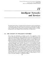
17.1 FIBRE ACCESS NETWORKS
A
number of new terms have appeared to describe different initiatives developing
solutions for the deployment of fibre cables in business and residential customer access
networks. These can all be classified as various forms of
fibre
in
the loop
(FZTL).
Subcategories of
FITL
are
jibre to the building
(FTTB),
providing direct fibre
connection of business customers, office buildings of campus sites;
fibre
to
the home
(FZTH),
providing
video
on
demand
(VoD),
cable television and telephone services to
residential premises
andfibre to the curb
(FTTC),
whereby the fibre extends only as far
as the streetside cabinet, from which existing copper or coaxial lineplant can be used to
connect customer premises. Figure
17.1
illustrates these various concepts.
17.2 FIBRE TO THE BUILDING (FTTB)
The main driver for
FTTB
(fibre to the building)
has been the boom in demand from
business telecommunications users for line capacity. It is nowadays usually most
economic for network oeprators to lay fibre optic cable directly into large business
329
Networks and Telecommunications: Design and Operation, Second Edition.
Martin P. Clark
Copyright © 1991, 1997 John Wiley & Sons Ltd
ISBNs: 0-471-97346-7 (Hardback); 0-470-84158-3 (Electronic)
330
FIBRE
IN
THE LOOP
(FITL) AND
OTHER ACCESS NETWORKS
copper
mc
and
coax
Figure
17.1
Fibre
in
the
loop
(FITL)
premises rather than multiple pair copper cables. First, the fibre optic cable occupies far
less valuable duct space; in addition, it does away with the need for amplifiers and other
regenerative devices within the access network; finally, optical fibre provides plentiful
capacity to meet future customer orders for bandwidth.
In the simplest realization of FTTB only a standard multiplexor and an
optical line
terminating unit (OLTU)
are required in the customer’s premises and at the exchange
to provide a range
of
different line connections with different bitrates and line
interfaces.
A
number of new metropolitan network operators have emerged which are
building exactly such networks.
Metropolitan Fibre Systems (MFS), City
of
London
Telecommunications (COLT)
and
Teleport
are examples. Their networks consist of
fibre optic access networks, built in redundant multiple ring topologies, using
SDH
(synchronous digital hierarchy)
transmission technology (Chapter
13).
They, and
similar network operators have existing networks in many large cities across the globe.
The in-building multiplexor at the customer site may either be dedicated to a single
customer and installed in his offices, or in many cases be shared by a number of
different tenants
of
a large office complex; in this case being installed in a small
equipment room rented by the network operator within the building as a common
attachment point.
17.3
FIBRE
TO
THE CURB (FTTC)
Fibre to the curb (FTTC)
is a natural extension of the second case of
fibre to the
building.
In
fibre to the curb
a shared mulitplexor is installed in a streetside cabinet
rather than in an equipment room on a customer’s premises. From this point, existing
copper lineplant is used to connect to individual customers. The main benefit of FTTC
is the ability to rationalize the copper junction cabling (i.e. that between the streetside
distribution cabinets
and the exchange) as a first step in access network modernization,
without requiring the upheaval or investment that would result from wholesale
replacement
of all copper lineplant.
FIBRE TO THE HOME (FTTH)
331
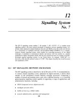
Figure
17.2
A streetside cabinet providing for fibre
to
the curb
(FTTC)
(Courtesy
of
Siemens
AG)
The
OPAL (optical access line)
system of the Deutsche Telekom is an example of an
FTTC system. The
OPAL
system was used extensively in the penetration and modern-
ization of the former East German telephone network following the reunification of
Germany in
1990.
17.4
FIBRE TO THE HOME (FTTH)
The cabling of fibre directly into residential customers’ homes is usually carried out with
the main objective of providing cable television or other video entertainment services like
video
on
demand
(VoD).
Here, the emphasis of new
passive optical networks (PON)
has
been the establishment of low cost, low maintenance access networks that do not require
active electronic components installed in the street environment.
17.5
BROADBAND PASSIVE OPTICAL NETWORK
Broadband Passive Optical Network (BPON)
is a simple approach to broadband
networking with a very clearly focused commercial application. It is a technology
332
FIBRE
IN
THE
LOOP
(FITL)
AND OTHER ACCESS NETWORKS
proposed and developed by British Telecom that is intended to bring fibre to the home.
Basically, it is a network composed of monomode fibres (either in a ring or star
topology) connecting telephone exchanges and peoples homes, allo’wing not only basic
telephony but also the ‘broadcasting’ of cable television and video programmes.
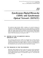
The foundation of BPON is a technique known as
TPON
(telephony passive optical
network).
This is the method by which telephone services are provided in residential
homes by means of fibre connected back to the exchange (again in either
a
ring or star
topology). Optical couplers enable the various fibre distribution joints to be made
without active electronic components (Figure 15.3). Individual calls from customers are
time division multiplexed (TDM) at the exchange and selectively demultiplexed by the
appropriate subscriber’s receiver.
By using TDM and a technique known as
wavelength division multiplex
(WDM,
basically the use of another laser of a different wavelength light), other broadband
signals may be carried over the same fibre network. Thus the broadcast of cable
television and video services is possible simultaneously with the telephone operation.
This is the principle of BPON (Figure 17.3).
17.6 ACCESS NETWORK INTERFACES
The emergence of new active technology in the access network between customer
premises and the exchange site has naturally brought with it new problems and
opportunities. The problems arise from the need to devote effort to standardization
of
new interfaces, the opportunity is the new service functionality thereby made possible,
together with the scope for network restructuring and cost optimization.
Two types of interface are now being addressed by standardization work on trans-
mission technology for the access network. These are
local exchange
(LE)
to
access
network
(AN)
interfaces (designated
V5
interfaces
by ETSI) and the
subscriber-network
interface
(SNI).
Figure 17.4 illustrates these interfaces.
1300
nm
1550
nm
Figure
17.3
Broadband passive
optical
network (BPON)
access
network
(AN)
Figure
17.4
Access network interfaces
17.7 ETSI
V5
INTERFACES
In conjunction with the modernization of the East German telephone network and the
introduction of its
OPAL
(optical access line)
technology, Deutsche Telekom
recognized the potential for savings in access network lineplant, in the number of
customer ports needed on telephone exchanges and in the number of telephone
exchanges needed to supply a given region. This could be done by inclusion of
concentration
functions within the
OPAL
network. This lead to the development of the
ETSI V5 interfaces.
As
Figure 17.5(a) illustrates, the access network need only support sufficient
connections across itself for the actual number of telephone calls in progress.
Historically, copper access networks had provided a permanent connection line for
each end user (Figure 17.5(b)). This configuration requires many more connections
within the
access network
(AN)
and many more
local exchange
(LE)
ports.
In the example of Figure 17.6, ten end user terminals are connected to the local
exchange. It is assumed that only a maximum of two of these terminals are in use at
any one time. In the case of Figure 17.5(a), a concentrating function (i.e. simple
switching function) within the access network ensures that only two through
connections are required to be carried and only two ports are required at the exchange.
In Figure 17.5(b), no
concentration
is undertaken by the access network,
so
that ten
connections and ten exchange ports are necessary.
Before the access network can undertake the concentration function, a new signalling
procedure must first be defined, because it would otherwise
no
longer be possible for the
exchange to know (merely by port of origin) which customer was wishing to make a
call. The local exchange requires this information
so
that the correct customer is billed
for the call. Similarly, for incoming calls, the local exchange must be able to signal to
the access network which destination customer is to be connected. This signalling is
defined in the ETSI specifications for its V5.1 and V5.2 interfaces.
334
FIBRE
IN
THE
LOOP
(FITL)
AND
OTHER
ACCESS
NETWORKS
.H
c)
E!
d
V5.2
INTERFACE
335
17.8
V5.2
INTERFACE
The V5.2 interface is defined in ETSI standard ETS
300
347. It defines a method for
connecting up to 480 customer lines
of
64 kbit/s capacity (480 simple telephone lines,
240 ISDN basic rate access lines or 16 ISDN primary rate access lines
or
an appropriate
mix thereof) via an
access network
(AN)
to a telephone or ISDN
local exchange
(LE).
The
access
network
may be connected using up to sixteen 2Mbit/s lines to the
local
exchange.
Figure 17.6 illustrates the V5.2 interface.
As the V5.2 interface provides for a concentration function (like Figure 17.5(a))
to
be
undertaken by the access network, the number
of
traffic-carrying channels at the V5.2
interface (between AN and LE) may be less than the number of customer connections
required from the AN to customer premises. The protocol
of
V5.2 is complex and not
covered in detail here. It bears some resemblance to ISDN D-channel signalling (ITU-T
Q.931) and is
OS1
model compliant. Main elements and terminology of the interface are
as follows.
Bearer channel: this is a channel with a bitrate
of
64 kbit/s (or an integral multiple
thereof) which is used to carry customer telephone signals or ISDN data services.
Bearer channel connection (BCC) protocol: this is a protocol which allows the LE to
control the AN in the allocation of
bearer channels.
It
is one
of
the types
of
information which may be carried by an
information path.
Communication path (c-path): this is the path needed to carry signalling or data-
type information across the V5.2 interface. Apart from the
BCCprotocol,
a
c-path
is
also used for carriage of the ISDN D-channel signalling and packet or frame data
originated by the various customer ISDN connections.
Communication channel (c-channel): this is a 64kbit/s allocation at the V5.2
interface configured to carry a
communication path.
Logical communication channel (logical c-channel): this is a group of one or more
c-paths.
up
to
480
customer
connections
of
64
kbitls
local
exchange
(LE)
Figure
17.6
V5.2
interface between local exchange and access network
336
FIBRE
IN
THE
LOOP
(FITL)
AND
OTHER
ACCESS
NETWORKS
Physical communication channel (physical c-channel): this is an actual 64 kbit/s
timeslot allocated at the V5.2 interface for carrying logical
c-channels.
A
physical
c-channel
may is configured for communication and signalling and may not be used
to carry
bearer channels.
Active c-channel: this
is
a
physical c-channel
which is currently carrying a
logical
c-channel.
When not carrying a
logical channel,
the same
physical c-channel
becomes
a
standby c-channel.
Standby c-channel: this is a
physical c-channel
which is not currently carrying a
logical c-channel.
Thus the 64kbit/s
timeslots
traversing the V5.2 interface are subdivided into
bearer
channels
and
c-channels
by assignment (i.e. when the network is configured). The
bearer
channels
serve to carry user telephone and ISDN or data connections. The
c-channels
serve (on an as-needed basis) to carry the
BCCprotocol
for allocation of
bearer channels
to individual calls and to carry the ISDN D-channel signalling and data information
between the end user terminal and the local telephone or ISDN exchange.
17.9 V5.1 INTERFACE
The V5.1 interface is a simpler version of the V5.2 interface in which the concentration
feature (Figure 17.5(a)) is not included. V5.1 should be seen as the first step to V5.2. It
allowed the adoption of new generation access network technology while the full
specification and development of the concentration function (V5.2)
took
place.
17.10 SIGNIFICANCE OF THE
V5.x
INTERFACES
The V5.1 and V5.2 intefaces (or V5.x interfaces, as they are collectively known) provide
for a standard means of connecting
remote switching
units
(RSUs)
of ISDN or
telephone exchanges back to a central main exchange site (Figure 17.7).
exchange
(site
of
main
processor)
Figure
17.7
Use
of
a
V5
type interface to support remote switching units
RE-USE
OF
EXISTING COPPER ACCESS NETWORKS
337
A network topology comprising central main exchange sites and remote switching
units interlinked by standardized interfaces
(V5)
has significant benefits for public
telephone network and ISDN operators. First, the number
of
exchange processor sites
may be dramatically reduced (typically to a number of tens in a given country). This has
significant investment and operational cost benefits. Second, the
remote switching units
(RSUs) may be purchased from multiple vendors, thus giving the network operator
more leverage on price for these devices, which are needed in relatively high volume.
This may lead to reluctance
on
behalf of the switch equipment manufacturers to
developing it.
17.11 RE-USE
OF
EXISTING COPPER ACCESS NETWORKS
The boom in demand for 2Mbit/s and higher bit rate connection services created by
optical fibre technology has also had a spin-off in stimulating the development of
technologies which attempt to re-use the existing copper and coaxial cable
infrastructure. Three new technologies of particular interest are
e
HDSL (high bitrate digital subscriber line)
e
ADSL (asymmetric digital subscriber line)
e
HFC (hybridfibrelcoax networks)
We discuss them in turn.
17.12 HDSL (HIGH BITRATE DIGITAL SUBSCRIBER LINE)
HDSL is
a
technique providing for full duplex
2
Mbit/s access lines using two or three
copper pairs. The technique is particularly designed to serve high speed business user
needs over distances up to
3
km without having to replace the copper access network or
lay new lineplant. As well as being used to provide the complete access line from
customer site to exchange building, HDSL is also likely to play an important role as a
complement to
FTTC (Jibre to the curb)
networks. In such usage HDSL provides for
the final few metres from the FTTC street cabinet into the customer premises, thus
potentially saving the need for a new cable or cableduct into the customer premises.
17.13 ADSL (ASYMMETRIC DIGITAL SUBSCRIBER LINE)
ADSL uses technology similar to HDSL, but instead of providing
2
Mbit/s bitrates in
both directions, an asymmetric pair of bitrates are provided.
Downstream
(i.e. from the
exchange to the customer) a high bitrate of between
1.5
Mbit/s and
8
Mbit/s is intended
to provided for boradcast and
video-on-demand
(VoD)
services, as well as telephony.
338
FIBRE IN THE LOOP
(FITL)
AND OTHER ACCESS NETWORKS
Figure
17.8
ADSL
(asymmetric digital subscriber
line)
Upstream
(i.e. from customer to exchange) the bitrate provided is much lower (between
16
and
450
kbit/s). This bitrate is only intended to be sufficient for telephony and for
control of the network services (e.g. to say which video should be delivered). Figure
17.8
illustrates
ADSL.
17.14
HYBRID FIBRE/COAX (HFC) NETWORKS
There is considerable interest amongst coaxial cable TV companies to upgrade their
networks for the needs of coming
interactive video
and
multimedia
services, and in the
short term simply to offer public telephone service in addition to television broadcast
service to their customers. This has led to a number of developments for telephony over
coaxial cable TV networks and integration of coaxial cable networks (for attachment of
customer premises) into fibre networks. These are sometimes referred to as
fibre to the
curb
(FTTC)
technologies, sometimes more specifically as
HFC
(hybridfibre/coax).