Tài liệu Phần mềm xác định radio P7 pdf
Bạn đang xem bản rút gọn của tài liệu. Xem và tải ngay bản đầy đủ của tài liệu tại đây (527.77 KB, 33 trang )
Part III
Baseband Technology
‘Software runs on Silicon’ – and in the case of SDRs today, the competition between
approaches and technologies for exponentially increasing baseband processing requirements
is proving a fertile ground for innovation, in both conceptual approaches and implementation
architectures.
Software Defined Radio
Edited by Walter Tuttlebee
Copyright q 2002 John Wiley & Sons, Ltd
ISBNs: 0-470-84318-7 (Hardback); 0-470-84600-3 (Electronic)
7
Baseband Processing for SDR
David Lund
a
and Bahram Honary
b
a
HW Communications Ltd.
b
Lancaster University
Many technologies require substantial research and development to facilitate the emergence
of mature and generic software defined radio architectures, as will be evident from a perusal
of the contents of this volume or the other literature in the field. Our own chapter focuses upon
the broad ranging topic of baseband processing, an important and central element of such
architectures. Alongside networking of these enhanced capability and flexible systems, the
radio frequency processing aspects of the physical layer are required to accommodate a
flexible range of different frequencies, formats, and environments. Baseband processing is
perhaps one of the most potentially fruitful areas of development anticipated over the next
few years – indeed, significant progress is already evident.
7.1 The Role of Baseband Architectures
The baseband of any radio system is responsible for digitally transforming raw data streams
into the correct format ready for transmission over a known wireless channel. In a transmitter
this simply consists of formatting of the data and introduction of any redundancy required to
improve reception. At the receiver, the information from the radio frequency front end has to
be carefully analyzed in order to extract correctly the data which was intended for reception.
This requires synchronization, demodulation, channel equalization, channel decoding, and
multiple access channel extraction. These, and many more functions, are linked together to
form a chain of processing functions, providing a pipeline through which the data and its
associated overhead are passed.
The architecture of this baseband processing chain is structured to reflect the type of
wireless channel and other supporting functions over which data is to be transmitted. Differ-
ent modulation, channel coding schemes are chosen to maximize throughput over the parti-
cular channel, which itself may be influenced by the application (e.g. required data rate).
Multiple access methods are chosen to maximize the number of transmitters which can
effectively and simultaneously share the spectrum. Support functions such as synchroniza-
tion, equalization, and spatial diversity algorithms all enhance the basic transmission format
Software Defined Radio
Edited by Walter Tuttlebee
Copyright q 2002 John Wiley & Sons, Ltd
ISBNs: 0-470-84318-7 (Hardback); 0-470-84600-3 (Electronic)
at the expense of extra processing and power consumption, the latter being particularly
important within the context of portable devices.
The majority of today’s air interfaces are subject to a standardized specification which
strictly defines the transmission formatting for a particular system. For example, GSM,
UTRA, and IS-95 specify just a few of the individual formats for mobile wireless telecom-
munication systems. Digital audio broadcasting (DAB) and DVB-T specify formats for
terrestrial broadcasting systems and DVB-S for satellite broadcasting. Many others define
high bit rate wireless systems for short range networking, fixed wireless access, and other
applications. A software defined radio may be designed to tranceive using a variety of such
available standards. It may even participate ad hoc, as and when bandwidth may be available.
Any of the standard transmission formats may be chosen which may provide the necessary
level of service as the users’ application requires.
Research in SDR commonly takes a top down approach. Evaluation of the market looks at
what the user requires in terms of application. Network developers look at how to provide
such applications and services to the user. Equipment developers develop and use compo-
nents to build the infrastructure needed to implement the networks and terminals.
Equipment developers will frequently take predominantly off-the-shelf component tech-
nologies and, maybe after some specific modification, integrate them into infrastructure
equipment. This is certainly how second-generation mobile equipment has been developed,
with GSM terminals commonly containing hybrid application specific integrated circuit
(ASIC) devices based upon a particular microprocessor (mP) or digital signal processor
(DSP) core.
New component technologies are rapidly emerging which complement the now traditional
mP and DSP technologies. Field programmable gate array (FPGA) and new reconfigurable
fabric processors give an alternative edge to the use of aging mP and DSP technologies.
The remainder of this chapter describes a range of technologies and techniques presently
available for implementation of the baseband processing subsystem. The concept of flexible
processing is introduced to describe the higher level problems associated with using such
technology. The status of currently available component technologies is described, illustrat-
ing the wide range of processing resource already available today. These are presented to
developers of SDR-based equipment, providing insights into how they may be used for
different algorithmic purpose.
The introduction of new processing technologies also requires development of new design
tools and methods. The status of such tools is also described with discussion of requirements
not only for initial design of an SDR system but also its maintenance. A discussion of object-
oriented methods illustrates how the high level software developer may be given the neces-
sary visibility and understanding of the processing resources available. With such visibility,
SDR operators and maintainers can then allocate the necessary time critical baseband proces-
sing chains to a multitude of processing resources with maximum efficiency.
7.2 Software Radio – From Silicon to Software
It is important here to recognize the context within which, for the purposes of this chapter, we
use the term ‘software’ and the consequent breadth of the requirement. The Cambridge
International Dictionary of English gives the following simple definition:
Software –‘the instructions which control what a computer does’.
Software Defined Radio: Enabling Technologies202
So, for an easy method of translation to the context of software radio systems, which is
simply a new advanced method of communication, we could replace the term ‘computer’
with the term ‘communication system’ to get:
Software –‘the instructions which control what a communication system does’.
The computer is a relatively simple system which is controlled by relatively simple soft-
ware. It is clear to see that software in the context of SDR is much more elaborate and can in
fact be considered to be two-tiered. Software (tier 1) is required to define the computation and
software (tier 2) is required to control the mode of operation of this computation within the
communication system.
1
Much research is today being carried out in order to determine the best methods to
architecturally define software radio with its associated reconfigurable systems and
networks.
2
Issues such as quality of service, value added service provision, and the huge
task of managing all of this are being defined and will require substantial advances in
implementation level technology to automate these aspects.
Quality of service (QoS) guarantees are becoming more and more an important function-
ality for the future of mobile telephony and data transfer services. QoS applies a policy to a
communication service to which the system must adhere. For example, the resource reserva-
tion protocol (RSVP) service is such a method for providing a level of QoS in fixed network
applications. A data transfer session begins by reserving bandwidth through a network or the
Internet. A route of fixed bandwidth is reserved from the data source to its destination by
negotiating with routers along the way. Once the bandwidth is reserved, the data transmission
can take place with a guaranteed pipeline of fixed bandwidth. The application transferring the
data can then guarantee the quality of service supplied to the user. QoS is a topic originally
pioneered by researchers in computer-based fixed networks. As third-generation mobile
networks are developing, the concept of QoS is emerging as an important requirement for
provision of a wide range of high quality data services to the mobile user.
Network management is also a hot topic in the quest for improving the mobile and Internet
experience. Providing efficiency in the system along with network management allows easy
deployment and control of systems and hence efficient service to the user. Second-generation
mobile networks consist of mobile terminals, base stations, and switching centers. Third-
generation networks provide much more functionality in order to improve user services.
Various domains and strata providing different levels of data access and control are defined,
allowing the capability to provide advanced, user specific services across a broad range of
environments and across multiple networks [1]. Network management of these, already
multimode, systems is proving to be a huge task. The concept of software radio and the
advent of reconfigurable processing systems makes the organization and management of the
network even more complex, as the majority of functionality in the network becomes capable
of being modified with only the actual hardware architecture remaining static.
The CAST
3
project illustrates the need for advanced management methods by focusing on
Baseband Processing for SDR 203
1
A similar distinction, using the terms ‘software signal processing’ and ‘software control’, is made and explained
further in Chapter 1.
2
For an overview of such research in Europe see Dillinger and Bourse in Software Defined Radio: Origins, Drivers
and International Perspectives’, Tuttlebee, W. (Ed.), John Wiley & Sons, Chichester, 2002, Chapter 7.
3
Configurable radio with Advanced Software Technologies (CAST) project is European Commission Information
Society Technologies (IST) funded Project, IST-1999-10287. HW Communications Ltd are primary contractors in
this project, within which the authors of this chapter actively participate.
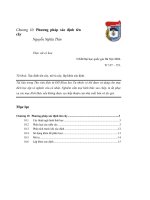
the use of organic intelligence to cope with the enormous range of situations and scenarios
which have to be managed. Figure 7.1 illustrates how an architecture based on organic
intelligence can be used to manage the multitude of reconfigurable elements in a network
[6,17,38].
Other approaches to the problem use traditional procedural approaches whereby a fixed set
of rules governs the management operation depending upon the status of the system. It
becomes quite clear when reviewing the different proposed systems that a combination of
intelligence and procedural rules is essential to cope with the immense multitude of operating
scenarios which are available.
Overall, the high level visionary architectures of reconfigurable mobile networks place a
huge demand on the technologies which have the responsibility of processing all of this.
Combined with greedy demand for data bandwidth and strict QoS restrictions the resultant
demands placed on silicon processing technologies are seen to be growing in an unprece-
dented manner.
There are two demands made by such systems which quite simply describe the major
developments required of the physical processing technology, namely demands for:
† increased processing capability
† increased dynamic capability
These are not, however, just tasks for the silicon engineering industry.
Today’s complex semiconductor devices require powerful tools to aid designers in using
the technology quickly and efficiently. The days of Karnaugh maps for logic minimization are
now far in the distant past. Modern processing technologies exceed tens of millions of logic
gates. Manual design, even on circuits which are today considered simple, is impossible.
Increasing the dynamic capability of a system not only increases its range of operation, but
also increases its lifetime, extending the system maintenance requirements.
To summarize, three major areas of advance are required in order to provide the dynamic
processing capabilities essential to support future reconfigurable communication systems. A
number of key challenges and questions arise in each of these areas, summarized below. It is
Software Defined Radio: Enabling Technologies204
Figure 7.1 CAST network management architecture [6]
the lack of a single simple criterion which restricts evaluation of the many innovative alter-
natives proposed today as possible baseband technology solutions.
1. Baseband component technologies
– dynamic capability – how flexible are different processing devices?
– processing capability – how powerful are different processing devices?
– physical constraints – what are their physical limitations?
2. Design tools and methods
– standardized tools and methods – global compatibility and coherence.
– specification tools and methods – transferral of design information.
– mixed mode capability – mixed component technologies imply the need for mixed tool
environments.
– tool processing requirements – can a highly complex system be simulated?
– compliance to design procedures – design flows for different technologies and combi-
nations.
– algorithm processing requirements – to provide enhanced automated design decisions.
– automated hardware selection for algorithms – also for automated design decisions.
– system simulation and emulation – testing methods at different levels.
3. System maintenance
– object oriented system control – control of low level processing resource by higher
layer distributed control.
– configuration and reconfiguration mechanisms – controlling the physical processing
resources.
– initial set up and configuration – how is a system initialized?
– automatic intelligent decisions – higher capability requires more complex decisions.
– capability classification – knowledge of the processing system is required for in-system
decision making.
– resource allocation – efficiently allocating functions to processing resources.
– configuration update procedures – methods of securely controlling and updating dyna-
mically distributed systems.
It is evident that the advances in silicon technology today are outstanding and provide huge
capabilities. However, in order to use these technologies efficiently, more development is
required in order to support the silicon. From the component technologies viewpoint, the
evolution of the personal computer has reflected advancement in microprocessor and RAM
technologies. Support and drive has also however been required from providers of operating
systems, development tools and system maintenance. As with the PC, provision of generic
reconfigurable systems will not just rely on a small number of technologies. Different silicon
devices are now essential to provide high capacity dynamic processing. It is shown later how
some of these essential new silicon technologies presently lack the required support from
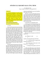
development tools and maintenance. Figure 7.2 illustrates the wider context of the real
enabling technology required for software radio.
Existing methods of using software to define the function of a processing system are well
defined when using microprocessor-based resources. Application and service developers are
Baseband Processing for SDR 205
able to use this resource, without knowledge of its existence, to provide high quality and
efficient desktop based data services such as real time video, radio, and many more. Much
development is required in order to support the increased range of processing media avail-
able. Software radio systems depend wholeheartedly upon this new multitude of processing
resource. Allowing the application and service providers transparent access to this newly
defined resource will require substantial development in all three areas described above.
The subsequent sections of this chapter are devoted to an examination of the current status
of component technologies, design tools and methodologies, and system design and main-
tenance.
7.3 Baseband Component Technologies
Until relatively recently, the majority of software radio research had focused mainly on the
use of software and digital signal processors [12]. Arguably, this is the simplest technology to
implement, but performance of a system consisting of processor and software only is not yet
powerful enough for the high data rate requirements of systems targetted for third-generation
(3G) mobile communications. Several recent papers have described the application of FPGAs
in software radio [2,9,10], but few have attempted to tackle the issues relating to the config-
uration and reconfiguration during an online service transmission.
No single silicon technology is more important than another when it comes to the design of
efficient processing systems. Each processing algorithm has a different combination and set
of discrete operations. The combination of logic operations, adds, subtracts, multiplies,
divides and condition operations is different for each algorithm. The first digital signal
processors (DSP) were optimized mainly for the huge demand of pipelined multiply accu-
mulate (MAC) operations which form the basis of most discrete signal processing algorithms.
Software Defined Radio: Enabling Technologies206
Figure 7.2 The breadth of enabling technology required to support SDR
Figure 7.3 illustrates how the FPGA can provide a solution for systems requiring both high
performance and a high degree of function capability. At one extreme, hardwired devices,
such as an ASIC, can only perform a limited function; they do, however, provide a very high
performance. The DSP, being software programmable, can offer an almost unlimited function
capability, but, of course, the serial processing nature of traditional DSPs does limit perfor-
mance.
Figure 7.4 illustrates how the FPGAs processing resource is able to provide this combi-
nation of high function with high dynamic capability. Any processing algorithm can be
decomposed into subelements which incrementally carry out the computation required by
the algorithm. Each of these subelements has dependencies upon the data available as a
result of other subelements’ processing. In Figure 7.4, subelement 2 is dependant upon 1
and subelement 4 is dependant upon 3. Subelement 5 is dependant upon the result of 2 and
4. A single mP or DSP software based computation of the algorithm must process each sub-
element sequentially, satisfying the dependencies, i.e. 1 ) 2 ) 3 ) 4 ) 5or3) 4 ) 1 )
2 ) 5. Improved performance may be gained by using multiple processors to compute 1 )
2 and 3 ) 4 in parallel. Multiple processors do, however, result in higher power consump-
tion and the requirement for more silicon area. The FPGA processing resource is fine
grained and can carry out this parallelism to a degree as small as individual logic gate
operations.
An important trade-off here is ease of implementation vs. performance. An FPGA circuit
with currently available design tools is more difficult to configure than the well-established
programming methods of the DSP. A small price is also paid in time when reconfiguring.
Reconfiguring FPGA logic is much slower than a simple function call in the mP or DSP.
The DSP and FPGA devices showcased in the following sections are chosen in order to
illustrate the types of processing resources available. Although the majority of these devices
are currently large and power hungry, it is their function that is important in order to draw
conclusions upon which available resources will be required for reconfigurable communica-
tion systems. It is the plethora of processing methods used within these current devices which
Baseband Processing for SDR 207
Figure 7.3 Current enabling technologies for digital processing
is the important consideration today. Once the best methods or processing are known, future
silicon, or other fundamental technologies, will be implemented and used efficiently as
targeted to the reconfigurable processing or SDR system.
7.3.1. Digital Signal Processors
The digital signal processor (DSP)
4
was first introduced in the early 1980s in order to provide
a processing machine optimized for interpreting, manipulating, or even generating discrete
signals in the time or frequency domain. DSPs provided a method which revolutionized the
way in which real physical information is processed. The flexibility, accuracy, and reprodu-
cibility of analog components was relatively limited and, hence, superseded by the solidly
defined program of the DSP. Dynamic range is a problem associated with analog circuitry;
this constraint is still present in the vital analog to digital conversion process (ADC) encoun-
tered prior to the DSP.
The DSP is in essence simply an optimization of the general purpose microprocessor
(mP). On a simple mP only basic functions such as memory load, memory store, add/
subtract, and logic operations were initially available. The DSP’s key innovation which
optimized its architecture for analog signal manipulation was the inclusion of the multiply
accumulate (MAC) operation. Algorithms for manipulating signals are often based upon the
method of convolution. Convolution allows the set of discrete samples to be treated in an
equivalent manner to the represented continuous signal. Convolution-based algorithms
allow signals to be combined, filtered, and transformed, allowing operations to be imple-
mented fully equivalent to the analog case. The MAC operation is optimized for execution
in a single DSP clock cycle; indeed, high performance DSPs may even support two or more
MACs per clock cycle.
Addressing modes are also optimized in DSP architectures, allowing efficient loading and
Software Defined Radio: Enabling Technologies208
4
The newsgroup comp.dsp provides a thorough working analysis of DSPs from which some of this historical and
tutorial material is sourced.
Figure 7.4 Comparison between software and reconfigurable logic
storage of discrete data to and from memory circuits. Data access is also improved by using
Harvard architectures to allow the DSP to access both data and instructions simultaneously.
Functions such as pre/post addressing registers (pointers) store addresses of locations of
discrete data. They often also incorporate their own arithmetic function to allow for fast
update of the pointer to quickly address the next required data element. Circular addressing is
also common, allowing a pointer to rotate around a defined area of memory to provide a
cycle-based memory access. Along with the MAC, the DSP may also provide execution
Baseband Processing for SDR 209
Table 7.1 A comparison of DSP engines
Device Manufacturer Clock
(MHz)
Performance Precision Optimized for
DSP56800 Motorola 80 40 MIPS 16 bit fixed Control applications
(peripheral IO)
DSP56600 Motorola 60 60 MIPS 16 bit fixed Cell phone and 2-way
radio
DSP56367 Motorola 150 150 MIPS 24 bit fixed Audio processing
MSC8102
(Starcore)
Motorola 300 4800 MMAC 16 bit fixed High processing
performance
ADSP-2191 Analog
Devices
160 160 MIPS 16 bit fixed Audio Processing
SHARC Analog
Devices
100 600
MFLOPS
32/40 float High performance
precision
TigerSHARC Analog
Devices
150 1.2 Billion
MACS
40 bit fixed &
float
Very high processing
performance
TMS320C24x Texas
Instruments
40 20–40 MIPS 16 bit fixed Control applications
(peripheral IO)
TMS320C54x Texas
Instruments
(133 30–532 MIPS ( 40 bit
fixed
Low power
consumption 0.32 mW/
MIPS
TMS320C55x Texas
Instruments
200 400 MIPS 16 bit fixed Low power
consumption 0.05 mW/
MIPS
TMS320C62x Texas
Instruments
150–300 1200–2400
MIPS
Fixed Fixed point processing
power
TMS320C64x Texas
Instruments
400–600 3200–4800
MIPS
Fixed Fixed point processing
power
TMS320C67x Texas
Instruments
100–167 600–1000
MFLOPS
floating Floating point
processing power
TMS320C8x Texas
Instruments
50 100
MFLOPS
equiv
32 bit fixed Telecommunications
and image parallel
processing
2 BOPS
(RISC)
32 bit float 4 (C80) or 2 (C82)
parallel pProcessors
1 32 bit RISC processor
control for fast instruction looping and caching architectures to speed up memory access
times. Two distinct classes of DSP have emerged –fixed and floating point devices are
available with a large variety of arithmetic precision.
Nowadays, when considering the DSP devices offered by the different silicon vendors, a
distinct focus may be seen on specific market areas based on a core architecture. The core
CPU is optimized for either performance or power consumption and then provided with the
support functions required to address specific markets. These core architectures are also
offered as general purpose devices in their own right.
Table 7.1 provides a sufficient summary of offerings from the main providers of DSP
silicon, summarizing their performance and application focus.
Performance in Table 7.1 is expressed in line with the manufacturers’ advertised specifica-
tions, reflecting different approaches in common usage. The following defines these which
many have only subtle differences:
† MIPS, million instructions per second. The maximum number of instructions carried out
per second;
† MMAC, million MAC operations per second. The maximum number of MAC instructions
carried out per second;
† MFLOP, million floating point operations per second. The maximum number of floating
point operations carried out per second;
† BOPS, billion operations per second. The maximum number of operations carried out per
second.
The major difference between operations and instructions depends on the complexity of the
instruction set and the device capability; for example, a particular DSP may be able to carry
out more than one operation per instruction.
DSP optimizations generally target three major issues:
† control capability – low end devices take advantage of spare silicon area to add extra I/O
and memory resources for use in applications which require the control of physical inter-
faces in the context of the user;
† power consumption – to allow usage in an increasing range of portable battery-powered
consumer (and other) devices;
† performance range – providing ranges of processing performance with differing MIPS and
MFLOPS to provide the best cost vs. performance trade-off for specific processing require-
ments.
7.3.2. Field Programmable Gate Arrays
The field programmable gate array (FPGA) was first introduced by Xilinx Inc in 1985 [42].
Since then the technology has been enhanced and developed with relatively little interest in
its dynamic capability. The major application of FPGAs has traditionally been as a low cost
alternative to the design of application specific integrated circuits (ASIC), particularly for low
volume applications. A brief history and a description of many applications of the devices can
be found in [14].
At present there are many different vendors who provide FPGA devices, hybrid variations,
and tools, including those listed below. Some of these suppliers represent long established
Software Defined Radio: Enabling Technologies210
companies, while others are relative newcomers and start-ups who have sought to bring
innovative technology approaches. Many of these already go beyond the limitations of
traditional FPGAs, DSPs, and/or ASICs, specifically to address the emerging software
radio market opportunity.
† Altera
† Atmel
† Cypress
† Fast Analog Solutions Ltd
† Gatefield
† Lattice
† Lucent Technologies
† Motorola
† QuickLogic
† Xilinx
† Chameleon
† Morphics
A typical FPGA device consists of an array of configurable logic blocks (CLBs) surrounded
by configurable routing. Each logic block consists of resources which can be configured to
define discrete logic, registers, mathematical functions, and even random access memory
(RAM). A periphery of configurable pads provides connection to other electronic devices.
Figure 7.5 illustrates the classic FPGA architecture.
The function of all of these configurable resources can be defined at any time during the
operation of the device to form a large logic circuit. Configurable logic and routing can be
formed together to provide the exact function of a digital processing algorithm. Parallel and
pipelined data flows are possible, providing an excellent resource for execution of the signal
processing algorithm. The number of configurable gates in such devices has already exceeded
Baseband Processing for SDR 211
Figure 7.5 Classical FPGA architecture
10 million and recent developments have shown that these FPGAs can house most of the
baseband processing required for a 3G system.
New methods of configuration are also being added to these devices to allow fast and
secure download of configuration data to the devices. This is an important consideration when
designing for uninterrupted transmission. Partial reconfiguration is another important
enhancement to FPGAs; sections of the FPGA logic can be reconfigured without interrupting
any processing being simultaneously carried out in other parts of the same device.
When considering the typical FPGA as a processing resource, the important issues to
consider are the CLB architecture, the RAM architecture, the I/O signalling and the clock.
Of these, the capabilities of the CLBs are most important as they define the majority of the
FPGA processing resource.
CLBs are termed as either ‘fine-’ or ‘coarse-grained’ architectures. Course-grained
describes large CLBs which are optimized with particular features such as dedicated
RAM or arithmetic logic, while fine-grained CLBs provide small simple logic functionality.
Coarse-grained architectures provide higher processing speeds due to the specific optimized
silicon circuitry and minimal routing requirements between them. Fine-grained architec-
tures, although still relatively fast, pay the performance price arising from the extra routing
required to interconnect them. The trade-off for performance is, of course, flexibility. Fine-
grained architectures are more flexible than coarse-grained due to the greater possibilities
provided by a high quantity of simple logic. Coarse-grained, however, are limited to the
specific optimized functions. To illustrate in more detail the features of the fine- and coarse-
grained FPGA architectures, we describe the Xilinx Virtex and Altera APEX device
families.
7.3.2.1 The Xilinx Virtex Architecture
The Xilinx Virtex architecture [42] follows the classic FPGA architecture as illustrated in
Figure 7.5 but features several coarse-grained enhancements. The architecture consists of a
standard array of CLBs with a partial border of block RAMS (BRAMs). The periphery of the
chip consists of configurable I/O blocks (IOBs), which are capable of interfacing to the
outside world via a multitude of voltages and signalling schemes. The delay locked loop
(DLL), as supplied by most modern FPGAs, provides correction of clock skew on and off
chip, ensuring that all logic is correctly synchronized. The most interesting part of the Virtex
FPGA is its extremely versatile CLB architecture.
The Virtex CLB is split into two halves (slices). Each slice has two distinct data paths, each
comprising:
† a look up table (LUT), which can perform (at least) three possible functions
– 4 input, 1 output look up table, for definition of logic functions.
– 16 deep by 1-bit wide RAM or ROM
– 16-bit shift register
† control, which can be used for
– combining both LUTs to create larger logic functions
– combining both LUTs to provide larger RAMs or a dual port capability
– arithmetic support for high speed multipliers
Software Defined Radio: Enabling Technologies212
– carry control for adders/subtractors
– route through for more flexible routing
† Configurable storage element, which can support:
– either flip-flop or latch clocking mode
– rising or falling edge clock
– clock enable
– either polarity asynchronous reset
Although sizable RAM may be simply constructed from the several CLBs, the BRAMs
provide a large resource for storage of application data. Each BRAM can store 4 kbits of
data with dual port access. Each port has address and data dimensions which are configurable,
allowing almost any combination of data width and address depth for access to the storage.
The Virtex can be configured [44] by a stream of binary configuration data. A dedicated
port can be used to access configuration hardware either serially or in parallel. Both write and
read operations can be performed on the configuration data via command-based control. The
configuration mechanism allows either full or partial reconfiguration of the FPGA resources.
The Virtex series of FPGA is now also being offered in different forms with emphasis on
different functionality, system voltage, and price range. The Virtex-E device, for example,
employs a smaller silicon geometry allowing lower system voltages. Its architecture differs
mostly in the CLB array. Instead of having BRAMs on the periphery of the CLB array, more
BRAM resource is offered by interlacing BRAM columns with CLB columns in the body of
the device. This provides extra RAM resource while reducing the access delay. The Virtex-
EM has even more BRAM facility, offering a maximum of approximately 1 megabit of
BRAM on-chip storage.
7.3.2.2 Altera APEX
The main architecture of the APEX [3] is also based on the standard CLB array architecture
as described above. In this case, each CLB consists of three separate blocks:
† a look up table (LUT)
† product term (P-term)
† data storage (memory)
In addition, the APEX also includes coarse-grained embedded system blocks (ESD) distrib-
uted across the array of CLBs. Each ESD can assume three different configurations:
† product term
† dual port RAM
† content addressable random access memory (CAM)
Clock distribution is achieved by use of phase locked loops which can distribute clocks and
their multiples with minimal skew. The device supports most recognized I/O and interfacing
standards. The maximum equivalent gate count of the APEX at this time is 2.5 million with a
maximum of 432 kbits of on-chip RAM. Configuration is achieved serially and only config-
uration of the full device is possible.
Baseband Processing for SDR 213
7.3.3 Recent Digital Developments
The advent of field programmable technology, coupled with the drive to provide solutions for
the third-generation mobile, has recently sparked an interest in providing ASICs with either
more specific functionality or a greater variation in available resources.
Motorola, Analog Devices, Texas Instruments, and various others provide their DSP cores
with other silicon intellectual property (IP) for specific communication solutions. At this time
there is a major focus on providing solutions for asynchronous digital subscriber line (ADSL)
modems and other remote access (RAS) devices.
Some specific solutions provide so-called ‘communications processors’. These devices
split the ASIC or chipset architecture into the OSI layers and provide a range of service at
each layer. This architecture provides the signal chain of processing required for the structure
of baseband processing as described by [27]. The following examples illustrate a convergence
between devices of fine- and coarse-grained FPGA resource, and silicon IP cores.
7.3.3.1 Quicklogic
Quicklogic provides a range of devices which allows combinations of different processing
resources dependant upon the requirements of the processing application. The concept of
‘embedded standard products (ESP)’ describes how different IP processing functionality can
be brought together on a single IC.
Four distinct types of resource are provided:
† data I/O – low voltage differential signaling (LVDS), PCI, fiber channel
† array of logic cells (LC) – the Quicklogic version of fine-grained CLB
† dual port RAMs (DPRAM) – providing dedicated coarse-grained memory resource
† embedded computation units (ECU) – dedicated coarse-grained arithmetic processing,
including multiply accumulate (MAC)
Ranges of devices provide different quantities of each resource.
7.3.3.2 Chameleon RCP
The Chameleon [7] reconfigurable communications processor (RCP) is a device which is
highly targeted towards mobile wireless applications. It combines features of both reconfi-
gurable logic and the dynamics of a microprocessor.
The architecture combines many features:
† dedicated 32 bit PCI interface
† ARC processor
† large reconfigurable processing fabric
† external memory controller
† reconfigurable I/O
The reconfigurable fabric is organized into dynamic coarse-grained processing elements
combining local memory with parameterizable data path units and multipliers. Each data path
unit works in a similar manner to the arithmetic logic unit (ALU) of a conventional processor.
Software Defined Radio: Enabling Technologies214
Configuration instructions are applied to define the operation of the data path elements,
thereby allowing rapid configuration of the reconfigurable processing hardware.
7.3.3.3 Xilinx Virtex II
The Virtex II device from Xilinx [43] represents a vast enhancement to their existing Virtex
Family. The CLB and BRAM architectures remain relatively unchanged. The major enhance-
ments included in this architecture not only combine fine- and coarse-grained resource but
also support system maintenance, with inclusion of a security mechanism. The key enhance-
ments of resources include:
† higher density
† dedicated 18-bit £ 18-bit multipliers
† new routing structure
† new I/O functionality
† triple DES encrypted configuration bitstream
† advanced clock management
The most noticeable addition is the dedicated multiplier resource. Multipliers of this size have
always been a challenge to implement using, fine-grained field programmable resource. The
addition of these coarse-grained units will improve the MAC ability but may also increase
redundancy for applications which do not need them.
The largest Virtex-II device includes:
† CLB array – 128 £ 120
† 18 £ 18 multipliers – 192
† 18-kbit BRAMS – 192
7.3.4 Reconfigurable Analog Components
Two major problems which drove the evolution from analog to digital processing were the
requirements of improved flexibility and stability. Analog processing, even when IC-based,
relies upon fixed quantities of capacitance, resistance, and inductance, traditionally imple-
mented using fixed, soldered discrete components. Flexibility is therefore impractical without
changing the physical components. Recent attempts have been made to provide IC-based
solutions which house a choice of analog components to facilitate adaptive analog integrated
circuitry. These devices are commonly described as field programmable analog arrays
(FPAA).
The FPAA, similar to the FPGA, consists of an array of configurable analog blocks (CAB).
These provide an analog processing resource surrounded by configurable routing. A CAB and
its support circuitry may consist of operational amplifiers with connections to components
required for configuring analog filters, summing amplifiers, oscillators, rectifiers, compara-
tors, and virtually any other type of analog circuit.
The Anadigm AN10E40 [4] is the most interesting device available at present which
illustrates that the traditional problems associated with stability are being brought under
control. The CABs used in the Anadigm device consists of op-amps and switched capacitor
circuitry which ensures that voltage drift due to temperature variation and aging is almost
Baseband Processing for SDR 215
eliminated. Almost all circuits which can be constructed from an op-amp with discrete
components can be achieved in a AN10E40 CAB. The AN10E40 consists of a 4 £ 5 array
of CABs surrounded by routing, I/O, spare op-amps, voltage reference generation, and
configuration control circuitry. Processing of analog signals in the AN10E40 is limited to
approximately 200 kHz signal frequency. For those interested in mobile wireless, it is clear
that this is far from feasible for these to be of use at the GHz frequencies, or even the related
IF.
Software defined radio is, however, not just limited to systems in the higher frequency
bands. One paper [8] describes the use of a combination of different FPAA devices for the
realization of a short wave receiver for the new digital radio mondiale (DRM) digital HF
standard. This illustrates the applicability of the FPAA in adaptable HF systems.
It is, however, still not clear how the evolution of FPAA technology will progress. If we
consider the birth of the FPGA in 1985, CLB densities and processing frequencies were no
better than the AN10E40. Today’s largest FPGA, described in the previous section, is the
Virtex-II with 15k CLBs working at 2001 MHz. Although this is a crude method of compar-
ison, the evolution of the FPAA might be anticipated to resemble that of the FPGA. Wide
provision of analog processing capabilities are envisioned within the next few decades. Some
elements of the communication system which previously migrated to the digital domain may,
in time, migrate back to the analog. A level may be reached where system designers may
trade off digital problems of quantization error and latency for analog problems such as
dynamic range and linearity to obtain the most efficient solution.
7.3.5 Component Technology Evolution
This brief snapshot of today’s available processing technologies is by no means comprehen-
sive or yet complete; it does, however, give a flavor of the varieties of processing resource
available, as well as providing a backdrop for later chapters giving more detailed descriptions
of specific processing solutions. As silicon technology develops, many of the presently
disparate architectural features will be combined to give the best combination for a particular
range of applications, whether totally targeted to wireless mobile or not.
In the short term it is always clear that the market demand drives the requirements of
silicon technology and ultimately determines the products available. As the communication
market begins to demand applications requiring wider dynamic processing range more
emphasis will be placed on making these devices less specific to individual communication
standards. Conversely, the emerging 3G market is clearly acting as a motivator for specific
investment targeted at particular optimizations.
The ultimate in both flexibility and performance is clearly the finest-grained field program-
mable architectures. Such architectures can ultimately provide any function, or combination
of functions, consuming minimal extra silicon area in comparison to the full custom ASIC
solution. In this respect the Virtex CLB architecture would appear to be arguably the most
flexible.
If we consider the full set of all classes of processing we must include all generic comput-
ing, communication, and control systems – communications only forms a subset. By taking a
closer look at the communication system itself, the processing requirements may be seem to
include a subset of functions specific only to the communications application. Modulation,
channel coding, multiple access, etc. are such examples. Looking even further into each class
Software Defined Radio: Enabling Technologies216
of communication function an array of different processing algorithms is available; e.g. the
modulation function subset includes BPSK, QPSK, GMSK, QAM, etc. These can be consid-
ered as leaf classes for now, but even these can be broken down further to give specific
algorithms providing different levels of algorithmic gain. If the full system is broken down
into all possible leaf classes, it is quite clear that, although some have quirky features,
commonalities in processing requirements can be identified.
5
For example, certain classes
of demodulator consist mainly of filters requiring extensive MAC capability from the hard-
ware. High performance Turbo decoding functions require high levels of precision, often
requiring floating point operations.
When choosing resources for any processing system, careful matching of hardware to
algorithm is required for ultimate efficiency. Availability does, however, restrict the choice
at the present time. For the medium term development of software defined radio it is expected
that devices will appear incorporating a combination of the functionalities available today in
the separate technologies described above, optimized according to the required functionality.
In the long term, when consideration for cognitive radio and ad hoc networks implies very
comprehensive functionality, the fine-grained architecture should provide the most efficient
solution.
The future of silicon optimization should therefore consist of improving fine-grained CLB
(and CAB) density. Density in this context represents the amount of function available per
CLB (or CAB). Today’s silicon developers often term density as the number of gates or RAM
bits per mm
2
. A futuristic approach will count the quantity of reconfigurable resource per
mm
2
where the said resource should provide an array of different functionality. The look up
tables (LUT) which form the CLBs of the Virtex provide an example of a dense CLB,
whereby the one single element can be configured as either logic function, RAM, or shift
register function.
7.4 Design Tools and Methodologies
The need for more advanced design tools and methodologies is driven by the plethora of
elaborate and complex component technologies described above. Ever since the inception of
the abacus thousands of years ago, mathematicians and engineers have used tools to aid
computation. In 1642 Pascal created the mechanical adding machine only shortly following
the invention of the slide rule in 1620. The first computers in the 1940s, predating semicon-
ductors, included Colossus, which was used to crack the ENIGMA codes. Since the advent of
the transistor, and then the integrated circuit, the capability to compute has increased expo-
nentially. As more computation becomes available, more problems are solved and yet more
problems are discovered.
The art of computation, nowadays, is extremely complex with the capability to carry out
billions of operations per second. In order to utilize this capacity efficiently, structured
approaches are required to define the computation. Real time systems even require the
computation to change very fast, requiring either forward thought to the operating scenarios
or intelligence to handle it automatically. Either option requires extremely complex methods
and tools to aid the definition of the computation and associated modes of operation.
Baseband Processing for SDR 217
5
This approach of parameterization, and its potential role, is described in Chapter 8 by Friedrich Jondral.
The development of tools and methods is generally much slower than the advances in new
component technologies. Some vendors design silicon with tools and methods in mind, but
many only produce relatively basic tool support. The development of advanced tools and
methods generally relies upon third parties. As devices become more complex, the learning
curve of the third party becomes more difficult to conquer. This results in much slower
provision of support for those devices which provide the most efficient solution to the specific
processing problem at hand. For this reason a system designer will sometimes trade off
efficiency for ease of design and implementation, resulting in the choice of processing
architecture based less on performance and more on its supporting tools.
7.4.1 Design Tool Concepts – an Analogy
The first silicon microprocessors (mP) required definition of their computation using machine
code. This hardware specific method was termed the first generation of programming
languages. Binary sequences defined the data and instructions of these early devices.
The second generation saw the introduction of assembly languages. Although still device
specific, this provided a short hand form for defining the binary machine code. The assembly
code, however, still relied on a computer to convert from the assembly to the machine code.
The first assembler tools had themselves to be defined in machine code. This was the first
monumental advancement of design tools for computation.
Third-generation tools included more structured approaches to defining computation.
Languages such as ANSI C, Pascal, and many more provide facilities for easy definition
of program flow and data storage.
Fouth-generation languages added to the third by providing application specific function-
ality. Structured query language (SQL), for example, provides a language for defining
computation based upon complex databases.
The most interesting combination of third- and fourth-generation languages are those
which provide object oriented (OO) processing. OO is fairly application generic and provides
an interpretation of processing systems as if they had been built from real objects. Although
these objects only exist in a virtual world, the human mind can understand clearly how these
objects interact. Such a design and implementation method is essential for today’s very
complex systems. These systems would be completely unmanageable if considered as a
single processing entity. Once a designer is used to OO, it is very easy to lose sight of the
fact that the system may be working only on a single processor. A modern Windows-based
PC will consist of thousands of objects, yet only a single processor. Indeed a common mistake
made in describing these systems is the confusion between concurrency and parallelism. A
parallel system considers several processors whereas a concurrent system generally
comprises a single processor with many processes.
So far, only tools for processor-based systems have been described. It is logical that
integrated circuit development itself is enhanced by the ability of processors to compute
effectively. In this context, the time scales for evolution of advanced IC devices such as the
FPGA follow on from the availability of the computation resource necessary to design
them.
Software Defined Radio: Enabling Technologies218
7.4.2 ASIC Design
The kinds of tools required for the implementation of ASICs and of FPGA configurations are
indeed much more complex than the assembler and C compiler. The C compiler and assem-
bler have quantifiable resources for allocation as the capabilities of the processor are known
and are simplistic. The capabilities of ICs are also known, but are based upon laws of physics.
These laws determine how transistors operate and how electrical signals propagate through
wires of known length and thickness. Definition of processing at this level is more complex
often requiring computation using equivalent models of physical circuitry.
Traditionally a team of design engineers working at different levels is, at least concep-
tually, required in order to realize a circuit design on silicon. Silicon engineers (often physi-
cists) will work at the fabrication level. They define the process of manufacturing the final
physical semiconductor IC device. Library engineers will take information regarding physics
of the silicon manufacture process to generate libraries of functions for circuit designers to
use. These functions may include logic gates, arithmetic functions, and even analog proces-
sing functions. These circuit or logic designers will use these library functions and, using
appropriate electronic tools, define circuits for the final processing function. Once the final
function is defined, layout engineers are responsible for ensuring the design is efficiently
placed on the silicon substrate ready for manufacture, again relying on electronic tools.
Throughout this entire flow the design remains a digital representation, stored on compu-
ters. Portions of design are passed from engineer to engineer in digital form. Each different
stage requires its own set of design tools for manipulation of the digital model which repre-
sents the design. Such engineering design automation (EDA) tools also require EDA engi-
neers to aid the design flow and ensure that design data flows easily between design engineers
and the different tools.
The following is a list of typical tools which may be required at different levels of this
design flow:
† design entry – schematic or hardware description language (HDL) for input of the design
to the computer
† synthesis – synthesizing logic or circuit from a HDL description
† layout – using physical silicon knowledge to automatically place library components and
connect them together based on knowledge of the design requirements
† timing analysis – analysis of propagation times of electrical signals through the circuit and
routing
† library management – definition and management of library components for use by logic
and layout designers and the associated automated tools
† power analysis – analyzing the power consumption in the laid-out design
† simulation – at all design stages the design function must be verified. Many test simula-
tions will stress the design to ensure its validity
† package design – automated method to ensure the optimum placement of the silicon die
into its package with I/O pins
† design rules checking (DRC) – at all stages the DRC checks validity of the design based
upon a rule set. The rule set generally ensures overall correctness and compatibility with
other design tools and, more importantly, the silicon manufacture process
† touch up editors and tools – automated tools are never perfect and often add inefficiency to
the design or in some extreme cases even compromise the design. EDA tools are so
Baseband Processing for SDR 219
complex themselves that it is impossible to consider all types of designs. Touch up tools
allow direct probing into the digital design material for manual editing. Repetitive tasks
may use scripting languages such as Perl or tool control language (TCL) to allow auto-
mation of such tasks.
7.4.3 FPGA Design
The design methodology for field programmable devices is quite similar to the silicon method
described above, although slightly simpler. The best comparison assumes that the library
engineer is almost redundant as the gate level design is already statically defined in the field
programmable architecture. Library engineers will still exist, however, in order to use the
field programmable resource to define common functional units. The industry often describes
these as intellectual property (IP) cores. These usually consist of optimum methods of using
silicon or field programmable resource to define efficient functional units. Often, certain
function implementations may yield from implementation methods constituting intellectual
property; hence the term ‘IP cores’.
To get a feel for the status of available design tools at present, Figure 7.6 illustrates tool
availability for the DSP. Ease of function definition is plotted against time to illustrate the
major tools becoming available over time. The early 1980s saw the first devices available
with functions implemented using assembly code. The advent of the C compiler for these
devices revolutionized implementation, therefore increasingly easing function definition as
compiler technology itself developed. System design tools such as Matlab and Cossap have,
for many years, provided systems engineers and researchers with a vital system level evalua-
tion tool. Developments have been made which today allow ‘push button’ automatic code
generation for DSPs. This allows for fast development of DSP systems and completes a
thorough toolset for the DSP (although, of course, as with any automatic code generation,
there is an efficiency penalty in this approach).
The current position of FPGA tools limits the current capabilities of the technology. As can
be seen in the previous section, the FPGA provides a vital resource for high capacity proces-
Software Defined Radio: Enabling Technologies220
Figure 7.6 DSP design tool evolution
sing with dynamic capability. Current tools, however, largely support the one time config-
uration of the FPGA. This basic level of using the FPGA targets the huge market of ASIC
replacement. The concept of ASIC replacement addresses applications for which the perfor-
mance of the FPGA is sufficiently powerful to avoid the need for the costly design of a
dedicated ASIC. Although efficient use of the FPGA still requires experience and expertise,
the capability of configuring and testing immediately on the bench is possible. The cost, in
money and time, of multiple silicon fabrication iterations is thereby avoided. The ASIC
replacement business far exceeds the market for reconfigurable processing at present; there-
fore the development of tools for this purpose has been limited.
A similar prediction can be made for the future evolution of FPGA design tools as that
relating to the DSP. Figure 7.7 illustrates this prediction. Basic tools are now available with
extensive development in IP cores. Tools for supporting the reconfigurable nature of FPGA
are emerging [18]. The HW2000 [15] development system allows use of partially reconfigur-
able Xilinx Virtex FPGA along with cross point devices for dynamic data flow manipulation
between the processing devices.
7.4.4 Future Design Flows and Tools
Recognizing the key impact that availability of suitable tools plays in design choices, some
manufacturers of new SDR-targeted processing devices are developing these with good
consideration for the design tools. The Chameleon RCP is an example of one such device
which has been designed with forward thought for its design tools.
Some system level tools are already supporting ‘push button’ FPGA design flows. These
are, however, static and still only consider one time configuration. The status of design tools
for individual component technologies is known. Software defined radio systems, however,
require a combination of the different types of processing resource. In many cases there are
few design tools and methods yet defined for such purposes. These systems require careful
Baseband Processing for SDR 221
Figure 7.7 Predicted evolution of FPGA design tools focused towards reconfigurable processing
consideration of the interaction between devices and their related functions as they change in
time.
In order to carry out efficient design and implementation of any piece of hardware and/or
software, design flows are essential in defining how a particular product development may
take an idea from concept to a working system. A simple system might require the following
simplified design flow, for example:
† concept
† requirements specification
† detail specification and test methodology
† implementation
† production test
† release
This simplified flow for taking a design from concept to production will differ depending
upon the type of design. More specific methods for hardware, software, and combinations of
both are well known. Flows for SDR processing systems, however, still require definition.
The initial design of an SDR baseband subsystem may be considered with its intended
modes of operation initially known. A particular design requirement for this system may be
such that functions must be reconfigured without any loss of data. Figure 7.8 illustrates a
design flow which considers the flow of data in the system. The requirements of the system
are initially drawn up so as to specify the system. Algorithm partitioning and matching seeks
to find commonality between functions in the system. This is carried out in order to optimize
the amount of reconfiguration between modes of operation. Common functions may be
configured by simple sets of parameters instead of complete software reconfiguration. Refer-
ence [21], for example, illustrates the design of an FPGA implementation of a convolutional
decoder which requires only a change of parameters in order to modify constraint length and
rate of the decoding operation. Algorithm matching may also be able to choose the best
Software Defined Radio: Enabling Technologies222
Figure 7.8 Example design flow for reconfigurable processing
hardware platform for the individual functions. Once partitioned each function can be eval-
uated individually, provided that interfaces between them are initially specified.
Definition of parameterizable algorithms will require new algorithm development; there-
fore simulations are necessary to verify correctness. Once new parameterizable functions are
finalized, characteristics regarding data flow through them may be extracted. Knowledge of
data input, output, processing latency, and reconfiguration latency is required in order to
effectively verify that reconfiguration between modes is possible. Once the data flow is
verified, the individual functions may be implemented towards their chosen hardware plat-
form and verified by individual simulation. Once the functions are integrated into the final
system, co-simulation may be required and then hardware verification can complete the
implementation.
The example in Figure 7.8 of a design flow of a fairly application specific SDR system
illustrates the complexities, compared to static systems. Dedicated design tools simply do not
yet exist for many of the stages in the above design flow. Some existing tools may be modified
but at the expense of design time. This present situation represents both a need and a market
opportunity.
7.5 System Design and Maintenance
Many traditional design flows and methodologies have evolved to incorporate system main-
tenance and redesign as an integral part of the design life cycle. The life cycle of reconfigur-
able systems is set to rotate more slowly as it evolves. Asymptotically, this cycle would freeze
in the redesign stage and become a stage of pure maintenance. This perfect stage in the
evolution of reconfigurable systems should consist of hardware platforms whereby the only
redesign and maintenance will be in the software or function definition.
6
7.5.1 Object Orientation
Object-oriented approaches are the most logical of methods for the design and maintenance
of reconfigurable systems, for the reasons outlined below. An object consists of a description
of a processing entity, comprising attributes and methods. Attributes describe the object in
terms of constant or variable parameters; methods describe actions which can be executed to
manipulate the object in some way. For example, an icon shortcut on the desktop of a
Windows-based PC can be considered as an object. Its attributes include:
† graphic – the image which represents the icon.
† text – the description text usually placed underneath the icon
† executable – the program to execute when the icon is double clicked
Its methods include:
† execute_on_double_click – execute the application represented by the executable attribute
when the mouse double clicks over the graphic
† change_graphic – change the graphic attribute
Baseband Processing for SDR 223
6
Of course, this ‘perfect stage’ ignores the impact of further evolution of processing technology and the oppor-
tunity to deploy it in new commercial applications
† change_text – change the text attribute
† change_executable – change the executable attribute
By thinking carefully how the typical icon on the desktop actually works, many more
attributes and methods exist allowing it to be moved, resized, copied, and many more.
This definition of attributes and methods is also valid for multiple objects. The PC desktop
usually has more than one icon. The definition therefore describes a class of icon objects.
Many instances of objects can be defined using the same class. The methods associated with a
class actually define interfaces to the objects and in most cases objects can be considered
‘black boxes’, which can be taken from a library and used according to the class definition.
If the architecture of any modern PC software is decomposed, many different classes are
found. When a particular application is executed, a hierarchy of objects is built from these
classes to form the application in the computer’s memory. These objects are created, live for a
period of time, and are then destroyed. While alive, they interact with each other, providing
the function the user requires from the software as the user interacts with it. Some objects are
visible, in the form of editing windows and menus, or even audible as sounds. Indeed it is easy
to envision the quantity of objects which may exist in a standard PC at any one time.
But what about multiple PCs connected in a network? Earlier, the methods of parallel and
concurrent processing were discussed. For a particular processing algorithm, it may be
beneficial to partition an algorithm into separate processing objects, of the analogy of Figure
7.4. These objects may process and interact with each other in order to carry out the compu-
tation across multiple processing nodes. Such concepts of parallel computation are very well
developed and commonly used in everyday computing. Internet web page access commonly
uses this model in order to provide remote applications such as banking and e-commerce.
Programming languages exist whereby their compilers understand the OO model and
syntactical representation of objects by programmers. C11, Java, and many other program-
ming languages allow definition of classes and objects and their interaction within the
computer environment. Distributed languages are now evolving which allow remote control
of objects over networks. Systems such as CORBA and Java RMI incorporate methods for
brokering, distribution, and remote invocation of objects and their methods as distributed
around networks.
Networks of processing resource can be dynamically allocated using well-known resource
allocation methods. Each processing node in the network requires run-time support for the
manipulation of objects. This support may provide information such as system status and
loading, allowing effective control of object distribution and data flow. Many of these meth-
ods consider processing resource as a particular node which can be loaded with processing
objects as and when required. The definition of the node is commonly associated with a single
processing entity, commonly consisting of either a standalone PC or a card incorporating a
processor with the necessary support functions. Such distributed systems are commonly
found in mobile base stations and data routers.
7.5.2 Distributed Resource Management in SDR Processors
Reconfigurable signal processing systems such as SDR must have access to distributed
methods to allow control and maintenance of processing. Processing must be dynamic in
these systems and capable of being controlled remotely for cases of wireless networks. The
Software Defined Radio: Enabling Technologies224