Tài liệu Phần mềm xác định radio P8 docx
Bạn đang xem bản rút gọn của tài liệu. Xem và tải ngay bản đầy đủ của tài liệu tại đây (470.84 KB, 24 trang )
8
Parametrization – a Technique
for SDR Implementation
Friedrich Jondral
University of Karlsruhe
Mobile communications is mainly a service driven business. But there are important marginal
conditions from physics and technology that may not be ignored when developing a mobile
communications system; the frequency spectrum is a scarce resource. Therefore terminals,
mobile as well as base station transceivers, have to work efficiently with respect to spectrum.
Mobile radio channels are complicated due to multipath propagation, reflections, scattering,
time, or frequency dispersion, etc. Sitting in an office environment surfing the Internet calls
for a different solution for mobile communications than traveling in a train at a velocity of
200 km/h while engaged in a phone call. This is one of the reasons for the multitude of air
interfaces which have been developed in recent years.
Mobile communications is based upon transmission standards, e.g. the air interface as well
as the protocol stack of transmissions are at least agreed upon by the actual communications
partners. A standard completely describes how a signal looks on air and which procedures are
used to set up, maintain, and to close down a connection. Therefore it seems natural to ask
whether there are construction principles that are common to all standards and, if so, to
describe the standards according to these principles.
If a terminal in mobile communications has sufficiently flexible hardware at its disposal, it
can serve different standards, i.e. it can operate as a software defined or reconfigurable radio
if the hardware can be used to perform the processing for the different standards. It is this
flexibility that will be used in future devices to meet different transmission needs.
Starting from definitions of several radio types this chapter discusses the specific features
of a software defined radio transceiver architecture and the structure in which such a trans-
ceiver has to be represented in order to become ‘parameter controlled’. We then briefly
compare different methods for achieving adaptability of mobile wireless terminals. Parame-
trization of mobile standards is then investigated in some detail since on one hand this method
can presently be used for adaptability and on the other hand it may be a first step in the
direction of a radio knowledge representation language. We consider a specific example of
Software Defined Radio
Edited by Walter Tuttlebee
Copyright q 2002 John Wiley & Sons, Ltd
ISBNs: 0-470-84318-7 (Hardback); 0-470-84600-3 (Electronic)
parametrization, demonstrating the application of the concept as an SDR implementation
approach for second- and third-generation air interfaces GSM, IS-136, and UTRA (UMTS
terrestrial radio access). We conclude by considering some hardware issues for such an SDR.
8.1 Definitions
Software defined radio technology is used to support the service and quality of service (QoS)
requirements of the users. However, flexibility can be achieved in many ways and thus the
goal of flexibility has also to be discussed. Is it useful to have radios that can serve different
channels, on different frequency bands with different standards, at the same time?
One possibility is to work with ‘plug ins’, For example, a network subscriber could be
equipped with a basic hardware module that especially contains a radio frequency front end
by his provider. To complete the device, i.e. to make it a functioning transceiver, the
subscriber has to buy an additional hardware plug in on which the digital part of the signal
and information processing is implemented. So, if he wants to use his terminal at home as a
HiperLAN 2 station, he buys a HiperLAN 2 plug in. If, on the other hand, he travels to
North America and wants to use his terminal in an area covered by cdma2000, he has to
purchase a cdma2000 plug in. Of course, such a solution is by no means a software defined
radio.
To continue our discussion, it is necessary to introduce some definitions [1]. One most
important development toward software defined radio technology was the introduction of
digital signal processing to communications which began on a broad basis around 1980.
The first product was the digital radio (DR), which is a transceiver that has implemented
the baseband processing in digital hardware (digital signal processors, DSPs). Digital radios
are broadly used in all second-generation cellular networks. Of course, digital radios can be
programmed, but essentially they are constructed to serve only one specific standard, i.e. they
can be multiband but not multimode. So digital radios are not necessarily adaptive terminals.
An ideal software radio (SR) digitizes the signals directly at the antenna, i.e. no analog
mixing or intermediate frequency (IF) processing is employed. The problem here is that the
frequency band used for cellular mobile communications extends to around 2.5 GHz, which
calls for sampling rates of ~6 Gsamples/s. This is completely beyond the capability of present
technology, if one considers that a dynamic range of at least 60 dB is necessary for the
analog-to-digital (A/D) converter. Moreover the sampling rate would further increase if
wireless local area networks (WLANs), which mostly will use frequencies above 5 GHz,
are taken into consideration.
The technological compromise that will provide a practical solution for the future is the
software defined radio (SDR) that, after a first band selection filter, uses an analog mixing
process, most probably directly to the complex baseband, and then digitizes the I/Q signal
components. It is under discussion whether complete bands allocated to a standard, or only
physical channels out of this band which have to be processed in the receiver, should be
digitized. So SDR is a technology that will be available in the foreseeable future and that, as
we shall see, is quite necessary for achieving, at least, the service quality required by the
family of IMT-2000 air interfaces. However, although this contribution mainly deals with
signal processing at the physical layer (MODEM level), it should be pointed out that, for an
SDR, adaptability of the protocol layers is also a very important feature [2]; this is discussed
in a later chapter of this volume.
Software Defined Radio: Enabling Technologies234
In his doctoral dissertation [1], Joe Mitola introduced the concept of cognitive radio (CR),
which brings together the technologies of SDRs, personal digital assistants (PDAs), and
intelligent networks (INs) to form an ‘electronic butler’, who is always worrying about the
welfare of his owner. A cognitive radio will not only act as a terminal that connects you to a
network, it will at the same time observe the environment and its owner’s habits. It will learn
about its owner’s preferences for preparing for or for making decisions, should the occasion
arise. Of course, with its requirements for automatic speech recognition, reasoning, planning,
decision making, etc., cognitive radio presently only represents a vision, but this vision may
become a reality much sooner than we might think today.
So far, we have been engaged in considering general concepts, but now let us concentrate
on discussing the physical layer of SDRs that should be applied in mobile cellular networks of
second or third generation, or in cordless environments. To be at least a little bit more precise
at this point in our discussion, we should point out that all the standards considered in this
chapter use carrier frequencies between 800 MHz and 2.3 GHz.
8.2 Adaptability
For a software defined radio as discussed in this chapter adaptability means that the radio is
able to process signals of different mobile standards. In the following we discuss several
methods by which adaptability can be achieved.
Software download is a procedure by which the software relating to a specific standard may
be downloaded to the hardware of the radio in the same way that a PC user’s program is
downloaded to the processor of a general purpose computer. For software download there are
two alternatives: the download can be done via the air or from a smart card. Several problems
have to be solved in this connection. The download has to be performed error free, since
otherwise there would be incorrect functions for the radio. Error free download can be
guaranteed much more easily if the software is downloaded from a smart card than if it is
downloaded over the air. Another problem concerning over the air download is the definition
of the relevant air interface. If it is not possible to agree upon an air interface for worldwide
mobile radio coverage, why should it be any easier to agree upon an air interface for software
download that can be used all over the world? In future mobile networks interstandard
handover will become necessary (e.g. from UMTS-FDD to GSM). How can this be done
with software download? Must the different standards be loaded onto the hardware in
advance?
One way to circumvent the drawbacks of software download is the parametrization of
standards. This method is discussed in [3] in great detail and is described in the remainder of
this chapter.
The final goal of adaptability will be the definition of a radio knowledge representation
language (RKRL) [1], by which only a service that has to be supported by the radio has to be
specified. From a toolbox of modulators/demodulators, encoders/decoders, as well as trans-
mit/receive protocols, a transceiver is constructed, the signal processing of which is optimal
for the given channel, the chosen quality of service (QoS), etc. There are indications that
parametrization of standards may lead to the definition of such a RKRL. This topic has to be
investigated in the future.
Parametrization – a Technique for SDR Implementation 235
8.3 Parametrization of Standards
As a communications standard we define a set of documents that describes the functions of a
system in such a way that a manufacturer can develop terminals or infrastructure equipment
on this basis. Standardization is one necessary condition for making a communication system
successful on the market as exemplified by the global system of mobile communications
(GSM). Standardization encompasses all kinds of communication networks. In this chapter
we concentrate on cellular mobile systems.
Of course a standard has to contain all the functions of the system; especially for a mobile
communications standard at least the air interface, as well as the protocol stack, have to be
specified. For our further discussion we focus on air interfaces and use the notion of standard
more or less as a synonym for air interface. Moreover, in the following we look at GSM and
IS-136 as well as at UTRA-FDD as examples of second- and third-generation standards
respectively.
8.3.1 Second Generation – Global System for Mobile Communication (GSM)
The global system for mobile communication (GSM) was introduced as a radio standard in
Europe in the early 1990s. The most important features of the GSM air interface are summar-
ized in Table 8.1.
The modulation mode used in GSM is gaussian minimum shift keying (GMSK). GMSK is
a special form of frequency shift keying, i.e. this modulation mode is nonlinear. Because of
the gaussian shaped transfer function of its lowpass filter, the sidelobes of its spectrum are
Software Defined Radio: Enabling Technologies236
Table 8.1 Key air interface parameters of the GSM system
Uplink 890–915 MHz (1710–1785 MHz)
a
Downlink 935–960 MHz (1805–1880 MHz)
Channel width 200 kHz
Channel access FDMA/TDMA
Duplex mode FDD/TDD
Duplex distance 45 MHz/1.73 ms (95 MHz/1.73 ms)
Users per carrier frequency 8
Speech encoder RPE-LTP
b
Net speech rate 13 kbit/s
Modulation GMSK (BT ¼ 0.3)
Error correction coding CRC, convolutional
Number of carrier frequencies 124 (374)
Bit duration 3.692 ms
Number of bits per time slot 156.25
Burst duration 576.9 ms
Channel bit rate 270.833 kbit/s
Max. cell radius 35 km (10 km)
a
Data in parentheses refer to GSM1800.
b
Regular pulse excitation–long term prediction.
reduced as compared to (pure) MSK. Gaussian shaping smoothes the phase diagram and
therefore realizes soft transitions between signal states, leading to a reduction in bandwidth.
The bandwidth time product of GSM is specified as BT ¼ 0.3. One drawback of GSM is that
this modulation mode is nonlinear. Fortunately a linearization method for GMSK exists, but
the physical price for this linearization is that the modulus of the complex signal envelope is
no longer constant. In [3] the linearization of GMSK is discussed in detail and it is shown that
the linearized GMSK meets all the requirements of the GSM standard.
As a channel access mode, GSM employs FDMA and TDMA with eight timeslots per
carrier. Uplink and downlink are separated by FDD and by TDD, which uses a time delay of
three slots. Therefore the terminal transmits and receives signals at different times. In GSM-
900 there are two transmission bands, each of 25 MHz bandwidth, that are used for FDD.
Thus GSM has 124 frequency channels in total. Since guard bands have to be introduced at
the beginning and at the end of the frequency intervals, 122 frequency channels remain for the
network providers. On each (duplex) frequency we have eight time slots, i.e. there are 976
speech channels available. Several different slot types are used – the normal burst, the
frequency correction burst, the synchronization burst, the dummy burst, and the access burst.
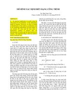
The normal burst, which is the carrier burst of the speech (or data) transmission, is shown
in Figure 8.1. At the beginning of the burst there are three tail bits followed by 57 information
bits. In the middle of the burst we see one (out of eight possible) training sequences of 26-bit
length, preceded and followed by one stealing flag bit, respectively. The training sequence is
used in the receiver as a reference signal for channel estimation and bit synchronization, the
stealing flag bits indicate whether the burst carries user or control data. The next bit block is
made up of the second 57 information bits, followed by three tail bits and a guard time that
corresponds to the duration of 8.25 bits. The guard time is necessary to avoid time slot overlap
caused by the switching of the transmitter’s amplifiers. In total, a burst is built up of 156.25
bits that are transmitted within 576.9 ms. The equalization of a slot is supported by the tail
Parametrization – a Technique for SDR Implementation 237
Figure 8.1 The GSM normal burst
bits. If the maximum likelihood sequence estimation (MLSE) method is used for equaliza-
tion, the tail bits serve for the termination of the sequence estimator in a predefined final state.
Equalization starts from the midamble in such a way that the first data bit block is equalized
from its end, while the second data bit block is equalized from its beginning. Eight bursts fit
into one TDMA frame.
As an example of channel coding in GSM we look at the full rate speech traffic channel
TCH FS. The speech encoder produces 260 bits within 20 ms, but there are differences
between the bits with respect to their importance. Some are more important for the recon-
struction of the speech signal than others. Therefore, the precoded bits are put into an order
according to their importance. In GSM there are two bit classes:
† class 1 and class 1a (with 182 bits in total)
† class 2 (with 78 bits)
The 50 most important bits are assigned to class 1a, encoded by a cyclic block code with three
check bits. The generator polynomial of this systematic cyclic block code is given by
gðxÞ¼x
3
1 x 1 1
All class 1 bits (i.e. also the class 1a bits) are error protected by a convolutional encoder of
rate 1/2. According to the GSM standard the generator polynomials used are
g
1
ðxÞ¼x
4
1 x
3
1 1
and
g
2
ðxÞ¼x
4
1 x
3
1 x 1 1
In total the encoding procedure transforms 182 class 1 data bits (plus three additional check
bits and four bits for the termination of the convolutional code) to 378 code bits. The class 2
bits are transmitted without coding. This results in a total of 456 bits, which corresponds to a
gross data rate of 22.8 kbit/s within a 20 ms speech frame. Besides convolutional and block
coding, interleaving of the traffic data is also performed, implemented via a rearranging
matrix.
8.3.2 Second Generation – IS-136 (DAMPS)
IS-136 is the North American equivalent of GSM. This system is also called digital AMPS
(DAMPS), which indicates that IS-136 is a derivative of the earlier analog advanced mobile
phone service (AMPS) standard. IS-136 specifies the air interface of a digital, terrestrial
cellular mobile radio standard. Table 8.2 shows the most important technical data of this
system. The access is done via FDMA/TDMA. Up- and downlink are separated by FDD. For
speech coding a vector sum excited linear predictive (VSELP) encoder is used.
The modulation mode of IS-136 is
p
/4-DQPSK, i.e. two data bits are transmitted by each
symbol. Therefore a symbol duration of 41.14 ms results, i.e. IS-136 is a system that is in
the border area between broadband and narrowband systems. Unlike GSM, equalization is
not absolutely necessary. In contrast to GMSK, the modulation mode
p
/4-DQPSK is linear.
The envelope of a
p
/4-DQPSK signal is not constant, but due to the phase offset of at least
l
¼
p
/4 for two consecutive symbols the complex envelope avoids zero crossings.
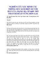
Within one TDMA frame three user signals may be transmitted. A user’s downlink burst is
Software Defined Radio: Enabling Technologies238
shown in Figure 8.2. Data for clock synchronization as well as for channel estimation are
located at the beginning of the burst. In front of the first half of the user data, control data are
inserted. The user data are followed by the colour code, which identifies the base station.
Afterwards, the second half of the data, as well as the attached guard bits for the burst’s
transmission time synchronization, is transmitted.
The VSELP speech encoder provides a data rate of 159 bits every 20 ms. These bits are, as
in GSM, arranged into two classes. There are 77 class 1 and 82 class 2 bits. Class 2 bits are
transmitted without error protection. The 12 most important class 1 bits (class 1a) are
protected by seven bits of a cyclic block code. The corresponding generator polynomial is
gðxÞ¼x
7
1 x
5
1 x
4
1 x
2
1 x 1 1
The class 1 bits as well as the check bits are fed into a terminated convolutional encoder of
rate 1/2 with generator polynomials
Parametrization – a Technique for SDR Implementation 239
Table 8.2 Key air interace parameters of the IS-136 system
Uplink 824–849 MHz
Downlink 869–894 MHz
Channel width 30 kHz
Channel access FDMA/TDMA
Duplex mode FDD/TDD
Users per carrier frequency 3
Speech encoder VSELP
Net speech rate 7.95 kbit/s
Modulation
p
/4-DQPSK
Error correction coding CRC, convolutional
Number of carrier frequencies 832
Bit duration 20.57 ms
Burst duration 6.67 ms
Channel bit rate 48.6 kbit/s
Maximum cell radius 20 km
Figure 8.2 IS-136 downlink burst
g
1
ðxÞ¼x
5
1 x
3
1 x 1 1
and
g
2
ðxÞ¼x
5
1 x
4
1 x
3
1 x
2
1 1
The 77 class 1 bits, seven check bits, and five tail bits (for the termination of the convolutional
encoder) produce 178 code bits at the channel coder’s output. Moreover, there are 82 uncoded
class 2 bits. Related to the speech frame of 20 ms duration, this leads to a gross data rate of
13 kbit/s.
8.3.3 Third Generation – Universal Mobile Telecommunication System (UMTS)
The universal mobile telecommunication system (UMTS), the European version of IMT-
2000, provides two air interfaces, UTRA-FDD and UTRA-TDD. Within the spectral interval
allocated to UMTS there are 12 (duplex) bands for UTRA-FDD and seven bands for UTRA-
TDD. Two out of the seven UTRA-TDD bands are for self-provided applications (similar to
the cordless phone system DECT). The two air interfaces share several similarities: for
example, the bandwidth of 5 MHz, the chip rate of 3.840 Mchip/s, the QPSK-modulation,
as well as the root raised cosine roll-off impulse shaping filter g
s
ðtÞ that employs a roll-off
factor of 0.22. On the other hand, the two air interfaces use different access modes for the
frequency resource. The TDMA component of UTRA-TDD requires synchronization of the
users in the down- as well as in the uplink. Therefore, multiuser detectors [4] that are able to
eliminate multiple access interference (MAI) (which occurs because of nonideal cross-corre-
lation properties of the spreading codes) can be implemented in the base stations. Moreover,
asymmetric data traffic can flow efficiently with TDD. The UTRA-FDD air interface uses
different frequency bands for up- and downlink as well as higher spreading factors. The cell
radii of UTRA-FDD are bigger and the users can move at higher velocities compared with
UTRA-TDD.
UTRA can usually provide several transport channels per user. These transport channels
are separated by time multiplex or physically. A physical channel in UTRA-FDD is defined
by a spreading code, in UTRA-TDD by a spreading code and a time slot on a specific
frequency band. One particular property of UTRA is that many individual data rates are
possible. The different transport channels may employ different data rates and their data may
be transmitted with different error protections. Speech coding (adaptive multirate (AMR)) is
very flexible and leads to data rates between 12.2 and 4.75 kbit/s. For each transport channel,
data can be channel coded, rearranged, and transmitted in sets of transports blocks within
transmission time intervals (TTIs) of 10, 20, 40, or 80 ms (Figure 8.3). The channel data are
adapted to one of the data rates permitted by flexible channel coding and rate adaptation.
First, a systematic block coding for transmission quality control is employed, i.e. to each
transport block a number of CRC bits (between 0 and 24) is appended.
For error correction coding we find the following options:
† convolutional coding with a rate of 1/2 or 1/3, constraint length 8, and maximum code
block length Z ¼ 504 (for example with speech transmission);
† turbo coding with rate 1/3 and maximum code block length Z ¼ 5114 for BERs of at most
10
26
;or
Software Defined Radio: Enabling Technologies240
† no channel coding, if the data to be transmitted are already channel coded by the user, or if
the transmission conditions are ideal.
The number of bits to be transmitted (user data plus CRC) within a TTI is set to the coding
block length N, if it is less than Z; otherwise, the bits have to be divided into several coding
blocks. For termination of the convolutional coding eight zeros are appended at the end of
each coding block. Then a variable block interleaving with column re-arrangement over the
total TTI duration is performed followed by a rate adaptation which depends heavily on the
transmission conditions and upon the cell occupancy. The rate adaptation punctures or
repeats specific bits to achieve the nearest data rate of a physical channel. In the UTRA-
FDD downlink the rate adaptation is applied first, followed by the first interleaving. Then all
transport channels of the user are divided into 10-ms blocks and multiplexed into one single
data stream (coded composite transport channel (CCTrCH)). This data stream is then distrib-
Parametrization – a Technique for SDR Implementation 241
Figure 8.3 UTRA transport channel data
uted to one or several physical channels (dedicated physical channels (DPCHs)), again in
blocks of 10 ms in length, and afterwards rearranged once more by a second block interleaver
with column rearrangement. This means that for UTRA-FDD a CCTrCH of one user is
transformed on to physical channels of an equal transmission rate or spreading factor, respec-
tively. For UTRA-TDD, different physical channels (characterized by time slot and spreading
factor) can contain different numbers of data bits. With the exception of UTRA-FDD uplink
several such CCTrCHs may be built per user and transmitted. The simultaneous transmission
of several physical channels, by using different codes, leads to increased amplitude variations
of the mobile station’s transmission signal in the uplink.
Each physical channel (DPCH) consists of information data (dedicated physical data
channel (DPDCH)) and connection specific control data (dedicated physical control channel
(DPCCH)). The control data contain:
† pilot sequences (with a length of 2, 4, 8, or 16 bits) used for channel estimation and for the
estimation of the carrier to interference ratio C/I for power control;
† feedback information (FBI) bits which are used for transmission of mobile station infor-
mation to the base station and therefore are sent in the uplink only;
† transmit power control (TPC) bits that carry instructions for power control (2, 4, or 8 bits)
† transport format combination indicator (TFCI) bits that give information about the compo-
sition of the data stream (0, 2, or 8 bits).
Pilot sequences are separately sent within each connection. This results in the benefit that
the pilots can be employed for channel estimation even if adaptive antennas are used. More-
over, power control in the downlink and phase control in the uplink become possible too. In
UTRA the transmit power is controlled very quickly, so that even fast fading can be accom-
modated. The distribution of control and data bits for the signals I- and Q-components is
different for the UTRA-FDD up- and downlink. Therefore, we have to discuss them sepa-
rately. Pure control channels like the random access channel (RACH) or the broadcast
channel (BCH) are not further discussed within this text.
The UTRA-FDD downlink’s slot and frame structures are presented in Figure 8.4. A slot is
built up of 2560 chips and therefore its duration is 0.667 ms. Within a slot the DPDCH and the
DPCCH bits are sent successively. The number of bits transmitted by a slot depends on the
spreading factor N
s
, which can take values N
s
¼ 2
k
with k [ {2; 3; …; 9}. Therefore a slot
contains, because of the QPSK modulation, 2 (2560/4) ¼ 1280 control and data bits if the
spreading factor N
s
equals 4. For N
s
¼ 512 the number of control and data bits is 2 (2560/
512) ¼ 10. Because of this concept of variable spreading factors, different data rates can be
transmitted within the same bandwidth of 5 MHz. Accordingly, low data rates are transmitted
with a high spreading factor due to the advantageous properties of the spreading code’s cross
correlation functions (CCFs) and autocorrelation functions (ACFs). The signals are then
resistant against multipath and MAI. For high data rates, low spreading factors apply and
the resistance against multipath and MAI is diminished.
An UTRA frame consists of 15 slots or 38,400 chips and has a duration of 10 ms. A
superframe is composed of 72 UTRA frames. If a single user occupies several DPCHs, the
corresponding DPCCH bits are transmitted only once and the control data are suppressed in
all the other DPCHs.
From Figure 8.5 we see how the modulated and spread transmitter signal sðtÞ is constructed
from the bit stream.
Software Defined Radio: Enabling Technologies242
First, the DPCH bits are distributed on to the I- and Q-branches by serial to parallel
transformation. Afterwards, the data are spread at the chip rate of 3.840 Mchip/s, applying
the same orthogonal variable spreading factor (OVSF) code to the I- and the Q-branch.
Finally, the chip sequence is scrambled a second time by a cell specific spreading sequence.
This procedure is necessary for cell identification and improves the signal’s CCF and ACF
properties. The complex scrambling sequences of a length of 38,400 chips are formed from
sections of Gold sequences. In UMTS the base stations are not synchronized, but each cell has
its own scrambling sequence allocated to it. The cost for the missing base station synchro-
nization is an increased effort at the connection setup, because the cell search can be time
consuming for the mobile, since in total 262,144 scrambling sequences, which are divided
into 512 groups, can be applied for cell identification. The scrambling sequences are deduced
from Gold sequences of length 2
18
2 1, whose generator polynomials are given by
g
1
ðxÞ¼1 1 x
7
1 x
18
and
g
2
ðxÞ¼1 1 x
5
1 x
7
1 x
10
1 x
18
Parametrization – a Technique for SDR Implementation 243
Figure 8.4 The UTRA-FDD downlink structure
Figure 8.5 Construction of the UTRA-FDD transmission signal
The generation of the different Gold sequences is controlled by the initial state of the linear
feedback shift register defined by g
1
ðxÞ. The initial state chosen corresponds to the index of
the generated Gold sequence and can take values between 0 and 262,143. As indicated in
Figure 8.5 the scrambling sequences are complex. If {a
n
; n ¼ 0; …; 2
18
2 1} is a Gold
sequence with index # 262,143, the corresponding complex scrambling sequence of period
38,400 is given by
{c
scr;n
} ¼ {a
n
} 1 j{a
n1131072
}
0 # n # 38; 399
On the downlink the same scrambling sequence is applied for all users, only their separa-
tion is done by the OVSF codes. It can be shown that the family of OVSF codes can be
transformed into the family of Walsh codes by applying bit reversal. All OVSF codes of the
same spreading factor N
s
are mutually orthogonal. For different spreading codes orthogon-
ality is not always guaranteed. Therefore the selection of the OVSF codes, applied in a single
cell, in which user signals of different spreading factors are transmitted, is done by using the
code tree shown in Figure 8.6. Only those codes may be chosen which are not located on the
same path from the root to the outermost branches of the tree. If the codes are chosen by this
procedure, orthogonality is preserved for different spreading factors too.
The UTRA-FDD uplink’s slot and frame structures are presented in Figure 8.7. Here the
control bits (DPCCH) are transmitted in the Q-branch, while the data (DPDCH) bits are sent
in the I-branch (Figure 8.8).
Usually the data rates of the two branches are different in the uplink. To achieve the same
chip rate, the spreading factor 256 is always used in the Q-branch, and for the I-branch
spreading factors N
s
¼ 2
k
; k [ {2; 3; …; 8} are applied, similarly to the downlink. This
means that between 10 and 640 data bits can be transmitted per slot. The assignment of
control and data bits to the Q- and I-branches, respectively, was introduced with regard to the
increased electromagnetic compatibility (EMC). Since the control data have to be transmitted
in every slot, a continuous signal is guaranteed in spite of discontinuous transmission (DTx).
Transmission breaks, which would lead to an on and off switching of the power amplifier, are
Software Defined Radio: Enabling Technologies244
Figure 8.6 The OVSF spreading code tree
avoided. On the downlink, some signals (e.g. the BCCH) are continuously sent. Therefore, no
transmission breaks occur in this case.
Since in the uplink the users are not only separated by the OVSF codes but also by the
scrambling sequences, the same OVSF code may be assigned to several users within the same
cell.
For the uplink the complex scrambling sequences can be chosen from two families: the first
family is constructed of quarternary sequences, 256 chips long, that are generated from the
following polynomials:
g
1
ðxÞ¼1 1 2x 1 x
2
1 3x
3
1 x
5
1 x
8
mod 4
g
2
ðxÞ¼1 1 x 1 x
5
1 x
7
1 x
8
mod 2
and
g
3
ðxÞ¼1 1 x
4
1 x
5
1 x
7
1 x
8
mod 2
Parametrization – a Technique for SDR Implementation 245
Figure 8.7 The UTRA-FDD uplink structure
Figure 8.8 The UTRA-FDD uplink I- and Q-branch
Subsequently, the symbols
a
n,j
ðj ¼ 1; 2; 3Þ, generated by the three polynomials, are
combined:
z
n
¼ð
a
n;1
1 2
a
n; 2
1 2
a
n; 3
Þ mod 4
From the last equation a number z
n
[ {0; 1; 2; 3} results, leading to the complex scram-
bling symbols a
n
, via Table 8.3. These short scrambling sequences are intended to reduce the
computational load in the base station if multiuser detection is applied.
The second family consists of sections of length 38,400, out of Gold sequences {a
n
}of
length 2
25
2 1 and generator polynomials
g
1
ðxÞ¼1 1 x
3
1 x
25
and
g
2
ðxÞ¼1 1 x 1 x
2
1 x
3
1 x
25
The complex scrambling sequences are constructed from the sequence {a
n
}by
{c
scr;n
} ¼ {a
n
ð1 1 jð21Þ
n
a
2½n=211677232
Þ}
0 # n # N 2 1
By using this compound procedure for constructing the scrambling sequence for the uplink,
variations of the modulus of the signal’s complex envelope are avoided. The design of the
scrambling sequences guarantees that within N
s
chips, i.e. within one code period, maximal
one-phase rotation of 1808 can occur; furthermore only phase rotations of 908 and maximal
one 08 rotation appear. Since every user within the network is assigned its own scrambling
sequence, the number of scrambling codes is extremely large; there are 2
24
long as well as 2
24
short scrambling sequences. The most important technical data of the UTRA-FDD air inter-
face are summarized in Table 8.4.
8.4 Parametrization Example
In Section 8.3 we described the air interfaces of the standards GSM, IS-136, and UMTS-FDD
in some detail. Of course, there are substantial differences between the second-generation
(TDMA) standards and the third-generation (CDMA) standard: GSM and IS-136 are on one
side while UMTS-FDD is on the other. Here, spreading in the transmitter and despreading in
the receiver have to be additionally realized.
Software Defined Radio: Enabling Technologies246
Table 8.3 Complex scrambling symbols
z
n
a
n
011 j
1 21 1 j
2 21 2 j
312 j
We will consider the whole signal processing chain, starting with channel coding. There is
only a little difference in the coding algorithms within the set of second-generation standards.
For speech encoding some combination of block coding for the most important speech bits
and convolutional coding for the greater part of the speech bits is applied. For data transmis-
sion a stronger convolutional coding is employed. UTRA-FDD as a third-generation air
interface offers higher data rates of up to 2 Mbit/s and should guarantee a BER of 10
26
for
specific applications. Here, turbo codes [5] are implemented which have to be integrated into
general encoder and decoder structures. For speech coding convolutional codes are used in
UTRA-FDD in general. Since it is not too difficult to find general encoder/decoder structures,
we will concentrate here on the more interesting problem of presenting a general modulator
structure.
8.4.1 A General Modulator
According to Tables 8.1, 8.2, and 8.4, GSM, IS-136, and UTRA-FDD use GMSK,
p
/4-
DQPSK, and QPSK as modulation modes. Additionally, in UTRA-FDD the signal has to
be spread to the chip rate of 3.840 Mchip/s. QPSK and its derivative
p
/4-DQPSK are linear
modulation modes while GMSK is nonlinear [6]. One object of our investigations was to find
a general modulator structure that can process signals of all the standards mentioned above.
Therefore we decided to introduce the linearized version of GMSK into an SDR [7,8].
MSK is a two-valued (linear) frequency shift keying (FSK) modulation with modulation
index h ¼ 0:5. If the rectangular impulse shaping filter of MSK rectð·Þ is replaced by a
gaussian-shaped impulse g
GMSK
ð·Þ, a (nonlinear) GMSK modulation results.
The insertion of the gaussian impulse shaper (Figure 8.9) leads to a bandwidth reduction
but also leads to a (controlled) inter symbol interference (ISI).
Parametrization – a Technique for SDR Implementation 247
Table 8.4 Key air interface parameters of the UTRA-FDD system
Access mode Direct sequence (DS) CDMA
Duplex mode FDD
Chip rate 3.840 Mchip/s
Net data rate 8 kbit/s to 2 Mbit/s
Spreading sequences OVSF codes
Spreading factor 2
k
(k ¼ 2, 3, …, 8); 512 for downlink only
Bandwidth 5 MHz
Channel coding Convolutional, turbo, CRC codes, interleaving
Modulation mode QPSK
Chip impulse shaping filter Root raised cosine, roll-off factor 0.22
Power control Two closed and one open loop, up- and downlink
Specific properties Orthogonal spreading sequences for variable spreading factors
Frame duration 10 ms
Slot duration 0.677 ms
Number of slots per frame 15
The strength of the ISI, or equivalently the bandwidth reduction, depends heavily on the
bandwidth time product BT. The GSM standard defines BT ¼ 0.3, which leads to a reasonable
reduction in bandwidth, but at the same time results in an ISI that has to be equalized in the
receiver. But this may be tolerated since the multipath channel also introduces ISI. Figure
8.10 shows the power spectral densities (PSDs) corresponding to different bandwidth time
products.
In the complex plane the nth symbol d
n
to be transmitted causes a phase variation which has
to be added to the phase variations of the previous symbols. For MSK the signal pointer
rotates exactly by
p
/2 or 2
p
/2 within a symbol clock (Figure 8.11).
For GMSK the complex envelope can be split up into two summands: one represents the
linear, the other represents the nonlinear part of the GMSK signal [9,10]. Moreover, the linear
part contains about 99% of the signal’s energy. Therefore the GMSK signal may be well
Software Defined Radio: Enabling Technologies248
Figure 8.9 Gaussian impulse shaping
Figure 8.10 PSD variation with bandwidth time product
approximated by its linear part, i.e. in a software defined radio the symbols to be transmitted
by a GMSK signal may be pulse shaped with an impulse C
0
ðtÞ that leads to a linear modula-
tion. Using this linear approximation, GMSK signals can be produced by the same linear I/Q
modulator employed for PSK signals. This general modulator structure [3] is shown in Figure
8.12. Construction and parametrization of this modulator are discussed in more detail within
the following paragraphs.
Figure 8.12 shows a general modulator structure that can produce GSM, IS-136, UTRA-
FDD, and even DECT signals. (This structure can be extended to cope with UTRA-TDD and
with cdma2000 signals, which are not shown here for reasons of clarity). For UTRA-FDD the
modulator shown in Figure 8.12 represents the uplink structure.
We should note here that in GSM a differential precoding is necessary. For the bits b
k
[
{0; 1} the precoding is defined by
b
k
¼ b
k
1 b
k21
mod 2:
The initialization with b
21
¼ 1 results from the dummy bits which are sent in GSM before the
first user bit during the starting phase of a GSM burst.
The block Precoder within the functional diagram of the modulator is switched by the
parameters BurstLength and Precoder_On_Off. The parameter BurstLength is used for the
initialization, while with Precoder_On_Off the precoding may be switched off since it is only
required for GSM.
In the next step, the signal is nonreturn to zero (NRZ) coded by the functional block NRZ.
For GSM this leads to d
k
¼ 1 2 2
b
k
.
The functional block NRZ is controlled by the parameter NRZ_On_Off.IfNRZ_On_ Off
equals one, a bit
b
¼ 0 is transformed into
b
0
¼ 1 and
b
¼ 1 into
b
0
¼ 21. For
NRZ_On_Off ¼ 21 the reverse transform results. NRZ_On_Off ¼ 0 indicates that no trans-
form is performed.
Parametrization – a Technique for SDR Implementation 249
Figure 8.11 MSK phase rotation
In the next functional block, MBIT2Symbol, the bits are mapped to complex symbols z
k
.
The modulation mode is chosen by the parameter ModulationNumber, whose function is
specified in Table 8.5.
Since some modulation modes employ memory, an initial state has to be defined. Therefore
the parameter BurstLength is used in this block too. For UTRA-FDD uplink the control data
of the DPDCH are transmitted in the Q-branch and the information data of the first DPDCH
are sent in the I-branch of DPDCH
1
. This modulation may be interpreted as dual QPSK,
where a serial to parallel transform is applied by directing I_Length bits to the I-branch and
Q_Length bits to the Q-branch. The last two parameters are not used for GSM and IS-136. An
other option for UTRA-FDD is to switch more DPDCHs onto the I- and Q-branches. These
channels are indicated in Figure 8.12 by dotted blocks, since this option can only be chosen
with a spreading factor N
s
¼ 4.
For UTRA-FDD, spreading is performed with the next processing step. This function is
controlled by the parameter Spreadingfactor. The spreading sequences are stored and can be
Software Defined Radio: Enabling Technologies250
Figure 8.12 Generalized parametrizable modulator
Table 8.5 MBIT2Symbol parameters
Modulation mode ModulationNumber
GMSK 1
p
/4-DQPSK 2
QPSK 3
Dual QPSK 4
selected by the sequence number. For Spreadingfactor ¼ 1 no spreading takes place. The
following weighting of the data and control channels with the weighting factors w
d
and w
c
,as
well as the complex scrambling, is again performed only for UTRA-FDD.
The next step is the complex impulse shaping, for which different finite impulse response
(FIR) filters can be employed by the parameter Filter_Number (Table 8.6). For GMSK the
(linear) impulse C
0
ðtÞ is used; for PSK modulations root raised cosine roll off filters are
applied.
Table 8.7 presents the parametrization of the general modulator required for GSM, IS-136,
and UTRA-FDD. For UTRA-FDD the BurstLength depends on the spreading factor. In Table
8.7 we used the example Spreadingfactor_I ¼ 8. For the DPCCH, on the other hand,
Spreadingfactor_Q ¼ 256 is always applied.
If, for example, UTRA-TDD should be integrated into this modulator structure, an addi-
tional modulation mode has to be realized in the block MBIT2Symbol (Table 8.5). Moreover,
other scrambling sequences have to be used and finally the complex midamble has to be
inserted.
8.4.2 Effects of GMSK Linearization
The linear approximation of GMSK causes a nonconstant amplitude of the transmitted signal.
Figure 8.13 shows the effect of GMSK linearization to the amplitude sketched in the complex
signal plane for the bandwidth time products BT ¼ 0.5 (DECT) and BT ¼ 0.3 (GSM).
It is evident that the effect of linearization is stronger for BT ¼ 0.3. This can be explained
by the fact that for BT ¼ 0.5 the GMSK modulation itself is ‘almost’ linear and the effect
Parametrization – a Technique for SDR Implementation 251
Table 8.6 Pulse shaping filters
Filter Filter_Number
Main impulse C
0
(t) of linearized GMSK with BT ¼ 0.3 1
Root raised cosine, roll-off factor
a
¼ 0.35 2
Root raised cosine, roll-off factor
a
¼ 0.22 3
Table 8.7 General modulator, parametrization
Parameter GSM IS-136 UTRA-FDD
BurstLength 148 312 330
Precoder_On_Off 10 0
NRZ_On_Off 1121
ModulationNumber 12 4
Spreadingfactor_I 11 8
Spreadingfactor_Q 1 1 256
Filter_Number 12 3
I_Length –– 320
Q_length –– 10
remains minimal in this case. On the other hand, it is the constant envelope that makes GMSK
very attractive for mobile radio, since power efficient C-class amplifiers can be employed in
this case without producing severe intermodulation products.
We can now consider the effects of GMSK linearization if the corresponding signal is
power amplified. For our simulations we used a power amplifier model described in [11] that
well approximates the measured properties of a real Gallium Arsenide field effect transistor
(GaAs FET). Figure 8.14 shows a characteristic AM/AM amplifier of this model.
In Figure 8.15 the PSDs of exact and linearized modulated GMSK signals are compared.
Without nonlinear amplification the PSD of the linearized GMSK signal meets the spectrum
mask given by the GSM standard better than the PSD of the exact GSM signal. If power
Software Defined Radio: Enabling Technologies252
Figure 8.13 Effects of GMSK linearization
Figure 8.14 Characteristic PA amplifier
amplification is applied, the PSD of the linearized GMSK signal closely approximates the
GSM spectrum mask in the region around ^350 kHz distance from the carrier frequency. But
the GSM standard is still met. Since within an SDR the final power amplifier has to meet the
advanced demands of
p
/4-DQPSK and QPSK modulations, the linear GMSK approximation
does not represent a loss in efficiency. For linear power amplifier characteristics we expect
that the PSD of the linearized GMSK signal will meet the GSM standard’s requirements more
closely than for the example amplifier used in our simulations.
Parametrization – a Technique for SDR Implementation 253
Figure 8.15 Comparison of the PSDs for the original and linearized GMSK
Figure 8.16 Effect of linearized GMSK on BER
We now consider the effect which GMSK linearization has on the bit error rate (BER). The
BER heavily depends on the receiver algorithms as well as on the mobile radio channel. For
GSM this channel usually is frequency selective. The GSM channel models acquired by
COST 207 suppose a maximum multipath delay of 20 ms, corresponding to an ISI of six
symbols. Since the equalizer and the channel estimation algorithms usually applied in the
receiver are based on the model of a linearly modulated signal, the application of the linear-
ized GMSK seems to be advantageous with respect to the bit error rate. In this consideration
the nonlinear part of the GSM signal is looked upon as an interference term. The results of this
discussion can be deduced from the simulation results of Figure 8.16.
The simulations were performed using the COST 207 channel models. The differences
between exact and linearized GMSK almost vanish and cannot be detected if channel coding
is applied, since the energy of the nonlinear part of the GMSK signal is very small compared
with the rest. However, it is very important that the linearization of the GMSK signal does not
cause performance degradations.
8.5 Signal Processing Issues
Within this section we consider hardware implementation aspects of SDR. The goal here is
not a detailed discussion; our objective is to consider the applicability of programmable
signal processing components to software defined radios. A wider discussion of hardware
signal processing technology may be found in Chapter 7 by Lund and Honary.
8.5.1 DSP Capabilities and Limitations
We shall restrict ourselves to a discussion of the software defined radio receiver, since the
computational power of a receiver is always larger than that of a transmitter. From the signal
processing viewpoint it is helpful to discriminate between base station receivers, which have
to process several signals simultaneously, and mobile terminal receivers. For a base station
receiver it may be advantageous to digitize the whole system bandwidth at the same time and
to perform the channel selection by digital means (e.g. by a fast Fourier transform (FFT)
receiver). For present purposes, we focus on mobile terminals. In our present example the
total processing requirement of the receiver is determined by UTRA and its channel band-
width of 5 MHz.
The baseband signal processing of a software defined radio has to perform the following
tasks:
† estimation of the channel impulse response
† synchronization
† specific receiver algorithms like RAKE or multiuser detection
† equalization
† demodulation
† burst decomposition
† channel decoding
† source decoding
It makes no sense to concentrate on the efficiency of specific signal processors here, since
within a terminal these devices are integrated into a system environment. Here, we discuss
Software Defined Radio: Enabling Technologies254
some properties that seem to be advantageous in connection with SDRs. This is especially
important with respect to future developments that will require sampling rates of more than
100 Msamples/s, which will have to be processed.
Software defined radios require parallel as well as sequential partitioning of algorithms
such that the necessary computational power can be made available. For this task specific
DSP solutions are on the market. One setup combines a central processing unit (CPU) and a
DSP on the same chip (e.g. Motorola 68356). A different solution is provided by DSPs with
integrated Viterbi processors that can be employed for all applications that need an equalizer
or a convolutional decoder. Of course, sufficiently large memories must be integrated on the
DSP chip to guarantee short access times.
8.5.2 FPGA Capabilities
It is not possible to produce mobile communication terminals or software defined radios
solely using DSPs since they are optimized for sequential programs and only offer restricted
support of parallel processing. In many realizations specific tasks are performed by applica-
tion specific integrated circuits (ASICs). However, ASICs employ hard-wired logic which
does not possess the flexibility necessary for software defined radio implementations.
An FPGA is an array with programmable connections and logic functions, which can be
redefined, even after production. There are two kinds of programmable arrays, programmable
logic devices (PLDs) and FPGAs. Frequently, PLDs implement sums of products of input
signals. Unfortunately all signals then have to be represented in this form (sums of products),
leading to a waste of chip area. On the other hand, FPGAs are built of an array of blocks that
are built of logic blocks with corresponding connections.
Normally, the area occupied by the logic blocks of FPGAs is smaller than that engaged by
PLDs, i.e. the chip area efficiency of FPGAs is higher. A logic block of an FPGA usually
contains look up tables with several data ports and flip-flops for data storage.
For circuit development, hardware description languages like VHDL or Verilog are
presently used. Therefore it is not necessary to worry about internal structures, even though
the processor architectures may be rather complex. Software tools automatically perform
mapping, placing, and routing of electronic circuits on an FPGA. However today, to achieve
the highest efficiency, hard-wiring is also still required.
Configuration of an FPGA typically happens when the system is switched on. During
operation the configuration usually remains fixed. Advanced FPGAs can be reconfigured
dynamically while operating; this is necessary, for example, if a system built with FPGAs
is used alternately as a transmit and receive module.
8.6 Conclusions
In this chapter we have presented the technique of parametrization of the baseband signal
processing for a software defined radio. After a short introduction, the terms ‘digital radio’,
‘software radio’, ‘software defined radio’, and ‘cognitive radio’ were discussed. We then
explored the meaning of adaptability within a software defined radio and explained the
rationale for parametrization of standards. In the next section we presented the most impor-
tant air interface properties of the standards GSM, IS-136, and UTRA-FDD in some detail as
a basis for the development of a general modulator structure that can be used to realize the
Parametrization – a Technique for SDR Implementation 255
different modulation schemes of these standards in a parametrized SDR implementation. We
concluded with a brief consideration of the hardware implementation requirements of SDR.
Parametrization as an SDR technique represents more than simply programming the base-
band signal processor with the appropriate parameters – it represents an important first step
towards the development of new design tools and methodologies for SDR, needed to allow
SDR to transition from its current status of emergent to mainstream technology.
References
[1] Mitola, J., ‘Cognitive Radio, An integrated agent architecture for software defined radio’, PhD Dissertation,
Royal Institute of Technology, Stockholm, Sweden, Department of Teleinformatics, 2000.
[2] Siebert, M., ‘Design of a generic protocol stack for an adaptive terminal’, Proceedings of the 1. Karlsruhe
Workshop on Software Radios, 2000, pp. 31–34.
[3] Wiesler, A., ‘Parametergesteuertes Software Radio fu
¨
r Mobilfunksysteme’, PhD Dissertation, Universita
¨
t
Karlsruhe, Institut fu
¨
r Nachrichtentechnik, 2001.
[4] Verdu, S., Multiuser Detection, Cambridge University Press, Cambridge, 1998.
[5] Heegard, C. and Wicker, S., Turbo Coding, Kluwer, Boston, MA, 1999.
[6] Proakis, J., Digital Communications, 4th Edition, McGraw-Hill, New York, 2000.
[7] Wiesler, A. and Jondral, F., ‘Software radio structure for second generation mobile communication systems’,
Proceedings of the IEEE Vehicular Technology Conference, Vol. 48, May, 1998, pp. 2363–2367.
[8] Wiesler, A., Machauer, R. and Jondral, F., ‘Comparison of GMSK and linear approximation of GMSK for use
in software radio’, Proceedings of the 5th IEEE International Symposium on Spread Spectrum Techniques &
Applications ISSSTA ‘98, Vol. 2/3, September, 1998, pp. 557–560.
[9] Laurent, P.A., ‘Exact and approximate construction of digital phase modulations by superposition of amplitude
modulated pulses (AMP)’, IEEE Transactions in Communications, Vol. 34, 1986, pp. 150–160.
[10] Jung, P., ‘Laurents’ representation of binary digital continuous phase modulated signals with modulation index
1/2 revisited’, IEEE Transactions in Communications, Vol. 42, 1994, pp. 221–224.
[11] Ghorbani, A. and Sheikhan, M., ‘The effect of solid state power amplifiers nonlinearities on MPSK and M-
QAM signal transmission’, Proceedings of the IEE Sixth International Conference on Digital Processing of
Signals in Communications, 1991, pp. 193–197.
Software Defined Radio: Enabling Technologies256