Tài liệu 3D Game Programming All in One- P7 pdf
Bạn đang xem bản rút gọn của tài liệu. Xem và tải ngay bản đầy đủ của tài liệu tại đây (659.79 KB, 30 trang )
■
Organize your code into separate modules, and make sure the module file name is
appropriate for the content, and vice versa.
■
Restrict the number of lines of code you put in a module. Pick a size that suits
you—about 1,000 lines should be near your upper limit.
■
Use descriptive and meaningful variable names.
■
While keeping your variable names descriptive, don't let the names get too long.
■
Never embed tabs in code—use spaces instead. When you view your code later,
you may have different tab settings, and therefore find the code hard to read. Using
spaces guarantees that the visual appearance is consistent. Three spaces for an
indent is a good number.
■
Be consistent in your programming style decisions.
■
Be alert to what programming decisions you make that work well for you, and try
to consistently employ those techniques.
■
Keep a change log of your work so you can keep track of the evolution of your
programs.
■
Use revision control software to manage your program versions.
Moving Right Along
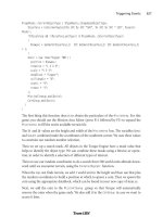
You've now bitten off a fairly big chunk o' stuff. You've learned a new tool—in fact, a new
kind of tool—the programmer's editor. After getting a handle on UltraEdit-32, we looked
at how software does its thing, bringing people and computer hardware together by using
programming languages.
We then went off and started bullying the computer around, using one of those pro-
gramming languages called Torque Script.
Coming up next, we'll delve into the world of 3D programming at a similar level, and dis-
cover the basics of 3D objects, and then how we can manipulate them with Torque Script.
Moving Right Along 87
Team LRN
Please purchase PDF Split-Merge on www.verypdf.com to remove this watermark.
This page intentionally left blank
Team LRN
Please purchase PDF Split-Merge on www.verypdf.com to remove this watermark.
89
3D Programming
Concepts
chapter 3
I
n this chapter we will discuss how objects are described in their three dimensions in
different 3D coordinate systems, as well as how we convert them for use in the 2D
coordinate system of a computer display. There is some math involved here, but don't
worry—I'll do the heavy lifting.
We'll also cover the stages and some of the components of the rendering pipeline—a con-
ceptual way of thinking of the steps involved in converting an abstract mathematical
model of an object into a beautiful on-screen picture.
3D Concepts
In the real world around us, we perceive objects to have measurements in three directions,
or dimensions. Typically we say they have height, width, and depth. When we want to rep-
resent an object on a computer screen, we need to account for the fact that the person
viewing the object is limited to perceiving only two actual dimensions: height, from the
top toward the bottom of the screen, and width, across the screen from left to right.
note
Remember that we will be using the Torque Game Engine to do most of the rendering work
involved in creating our game with this book. However, a solid understanding of the technology
described in this section will help guide you in your decision-making later on when you will be
designing and building your own models or writing code to manipulate those models in real time.
Therefore, it's necessary to simulate the third dimension, depth "into" the screen. We call
this on-screen three-dimensional (3D) simulation of a real (or imagined) object a 3D
model. In order to make the model more visually realistic, we add visual characteristics,
Team LRN
Please purchase PDF Split-Merge on www.verypdf.com to remove this watermark.
such as shading, shadows, and textures. The entire process of calculating the appearance
of the 3D model—converting it to an entity that can be drawn on a two-dimensional (2D)
screen and then actually displaying the resulting image—is called rendering.
Coordinate Systems
When we refer to the dimensional measurement of an object, we use number groups
called coordinates to mark each vertex (corner) of the object. We commonly use the vari-
able names X, Y, and Z to represent each of the three dimensions in each coordinate
group, or triplet. There are different ways to organize the meaning of the coordinates,
known as coordinate systems.
We have to decide which of our variables will represent which dimension—height, width,
or depth—and in what order we intend to reference them. Then we need to decide where
the zero point is for these dimensions and what it means in relation to our object. Once
we have done all that, we will have defined our coordinate system.
When we think about 3D objects, each of the directions is represented by an axis, the infi-
nitely long line of a dimension that passes through the zero point. Width or left-right is
usually the X-axis, height or up-down is usually the Y-axis, and depth or near-far is usu-
ally the Z-axis. Using these constructs, we have ourselves a nice tidy little XYZ-axis system,
as shown in Figure 3.1.
Now, when we consider a single
object in isolation, the 3D space
it occupies is called object space.
The point in object space where
X, Y, and Z are all 0 is normally
the geometric center of an
object. The geometric center of
an object is usually inside the
object. If positive X values are
to the right, positive Y values
are up, and positive Z values are
away from you, then as you can
see in Figure 3.2, the coordinate
system is called left-handed.
The Torque Game Engine uses a slightly different coordinate system, a right-handed one.
In this system, with Y and Z oriented the same as we saw in the left-handed system, X is
positive in the opposite direction. In what some people call Computer Graphics Aerobics,
we can use the thumb, index finger, and middle finger of our hands to easily figure out the
handedness of the system we are using (see Figure 3.3). Just remember that using this
Chapter 3
■
3D Programming Concepts90
Figure 3.1 XYZ-axis system.
Team LRN
Please purchase PDF Split-Merge on www.verypdf.com to remove this watermark.
technique, the thumb is always the Y-axis,
the index finger is the Z-axis, and the mid-
dle finger is the X-axis.
With Torque, we also orient the system in a
slightly different way: The Z-axis is up-
down, the X-axis is somewhat left-right,
and the Y-axis is somewhat near-far (see
Figure 3.4). Actually, somewhat means that
we specify left and right in terms of looking
down on a map from above, with north at
the top of the map. Right and left (positive
and negative X) are east and west, respec-
tively, and it follows that positive Y refers to
north and negative Y to south. Don't forget
that positive Z would be up, and negative Z
would be down. This is a right-handed sys-
tem that orients the axes to align with the
way we would look at the world using a
map from above. By specifying that the zero
point for all three axes is a specific location
on the map, and by using the coordinate
system with the orientation just described,
we have defined our world space.
Now that we have a coordinate system, we
can specify any location on an object or in a
world using a coordinate triplet, such as
(5,Ϫ3,Ϫ2) (see Figure 3.5). By convention,
this would be interpreted as X=5, Y=Ϫ3,
Z=Ϫ2. A 3D triplet is always specified in
XYZ format.
Take another peek at Figure 3.5. Notice anything? That's right—the Y-axis is vertical
with the positive values above the 0, and the Z-axis positive side is toward us. It is still
a right-handed coordinate system. The right-handed system with Y-up orientation is
often used for modeling objects in isolation, and of course we call it object space,as
described earlier. We are going to be working with this orientation and coordinate sys-
tem for the next little while.
3D Concepts 91
Figure 3.2 Left-handed coordinate system with
vertical Y-axis.
Figure 3.3 Right-handed coordinate system
with vertical Y-axis.
Team LRN
Please purchase PDF Split-Merge on www.verypdf.com to remove this watermark.
3D Models
I had briefly touched on the
idea that we can simulate, or
model, any object by defining
its shape in terms of its signifi-
cant vertices (plural for vertex).
Let's take a closer look, by start-
ing with a simple 3D shape,
or primitive—the cube—as
depicted in Figure 3.6.
The cube's dimensions are two
units wide by two units deep
by two units high, or 2ϫ2ϫ2. In this draw-
ing, shown in object space, the geometric
center is offset to a position outside the
cube. I've done this in order to make it clear-
er what is happening in the drawing, despite
my statement earlier that geometric centers
are usually located inside an object. There
are times when exceptions are not only pos-
sible, but necessary—as in this case.
Examining the drawing, we can see the
object's shape and its dimensions quite
clearly. The lower-left-front corner of the
cube is located at the position where X=0,
Y=1, and Z=Ϫ2. As an exercise, take some
time to locate all of the other vertices (cor-
ners) of the cube, and note their coordinates.
If you haven't already noticed on your own,
there is more information in the drawing
than actually needed. Can you see how we
can plot the coordinates by using the
guidelines to find the positions on the axes
of the vertices? But we can also see the
actual coordinates of the vertices drawn
right in the chart. We don't need to do
both. The axis lines with their index tick
marks and values really clutter up the
drawing, so it has become somewhat
accepted in computer graphics to not
Chapter 3
■
3D Programming Concepts92
Figure 3.4 Right-handed coordinate system with vertical Z-
axis depicting world space.
Figure 3.5 A point specified using an XYZ
coordinate triplet.
Figure 3.6 Simple cube shown in a standard
XYZ axis chart.
Team LRN
Please purchase PDF Split-Merge on www.verypdf.com to remove this watermark.
bother with these indices. Instead we try to use the minimum amount of information
necessary to completely depict the object.
We only really need to state whether the object is in object space or world space and indi-
cate the raw coordinates of each vertex. We should also connect the vertices with lines that
indicate the edges.
If you take a look at Figure 3.7 you will see how easy it is to extract the sense of the shape,
compared to the drawing in Figure 3.6. We specify which space definition we are using by the
small XYZ-axis notation. The color code indicates the axis name, and the axis lines are drawn
only for the positive directions. Different modeling tools use different color codes, but in this
book dark yellow (shown as light gray) is the X-axis, dark cyan (medium gray) is the Y-axis,
and dark magenta (dark gray) is the Z-axis. It is also common practice to place the XYZ-axis
key at the geometric center of the model.
Figure 3.8 shows our cube with the geometric
center placed where it reasonably belongs
when dealing with an object in object space.
Now take a look at Figure 3.9. It is obviously
somewhat more complex than our simple
cube, but you are now armed with everything
you need to know in order to understand it. It
is a screen shot of a four-view drawing from
the popular shareware modeling tool
MilkShape 3D, in which a 3D model of a soc-
cer ball was created.
In the figure, the vertices are marked with red
dots (which show as black in the picture), and
the edges are marked with light gray lines. The
axis keys are visible, although barely so in some views
because they are obscured by the edge lines. Notice the grid
lines that are used to help with aligning parts of the model.
The three views with the gray background and grid lines are
2D construction views, while the fourth view, in the lower-
right corner, is a 3D projection of the object. The upper-left
view looks down from above, with the Y-axis in the vertical
direction and the X-axis in the horizontal direction. The Z-
axis in that view is not visible. The upper-right view is look-
ing at the object from the front, with the Y-axis vertical
3D Concepts 93
Figure 3.7 Simple cube with reduced XYZ-
axis key.
Figure 3.8 Simple cube with
axis key at geometric center.
Team LRN
Please purchase PDF Split-Merge on www.verypdf.com to remove this watermark.
and the Z-axis horizontal; there
is no X-axis. The lower-left
view shows the Z-axis vertically
and the X-axis horizontally
with no Y-axis. In the lower-
right view, the axis key is quite
evident, as its lines protrude
from the model.
3D Shapes
We've already encountered
some of things that make up
3D models. Now it's time to
round out that knowledge.
As we've seen, vertices define
the shape of a 3D model. We
connect the vertices with lines
known as edges. If we connect
three or more vertices with edges to create a closed figure,
we've created a polygon. The simplest polygon is a trian-
gle. In modern 3D accelerated graphics adapters, the
hardware is designed to manipulate and display millions
and millions of triangles in a second. Because of this
capability in the adapters, we normally construct our
models out of the simple triangle polygons instead of the
more complex polygons, such as rectangles or pentagons
(see Figure 3.10).
By happy coincidence, triangles are more than up to the
task of modeling complex 3D shapes. Any complex poly-
gon can be decomposed into a collection of triangles,
commonly called a mesh (see Figure 3.11).
The area of the model is known as the surface. The polyg-
onal surfaces are called facets—or at least that is the tra-
ditional name. These days, they are more commonly
called faces. Sometimes a surface can only be viewed
from one side, so when you are looking at it from its
"invisible" side, it's called a hidden surface,or hidden face.
A double-sided face can be viewed from either side. The
edges of hidden surfaces are called hidden lines. With
Chapter 3
■
3D Programming Concepts94
Figure 3.9 Screen shot of sphere model.
Figure 3.10 Polygons of
varying complexity.
Figure 3.11 Polygons
decomposed into triangle meshes.
Team LRN
Please purchase PDF Split-Merge on www.verypdf.com to remove this watermark.
most models, there are faces on the back side
of the model, facing away from us, called
backfaces (see Figure 3.12). As mentioned,
most of the time when we talk about faces in
game development, we are talking about tri-
angles, sometimes shortened to tris.
Displaying 3D Models
After we have defined a model of a 3D object
of interest, we may want to display a view of it.
The models are created in object space, but to
display them in the 3D world, we need to con-
vert them to world space coordinates. This
requires three conversion steps beyond the actual creation of the model in object space.
1. Convert to world space coordinates.
2. Convert to view coordinates.
3. Convert to screen coordinates.
Each of these conversions involves mathematical operations performed on the object's
vertices.
The first step is accomplished by the process called transformation. Step 2 is what we call
3D rendering. Step 3 describes what is known as 2D rendering. First we will examine what
the steps do for us, before getting into the gritty details.
Transformation
This first conversion, to world space coordinates, is necessary because we have to place our
object somewhere! We call this conversion transformation. We will indicate where by
applying transformations to the object: a scale operation (which controls the object's
size), a rotation (which sets orientation), and a translation (which sets location).
World space transformations assume that the object starts with a transformation of
(1.0,1.0,1.0) for scaling, (0,0,0) for rotation, and (0,0,0) for translation.
Every object in a 3D world can have its own 3D transformation values, often simply called
transforms, that will be applied when the world is being prepared for rendering.
tip
Other terms used for these kinds of XYZ coordinates in world space are
Cartesian coordinates
,or
rectangular coordinates
.
Displaying 3D Models 95
Figure 3.12 The parts of a 3D shape.
Team LRN
Please purchase PDF Split-Merge on www.verypdf.com to remove this watermark.
Scaling
We scale objects based upon a triplet
of scale factors where 1.0 indicates a
scale of 1:1.
The scale operation is written simi-
larly to the XYZ coordinates that are
used to denote the transformation,
except that the scale operation shows
how the size of the object has
changed. Values greater than 1.0 indi-
cate that the object will be made larger, and values less than 1.0 (but greater than 0) indi-
cate that the object will shrink.
For example, 2.0 will double a given dimension, 0.5 will halve it, and a value of 1.0 means
no change. Figure 3.13 shows a scale operation performed on a cube in object space. The
original scale values are (1.0,1.0,1.0). After scaling, the cube is 1.6 times larger in all three
dimensions, and the values are (1.6,1.6,1.6).
Rotation
The rotation is written in the same way that XYZ coordinates are used to denote the trans-
formation, except that the rotation shows how much the object is rotated around each of
its three axes. In this book, rotations will be specified using a triplet of degrees as the unit
of measure. In other contexts, radians might be the unit of measure used. There are also
other methods of representing rotations that are used in more complex situations, but this
is the way we'll do it in this book. Figure 3.14 depicts a cube being rotated by 30 degrees
around the Y-axis in its object space.
It is important to realize that the order of the rotations applied to the object matters a
great deal. The convention we will use is the roll-pitch-yaw method, adopted from the
aviation community. When we rotate the object, we roll it around its longitudinal (Z)
axis. Then we pitch it around the
lateral (X) axis. Finally, we yaw it
around the vertical (Y) axis.
Rotations on the object are applied
in object space.
If we apply the rotation in a differ-
ent order, we can end up with a
very different orientation, despite
having done the rotations using the
same values.
Chapter 3
■
3D Programming Concepts96
Figure 3.13 Scaling.
Figure 3.14 Rotation.
Team LRN
Please purchase PDF Split-Merge on www.verypdf.com to remove this watermark.
Translation
Translation is the simplest of the transformations and the first that is applied to the object
when transforming from object space to world space. Figure 3.15 shows a translation
operation performed on an object. Note that the vertical axis is dark gray. As I said earli-
er, in this book, dark gray represents the Z-axis. Try to figure out what coordinate system
we are using here. I'll tell you later in the chapter. To translate an object, we apply a vec-
tor to its position coordinates. Vectors can be specified in different ways, but the notation
we will use is the same as the XYZ triplet, called a vector triplet. For Figure 3.15, the vec-
tor triplet is (3,9,7). This indicates that the object will be moved three units in the posi-
tive X direction, nine units in the
positive Y direction, and seven
units in the positive Z direction.
Remember that this translation is
applied in world space, so the X
direction in this case would be east-
ward, and the Z direction would be
down (toward the ground, so to
speak). Neither the orientation nor
the size of the object is changed.
Full Transformation
So now we roll all the
operations together. We
want to orient the cube a
certain way, with a cer-
tain size, at a certain
location. The transfor-
mations applied are scale
(s)=1.6,1.6,1.6, followed
by rotation (r)=0,30,0,
and then finally transla-
tion (t)=3,9,7. Figure
3.16 shows the process.
Displaying 3D Models 97
Figure 3.15 Translation.
Figure 3.16 Fully transforming the cube.
Team LRN
Please purchase PDF Split-Merge on www.verypdf.com to remove this watermark.
note
The order that we use to apply the transformations is important. In the great majority of cases, the
correct order is scaling, rotation, and then translation. The reason is that different things happen
depending on the order.
You will recall that objects are
created in object space, then
moved into world space. The
object's origin is placed at the
world origin. When we rotate the
object, we rotate it around the
appropriate axes with the origin
at (0,0,0), then translate it to its
new position.
If you translate the object first,
then rotate it (which is still going
to take place around (0,0,0), the
object will end up in an entirely
different position as you can see
in Figure 3.17.
Rendering
Rendering is the process of converting the 3D mathematical model of an object into an
on-screen 2D image. When we render an object, our primary task is to calculate the
appearance of the different faces of the object, convert those faces into a 2D form, and
send the result to the video card, which will then take all the steps needed to display the
object on your monitor.
We will take a look at several different techniques for rendering, those that are often used
in video game engines or 3D video cards. There are other techniques, such as ray-casting,
that aren't in wide use in computer games—with the odd exception, of course—that we
won't be covering here.
In the previous sections our simple cube model had colored faces. In case you haven't
noticed (but I'm sure you did notice), we haven't covered the issue of the faces, except
briefly in passing.
A face is essentially a set of one or more contiguous co-planar adjacent triangles; that is,
when taken as a whole, the triangles form a single flat surface. If you refer back to Figure
3.12, you will see that each face of the cube is made with two triangles. Of course, the faces
are transparent in order to present the other parts of the cube.
Chapter 3
■
3D Programming Concepts98
Figure 3.17 Faces on an irregularly shaped object.
Team LRN
Please purchase PDF Split-Merge on www.verypdf.com to remove this watermark.
Flat Shading
Figure 3.18 provides an example of various face config-
urations on an irregularly shaped object. Each face is
presented with a different color (which are visible as dif-
ferent shades). All triangles with the label A are part of
the same face; the same applies to the D triangles. The
triangles labeled B and C are each single-triangle faces.
When we want to display 3D objects, we usually use
some technique to apply color to the faces. The sim-
plest method is flat shading, as used in Figure 3.17. A
color or shade is applied to a face, and a different color
or shade is applied to adjacent faces so that the user
can tell them apart. In this case, the shades were select-
ed with the sole criterion being the need to distinguish one face from the other.
One particular variation of flat shading is called Z-flat shading. The basic idea is that the
farther a face is from the viewer, the darker or lighter the face.
Lambert Shading
Usually color and shading are applied in a manner
that implies some sense of depth and lighted space.
One face or collection of faces will be lighter in shade,
implying that the direction they face has a light source.
On the opposite side of the object, faces are shaded to
imply that no light, or at least less light, reaches those
faces. In between the light and dark faces, the faces are
shaded with intermediate values. The result is a shad-
ed object where the face shading provides information
that imparts a sense of the object in a 3D world,
enhancing the illusion. This is a form of flat shading
known as lambert shading (see Figure 3.19).
Gouraud Shading
A more useful way to color or shade an object
is called gouraud shading. Take a look at Figure
3.20. The sphere on the left (A) is flat shaded,
while the sphere on the right (B) is gouraud
shaded. Gouraud shading smoothes the colors
by averaging the normals (the vectors that
indicate which way surfaces are facing) of the
Displaying 3D Models 99
Figure 3.18 Faces on an
irregularly shaped object.
Figure 3.19 Lambert-shaded
object.
Figure 3.20 Flat-shaded (A) and gouraud-
shaded (B) spheres.
Team LRN
Please purchase PDF Split-Merge on www.verypdf.com to remove this watermark.
vertices of a surface. The normals are used to modify the color value of all the pixels in a face.
Each pixel's color value is then modified to account for the pixel's position within the face.
Gouraud shading creates a much more natural appearance for the object, doesn't it?
Gouraud shading is commonly used in both software and hardware rendering systems.
Phong Shading
Phong shading is a much more sophisticated—and computation-intensive—technique for
rendering a 3D object. Like gouraud shading, it calculates color or shade values for each
pixel. Unlike gouraud shading (which uses only the vertices' normals to calculate average
pixel values), phong shading computes additional normals for each pixel between vertices
and then calculates the new color values. Phong shading does a remarkably better job (see
Figure 3.21), but at a substantial cost.
Phong shading requires a great deal of processing for even a simple scene, which is why
you don't see phong shading used much in real-time 3D games where frame rate perfor-
mance is important. However, there are games made where frame rate is not as big an
issue, in which case you will often find phong shading used.
Fake Phong Shading
There is a rendering technique that looks almost as
good as phong shading but can allow fast frame
rates. It's called fake phong shading, or sometimes
fast phong shading, or sometimes even phong approx-
imation rendering. Whatever name it goes by, it is not
phong rendering. It is useful, however, and does
indeed give good performance.
Fake phong shading basically employs a bitmap,
which is variously known as a phong map,a high-
light map,a shade map,or alight map. I'm sure
there are other names for it as well. In any event,
the bitmap is nothing more than a generic template
of how the faces should be illuminated (as shown in
Figure 3.22).
As you can tell by the nomenclature, there is no real con-
sensus about fake phong shading. There are also several
different algorithms used by different people. This diver-
sity is no doubt the result of several people independent-
ly arriving at the same general concept at roughly the
same time—all in search of better performance with
high-quality shading.
Chapter 3
■
3D Programming Concepts100
Figure 3.21 Phong-shaded sphere.
Figure 3.22 Example of a
fake phong highlight map.
Team LRN
Please purchase PDF Split-Merge on www.verypdf.com to remove this watermark.
Texture Mapping
Texture mapping is covered in more detail in Chapters 8
and 9. For the sake of completeness, I'll just say here that
texture mapping an object is something like wallpapering
a room. A 2D bitmap is "draped" over the object, to
impart detail and texture upon the object, as shown in
Figure 3.23.
Texture mapping is usually combined with one of the
shading techniques covered in this chapter.
Shaders
When the word is used alone, shaders refers to shader programs that are sent to the video
hardware by the software graphics engine. These programs tell the video card in great detail
and procedure how to manipulate vertices or pixels, depending on the kind of shader used.
Traditionally, programmers have had limited control over what happens to vertices and
pixels in hardware, but the introduction of shaders allowed them to take complete control.
Vertex shaders, being easier to implement, were first out of the starting blocks. The shad-
er program on the video card manipulates vertex data values on a 3D plane via mathe-
matical operations on an object's vertices. The operations affect color, texture coordinates,
elevation-based fog density, point size, and spatial orientation.
Pixel shaders are the conceptual siblings of vertex shaders, but they operate on each dis-
crete viewable pixel. Pixel shaders are small programs that tell the video card how to
manipulate pixel values. They rely on data from vertex shaders (either the engine-specif-
ic custom shader or the default video card shader function) to provide at least triangle,
light, and view normals.
Shaders are used in addition to other rendering operations, such as texture mapping.
Bump Mapping
Bump mapping is similar to texture mapping. Where texture maps add detail to a shape,
bump maps enhance the shape detail. Each pixel of the bump map contains information
that describes aspects of the physical shape of the object at the corresponding point, and
we use a more expansive word to describe this—the texel. The name texel derives from tex-
ture pixel.
Bump mapping gives the illusion of the presence of bumps, holes, carving, scales, and
other small surface irregularities. If you think of a brick wall, a texture map will provide
the shape, color, and approximate roughness of the bricks. The bump map will supply a
Displaying 3D Models 101
Figure 3.23 Texture-mapped
and gouraud-shaded cube.
Team LRN
Please purchase PDF Split-Merge on www.verypdf.com to remove this watermark.
detailed sense of the roughness of the brick, the mortar, and other details. Thus bump
mapping enhances the close-in sense of the object, while texture mapping enhances the
sense of the object from farther away.
Bump mapping is used in conjunction with most of the other rendering techniques.
Environment Mapping
Environment mapping is similar to texture mapping, except that it is used to represent
effects where environmental features are reflected in the surfaces of an object. Things like
chrome bumpers on cars, windows, and other shiny object surfaces are prime candidates
for environment mapping.
Mipmapping
Mipmapping is a way of reducing the amount of computation
needed to accurately texture-map an image onto a polygon.
It's a rendering technique that tweaks the visual appearance of
an object. It does this by using several different textures for the
texture-mapping operations on an object. At least two, but
usually four, textures of progressively lower resolution are
assigned to any given surface, as shown in Figure 3.24. The
video card or graphics engine extracts pixels from each
texture, depending on the distance and orientation of the
surface compared to the view screen.
In the case of a flat surface that recedes away from the
viewer into the distance, for pixels on the nearer parts of
the surface, pixels from the high-resolution texture are
used (see Figure 3.25). For the pixels in the middle dis-
tances, pixels from the medium-resolution textures are
used. Finally, for the faraway parts of the surface, pixels
from the low-resolution texture are used.
tip
Anti-aliasing
is a software technique used in graphics display systems to make curved and diago-
nal lines appear to be continuous and smooth. On computer monitors the pixels themselves aren't
curved, but collectively they combine together to represent curves. Using pixels within polygon
shapes to simulate curves causes the edges of objects to appear jagged. Anti-aliasing, the tech-
nique for smoothing out these jaggies, or aliasing, usually takes the form of inserting intermediate-
colored pixels along the edges of the curve. The funny thing is, with textual displays this has the
paradoxical effect of making text blurrier yet more readable. Go figure!
Chapter 3
■
3D Programming Concepts102
Figure 3.24 Mipmap
textures for a stone surface.
Figure 3.25 Receding mipmap
textures on a stone surface.
Team LRN
Please purchase PDF Split-Merge on www.verypdf.com to remove this watermark.
Scene Graphs
In addition to knowing how to construct and render 3D objects, 3D engines need to know
how the objects are laid out in the virtual world and how to keep track of changes in sta-
tus of the models, their orientation, and other dynamic information. This is done using a
mechanism called a scene graph, a specialized form of a directed graph. The scene graph
maintains information about all entities in the virtual world in structures called nodes.
The 3D engine traverses this graph, examining each node one at a time to determine how
to render each entity in the world. Figure 3.26 shows a simple seaside scene with its scene
graph. The nodes marked by ovals are group nodes, which contain information about
themselves and point to other nodes. The nodes that use rectangles are leaf nodes. These
nodes contain only information about themselves.
Note that in the seaside scene graph, not all of the nodes contain all of the information
that the other nodes have about themselves.
Many of the entities in a scene don't even need to be rendered. In a scene graph, a node
can be anything. The most common entity types are 3D shapes, sounds, lights (or light-
ing information), fog and other environmental effects, viewpoints, and event triggers.
Displaying 3D Models 103
Figure 3.26 Simple scene graph.
Team LRN
Please purchase PDF Split-Merge on www.verypdf.com to remove this watermark.
When it comes time to render the scene, the Torque Engine will "walk" through the nodes
in the tree of the scene graph, applying whatever functions to the node that are specified.
It then uses the node pointers to move on to the next node to be rendered.
3D Audio
Audio and sound effects are used to heighten the sense of realism in a game. There are
times when the illusion is greatly enhanced by using position information when generat-
ing the sound effects. A straightforward example would be the sound generated by a near-
by gunshot. By calculating the amplitude—based on how far away the shot occurred—
and the direction, the game software can present the sound to a computer's speakers in a
way that gives the player a strong sense of where the shot occurred. This effect is even bet-
ter if the player is wearing audio headphones. The player then has a good sense of the
nature of any nearby threat and can deal with it accordingly—usually by massive applica-
tion of return fire.
The source location of a game sound is tracked and managed in the same way as any other
3D entity via the scene graph.
Once the game engine has decided that the sound has been triggered, it then converts
the location and distance information of the sound into a stereo "image" of the sound,
with appropriate volumes and balance for either the right or left stereo channel. The
methods used to perform these calculations are much the same as those used for 3D
object rendering.
Audio has an additional set of complications—things like fade and drop-off or cutoff.
3D Programming
With the Torque Engine, most of the really grubby low-level programming is done for
you. Instead of writing program code to construct a 3D object, you use a modeling tool
(which we cover in later chapters) to create your object and a few lines of script code to
insert the object in a scene. You don't even need to worry about where in the scene graph
the object should be inserted—Torque handles that as well, through the use of informa-
tion contained in the datablocks that you define for objects.
Even functions like moving objects around in the world are handled for us by Torque, sim-
ply by defining the object to be of a certain class and then inserting the object appropriately.
The kinds of objects we will normally be using are called shapes. In general, shapes in
Torque are considered to be dynamic objects that can move or otherwise be manipulated
by the engine at run time.
There are many shape classes; some are fairly specific, like vehicles, players, weapons, and
projectiles. Some are more general-purpose classes, like items and static shapes. Many of
Chapter 3
■
3D Programming Concepts104
Team LRN
Please purchase PDF Split-Merge on www.verypdf.com to remove this watermark.
the classes know how their objects should respond to game stimuli and are able to respond
in the game with motion or some other behavior inherent to the object's class definition.
Usually, you will let the game engine worry about the low-level mechanics of moving your
3D objects around the game world. However, there will probably be times while creating a
game that you are going to want to cause objects to move in some nonstandard way—some
method not defined by the class definition of the object. With Torque, this is easy to do!
Programmed Translation
When an object in 3D world space moves, it is translating its position, in a manner simi-
lar to that shown earlier in the discussion about transformations.
You don't, however, absolutely need to use the built-in classes to manipulate shapes in
your game world. For example, you can write code to load in an Interior (a class of objects
used for structures like buildings) or an Item (a class of objects used for smaller mobile
and static items in a game world, like signs, boxes, and powerups). You can then move that
object around the world any way you like.
You can also write code to monitor the location of dynamic shapes that are moving
around in the world, detect when they reach a certain location, and then arbitrarily move,
or teleport, those objects to some other location.
Simple Direct Movement
What we are going to do is select an object in a 3D scene in Torque and then move it from
one location to another using some script instructions entered directly into the game con-
sole. The first step is to identify the object.
1. In the 3DGPAi1 folder locate the Run Chapter 3 shortcut and double-click it to
launch the demo.
2. Click Start.
3. Using the mouse, turn your player-character to the left or right a bit, if necessary,
until you have a good view of the pyramid.
4. Press F11. Torque's built-in World Editor will appear. As you move your cursor
over the scene, you'll notice it change to a hand icon.
5. Click the hand on the pyramid to select it.
6. Move the cursor over to the right side, and click once on the plus sign to the left of
the words "MissionGroup - SimGroup". You will see the list expand, and one of the
entries, of the type InteriorInstance, will be highlighted. Take note of the number
to the left, which is the object's instance ID. See Figure 3.27 for help, if necessary.
The ID I get from the figure is 1359; your result should be the same.
3D Programming 105
Team LRN
Please purchase PDF Split-Merge on www.verypdf.com to remove this watermark.
7. Press the Tilde ("~")
key, and the console
will pop open. The
console interface
allows us to directly
type in program
code and get
immediate results.
8. In the console
window, type
echo(1353.get-
Transform() ); and
then press the Enter
key. Don't forget to
include the semi-
colon at the end of
the line before you
press the Enter key.
You should get a result like 49.2144 -66.1692 0.4 0 0 -1 9.74027, which is the trans-
form of the pyramid. The first three numbers are the XYZ coordinates of the geo-
metric center of the pyramid. The next three are the axis normals, which in this case
indicates that the Z-axis is pointing straight up. The final value indicates how much
rotation is applied around the rotation axes. We'll look at rotation in more detail a
little later. Here, the rotation amount (in degrees) is applied to only the Z-axis.
9. In the console window, type 1353.setTransform("0 0 190 0 0 1 0"); and then press
the Enter key.
10. Press the Escape key to remove the console window, and take a look. You will
notice that the pyramid has moved.
11. Take the next several minutes to experiment with different transforms. Try rotating
the pyramid around different axes or several axes at the same time.
12. When you are done, press the Tilde key to exit the console window, press Escape to
exit the World Editor, and then press Escape one more time to exit the game.
tip
In the little exercise in the "Simple Direct Movement" section, you saw a command that looked like
this:
echo(1353.getTransform() );
. The number 1353 is an object ID, and the
getTransform()
part is what is called a
method
of that object. A method is a function that belongs to a specific
object
class
. We'll cover these topics in more detail in a later chapter.
Chapter 3
■
3D Programming Concepts106
Figure 3.27 Finding the pyramid object's instance ID.
Team LRN
Please purchase PDF Split-Merge on www.verypdf.com to remove this watermark.
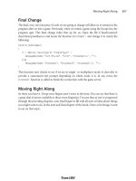
Programmed Movement
Now we are going to explore how we can move things in the 3D world using program
code. We are going to use the Item class to create an object based on a model of a stylized
heart, insert the object in the game world, and then start it slowly moving across the ter-
rain—all using Torque Script.
Something to know about the Item class is that Torque defines it as being affected by grav-
ity. So if we insert the object into the scene at some distance above the ground level of the
terrain, the object will actually fall to the ground—a little more slowly than it would in the
real world, but what the hey! It's a game, after all. Anyway, this also means that we have to
specify a mass and a friction drag value in order to prevent the item from sliding down
hills if it lands on a slope.
Okay, now—so on to the program. Type the following code module into a file and save
the file as 3DGPAi1\CH3\moveshape.cs.
// ========================================================================
// moveshape.cs
//
// This module contains the definition of a test shape, which uses
// a model of a stylized heart. It also contains functions for placing
// the test shape in the game world and moving the shape.
// ========================================================================
datablock ItemData(TestShape)
//
// Definition of the shape object
//
{
// Basic Item properties
shapeFile = "~/data/shapes/items/heart.dts";
mass = 1; //we give the shape mass and
friction = 1; // friction to stop the item from sliding
// down hills
};
function InsertTestShape()
//
// Instantiates the test shape, then inserts it
// into the game world roughly in front of
// the player's default spawn location.
//
{
3D Programming 107
Team LRN
Please purchase PDF Split-Merge on www.verypdf.com to remove this watermark.
// An example function which creates a new TestShape object
%shape = new Item() {
datablock = TestShape;
rotation = "0 0 1 0"; // initialize the values
// to something meaningful
};
MissionCleanup.add(%shape);
// Player setup
%shape.setTransform("-90 -2 20 0 0 1 0");
echo("Inserting Shape " @ %shape);
return %shape;
}
function MoveShape(%shape, %dist)
//
// moves the %shape by %dist amount
//
{
%xfrm = %shape.getTransform();
%lx = getword(%xfrm,0); // get the current transform values
%ly = getword(%xfrm,1);
%lz = getword(%xfrm,2);
%lx += %dist; // adjust the x axis position
%shape.setTransform(%lx SPC %ly SPC %lz SPC "0 0 1 0");
}
function DoMoveTest()
//
// a function to tie together the instantiation
// and the movement in one easy to type function
// call.
//
{
%ms = InsertTestShape();
MoveShape(%ms,15);
}
In this module there are three functions and a datablock definition. A datablock is a con-
struct that is used to organize properties for objects together in a way that is important for
the server. We will cover datablocks in more detail in a later chapter. The datablock begins
with the line
datablock ItemData(TestShape)
—it specifies static properties of the Item class
that can't be changed while the game is running. The most important part of the preceding
Chapter 3
■
3D Programming Concepts108
Team LRN
Please purchase PDF Split-Merge on www.verypdf.com to remove this watermark.
datablock is the
shapeFile
property, which tells Torque where to find the model that will be
used to represent the object. The mass and friction values, as mentioned previously, prevent
the item from sliding down hills because of the pernicious tug of gravity.
The function
InsertTestShape()
creates a new instance of
TestShape
with the call to
new
Item().
It specifies the
TestShape
datablock, defined earlier, and then sets the object's rota-
tion to some sensible values.
Next,
MissionCleanup.add(%shape)
; adds the shape instance to a special mission-related
group maintained by Torque. When the mission ends, objects assigned to this group are
deleted from memory (cleaned up) before a new mission is started.
After that, the program sets the initial location of the object by setting the transform.
Next, the
echo
statement prints the shape's handle to the console.
Finally, the shape's handle (ID number) is returned from the function. This allows us to
save the handle in a variable when we call this function, so that we can refer to this same
item instance at a later time.
The function
MoveShape
accepts a shape handle and a distance as arguments, and uses these
to move whatever shape the handle indicates.
First, it gets the current position of the shape using the
%shape.getTransform()
method of
the Item class.
Next, the program employs the
getword()
function to extract the parts of the transform
string that are of interest and store them in local variables. We do this because, for this
particular program, we want to move the shape in the X-axis. Therefore, we strip out all
three axes and increment the X value by the distance that the object should move. Then
we prepend all three axis values to a dummy rotation and set the item's transform to be
this new string value. This last bit is done with the
%shape.setTransform()
statement.
The
DoMoveTest()
function is like a wrapper folded around the other functions. When we call
this function, first it inserts the new instance of the shape object using the
InsertTestShape()
function and saves the handle to the new object in the variable
%ms
. It then calls the
MoveShape()
function, specifying which shape to move by passing in the handle to the shape
as the first argument and also indicating the distance with the second argument.
To use the program, follow these steps:
1. Make sure you've saved the file as 3DGPAi1\CH3\moveshape.cs.
2. Run the Chapter 3 demo using the shortcut in the 3DGPAi1 folder.
3. Press the Start button when the CH3 demo screen comes up.
4. Make sure you don't move your player-character after it spawns into the game
world.
3D Programming 109
Team LRN
Please purchase PDF Split-Merge on www.verypdf.com to remove this watermark.
5. Bring up the console window by pressing the Tilde key.
6. Type in the following, and press Enter after the semicolon:
exec("CH3/moveshape.cs");
You should get a response in the console window similar to this:
Compiling CH3/moveshape.cs
Loading compiled script CH3/moveshape.cs.
This means that the Torque Engine has compiled your program and then loaded it
into memory. The datablock definition and the three functions are in memory,
waiting with barely suppressed anticipation for your next instruction.
tip
About those slashes… You've probably noticed that when you see the file names and paths writ-
ten out, the back slash ("\") is used, and when you type in those same paths in the console win-
dow, the forward slash ("/") is used. This is not a mistake. Torque is a cross-platform program that
is available for Macintosh and Linux as well as Windows. It's only on Windows-based systems that
back slashes are used—everyone else uses forward slashes.
Therefore, the back slashes for Windows-based paths are the exception here. Just thought I'd clear
that up!
7. Type the following into the console window:
$tt = InsertTestShape();
You should see the following response:
Inserting Shape 1388
The number you get may be different—that's not an issue. But it will probably be
the same. Take note of the number.
You also may see a warning about not locating a texture—that's of no importance
here either.
8. Close the console window. You should see a heart on the ground in front of your
player.
9. Type the following into the console:
echo($tt);
Torque will respond by printing the contents of the variable
$tt
to the console
window. It should be the same number that you got as a response after using the
InsertTestShape
instruction above.
10. Type the following into the console:
MoveShape(%tt,50);
Chapter 3
■
3D Programming Concepts110
Team LRN
Please purchase PDF Split-Merge on www.verypdf.com to remove this watermark.
11. Press the Tilde key to close the console window. You should see the heart move
away from you to the left.
You should be familiar with opening and closing the console window by now, so I
won't bother explaining that part in the instruction sequences anymore.
12. Now, type this into the console, and close the console quickly afterward:
DoMoveTest();
What you should see now is the heart dropping from the air to the ground; it then
moves away just like the first heart, except not as far this time.
The reason why the heart drops from the air is because the object's initial location was set
in the
InsertTestShape()
function to be
-90 -2 20
, where the Z value is set to 20 units up.
As mentioned earlier, Torque will automatically make objects of the Item class fall under
gravity until they hit something that stops the fall. If you don't close the console window
quickly enough, you won't see it fall.
Go ahead and experiment with the program. Try moving the item through several axes at
once, or try changing the distance.
Programmed Rotation
As you've probably figured out already, we can rotate an object programmatically (or
directly, for that matter) using the same
setTransform()
method that we used to translate
an object.
Type the following program and save it as 3DGPAi1\CH3\turnshape.cs.
// ========================================================================
// turnshape.cs
//
// This module contains the definition of a test shape.
// It contains functions for placing
// the test shape in the game world and rotating the shape
// ========================================================================
datablock ItemData(TestShape)
//
// Definition of the shape object
//
{
// Basic Item properties
shapeFile = "~/data/shapes/items/heart.dts";
mass = 1; //we give the shape mass and
friction = 1; // friction to stop the item from sliding
3D Programming 111
Team LRN
Please purchase PDF Split-Merge on www.verypdf.com to remove this watermark.