Tài liệu Cryptographic Algorithms on Reconfigurable Hardware- P9 docx
Bạn đang xem bản rút gọn của tài liệu. Xem và tải ngay bản đầy đủ của tài liệu tại đây (1.45 MB, 30 trang )
7.6 Recent Hardware Implementations of Hash Functions 219
4x-unrolled. Those architectures optimize time performances by combining
pipehning and unrolHng techniques.
In
[333],
a common architecture is customized for three SHA2 algorithms:
SHA2 (256), SHA2 (384) and SHA2 (512). The design compares three im-
plementations in terms of operating frequency, throughput and area-delay
product. Among them, SHA2 (256) FPGA implementation consumes least
hardware resources in the hterature, achieving a throughput of 326 Mbps on
a Xihnx V200PQ240-6.
In
[224],
a single chip FPGA implementation is also presented for SHA2
(384) and SHA2 (512). That architecture optimizes time factor and hardware
area by using shift registers for message scheduler and compression block.
Similarly, block select RAMs (BRAMs) are used to store the compression
function constants.
Table 7.24. Representative Whirlpool FPGA Implementations
Author(s)
Target
Device
Hardware
Freq.l Cycles
MHz|
Tt
Mbps
T/S
Fastest FPGA Whirlpool Cores
McLoone et al [226]
2 X
unrolled
Kitsos et al [173]
LUT based
Time optimized
Virtex-4
X4VLX100
Virtex
XCVIOOOE
13210 slices
5585 slices
47.8
87.5 10
4896
4480
0.370
0.802
Compact FPGA Whirlpool Cores
Pramstaller et al [274] Virtex-2P
XC2VP40
1456 slices
131
382
0.262
Other FPGA Whirlpool Cores
Kitsos et al [173]
Boolean expression based
Kitsos et al [173]
LUT based
Kitsos et al [173]
Boolean expression based
Time optimized
McLoone [226]
VirtexE
XCVIOOOE
VirtexE
XCVIOOOE
VirtexE
XCVIOOOE
Virtex-4
X4VLX100
3815 slices
3751 slices
5713 slices
4956 slices
75
93
72
93.56
20
20
10
1920
2380
3686
4790
0.503
0.634|
0.645
0.966
t Throughput
Whirlpool
Table 7.24 lists various Whirlpool FPGA-based architectures. The fastest
Whirlpool core has been reported in
[226].
That is a 2 stages (2x) unrolled
Whirlpool architecture implemented on a Xilinx Virtex-4 which achieves a
throughput of 4896 Mbps by consuming 13210 CLB shces.
Please purchase PDF Split-Merge on www.verypdf.com to remove this watermark.
220 7. Reconfigurable Hardware Implementation of Hash Functions
Another Whirlpool core showing similar throughput to the design in [226]
is due to [173] which reports a throughput of 4480 Mbps on a XiHnx XCVIOOO
by occupying 5585 CLE slices and also some dedicated memory modules.
Three more variants of that design are also presented. Those architectures
implement Whirlpool mini boxes by using Boolean expressions, referred to as
BB (Boolean expressions Based) and by using FPGA LUTs, referred to as LB
(LUT Based) respectively. Let us call them as Whirlpool BB and Whirlpool
LB.
Both Whirlpool BB and Whirlpool LB can operate at rates of 1920 Mbps
and 2380 Mbps. Both architectures are further optimized for time, increasing
throughputs to 3686 Mbps and 4480 Mbps.
In contrast to the aforementioned architectures, a compact FPGA imple-
mentation of Whirlpool hash function was reported in
[274].
That architecture
focuses on saving considerable hardware resources by using LUT-based RAM
for Whirlpool state. Authors report a hardware cost of just 1456 CLB slices
achieving a data rate of 382 Mbps.
7.7 Conclusions
In this chapter, various popular hash algorithms were described. The main em-
phasis on that description was made on evaluating hardware implementation
aspects of hash algorithms.
MD5 description included in this Chapter can be regarded as a step by
step example of how intermediate values are being updated during algorithm
execution. We have mentioned that MD5 design methodology has a strong
influence in almost all modern hash functions. The explanation provided for
SKA family of hash algorithms can be regarded as an evidence that the struc-
ture of current hash algorithms borrows basic rules and principles from their
predecessors.
A fair number of hash function implementations in reconfigurable Hard-
ware have been reported so far. Those architectures do not pretend to be a
universal solution for all the universe of hash applications such as, secure web
traffic (https /SSL), encrypted e-mail(PGP, S/MIME), digital certificates,
cryptographic document authenticity, secure remote access (ssh/sftp), etc.
However, the usage of reconfigurable hardware for hash function implan-
tations can provide a unique benefit of reconfiguring customized hardware
architecture according to the specifications of end users. Furthermore, given
the fact that most hash functions are enduring difficult times, where several
emblematic hash functions have been critically attacked, new security patches
could be easily incorporated.
Please purchase PDF Split-Merge on www.verypdf.com to remove this watermark.
8
General Guidelines for Implementing Block
Ciphers in FPGAs
This chapter pretends to provide general guidehnes for the efficient imple-
mentation of block ciphers in reconfigurable hardware platforms. The general
structure and design principles for block ciphers are discussed. Basic primi-
tives in block ciphers are identified and useful design techniques are studied
and analyzed in order to obtain efficient implementations of them on recon-
figurable devices. As a case of study, those techniques are applied to the Data
Encryption Standard (DES), thus producing a compact DES core.
8.1 Introduction
Block ciphers are based on well-understood mathematical problems. They
make extensive use of non-linear functions and linear modular algebra
[227].
Most block ciphers exhibit a highly regular structure: same building blocks are
applied a predetermined number of times. Generally speaking, block ciphers
are symmetric in nature. Sometimes encryption and decryption only differ in
the order that sub-keys are used (either ascending or descending order). Thus,
quite often pretty much the same machinery can be used for both processes.
Implementation of block ciphers mainly use bit-level operations and ta-
ble look-ups. The bit-level operations include standard combinational logic
operations (such as XORs, AND, OR, etc.), substitutions, logical shifts and
permutations, etc. Those operations can be nicely mapped to the structure of
FPGA devices. In addition, there are built-in dedicated resources like mem-
ory modules which can be used as a Look Up Tables (LUTs) to speedup the
substitution operation, which is one of the key transformations of modern
block ciphers. Furthermore, contemporary FPGAs are capable of accommo-
dating big circuits making possible to generate highly parallel crypto cores.
All these features combine together for providing spectacular speedups on the
implementation of crypto algorithms in reconfigurable devices.
Please purchase PDF Split-Merge on www.verypdf.com to remove this watermark.
222 8. General Guidelines for Implementing Block Ciphers in FPGAs
In this chapter, we analyze key block ciphers characteristics. We explore
general strategies for implementing them on FPGA devices. We search for
the most frequent operations involved in their transformations and develop
strategies for their implementations in reconfigurable devices. It has been al-
ready pointed out how bit level parallehsm can be greatly exploited in FPGAs.
As we will see, this fact is especially true for block ciphers. As a way of il-
lustration, we test our methodology in one specific case of study: the Data
Encryption Standard (DES). Furthermore, in the next Chapter our strategies
are also applied to the Advanced Encryption Standard (AES).
DES is the most popular, widely studied and heavily used block cipher. It
has been around for quite a long time, more than thirty years now [64, 92]. It
was developed by IBM in the mid-seventies. The DES algorithm is organized
in repetitive rounds composed of several bit-level operations such as logical
operations, permutations, substitutions, shift operations, etc. Although those
features are naturally suited for efficient implementations on reconfigurable
devices, DES implementations can be found on all platforms: software [64,
92,
169, 25, 23], VLSI [78, 76, 381] and reconfigurable hardware using FPGA
devices [204, 384, 167, 99, 225, 381, 271]. In this Chapter, we present an
efficient and compact DES architecture especially designed for reconfigurable
hardware platforms.
The rest of this Chapter is organized as follows. Section 8.2 describes
the general structure and design principles behind block ciphers. Emphasis is
given on useful properties for the implementation of block ciphers in FPGAs.
An introduction to DES is presented in Section 8.3. In Section 8.4, design
techniques for obtaining an efficient implementation of DES are explained. In
Section 8.5 a survey of recently reported DES cores is given. Finally, conclud-
ing remarks are drawn in Section 8.6.
8.2 Block Ciphers
In cryptography, a block cipher is a type of symmetric key cipher which op-
erates on groups of bits of some fixed length, called blocks. The block size is
typically of 64 or 128 bits, though some ciphers support variable block lengths.
DES is a typical example of a block cipher, which operates on 64-bit plaintext
block. Modern symmetric ciphers operate with a block length of 128 bits or
more. Rijndael (selected in October, 2000 as the new Advanced Encryption
Standard), for instance, allows block lengths of 128, 192, or 256 bits.
A block cipher makes use of a key for both encryption and decryption. Not
always the key length matches the block size of the input data. For example,
in triple DES or 3DES for short (a variant of DES), a 64-bit block is processed
using a 168-bit key (three 56-bit keys) for encryption and decryption. Rijndael
allows various combinations of 128, 192, and 256 bits for key and input data
blocks.
Please purchase PDF Split-Merge on www.verypdf.com to remove this watermark.
8.2 Block Ciphers 223
As it was already mentioned in §2.7 Some of the major factors that deter-
mine the security strength of a given symmetric block cipher algorithm include,
the quality of the algorithm
itself,
the key size used and the block size handled
by the algorithm. Block lengths of less than 80 bits are not recommended for
current security applications
[253].
In the rest of this Section, general structure and design principles of the
block ciphers are discussed. We explain several primitives which commonly
form part of the repertory of block cipher transformations. Finally, we give
some comments about their hardware implementation, specifically on recon-
figurable type of hardware.
8.2.1 General Structure of a Block Cipher
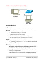
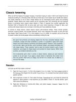
As is shown in Figure 8.1, there are three main processes in block ciphers:
encryption, decryption and key schedule. For the encryption process, the input
is plaintext and the output is ciphertext. For the decryption process, ciphertext
becomes the input and the resultant output is the original plaintext. A number
of rounds are performed for encryption/decryption on a single block. Each
round uses a round key which is derived from the cipher key through a process
called key scheduling. Those three processes are further discussed below.
Plaintext
1 1 1 1 1 1
i
Block Cipher
Encryption
i
1 1 M M
Ciphertext
round
1
roi
^
ind2 I
keyl|key2| |keyn
4
Key Schedule
Round transformation
Ciphertext
1 1 1 1 1 1
1
Block Cipher
Decryption
i
1 1 M 1 1
Plaintext
round n
Fig. 8.1. General Structure of a Block Cipher
Block Cipher Encryption
Many modern block ciphers are Fiestel ciphers
[342].
Fiestel ciphers divide
input block into two halves. Those two halves are processed through n number
of rounds. In the final round, the two output halves are combined to produce
a single ciphertext block. All rounds have similar structure. Each round uses
Please purchase PDF Split-Merge on www.verypdf.com to remove this watermark.
224 8. General Guidelines for Implementing Block Ciphers in FPGAs
a round key, which is derived from the previous round key. The round key for
the first round is derived from the user's master key. In general all the round
keys are different from each other and from the cipher key.
Many modern block ciphers partially or completely employ a similar Fies-
tel structure. DES is considered a perfect Fiestel cipher. Modern block ciphers
also repeat n rounds of the algorithm but they do not necessarily divide the
input block into two halves. All the rounds of the algorithm are generally sim-
ilar if not identical. Round operations normally include some non-linear trans-
formations like substitution and permutation making the algorithm stronger
against crypt analytic attacks.
Block Cipher Decryption
As it was explained, one of the main characteristics of a Fiestel cipher is
the usage of a similar structure for encryption and decryption processes. The
difference lies on the order that the round keys are applied. For decryption,
round keys are used in reverse order as that of encryption. Modern block
ciphers also use round keys following a similar style, however, encryption and
decryption processes for some of them may not be the same. In any case, they
preserve the symmetric nature of the algorithm by guaranteeing that each
transformation will always have its corresponding inverse. As a result both,
the encryption and decryption processes tend to appear similar in structure.
Key Schedule
The round keys are derived from the user key through a process called key
scheduling. Block ciphers define several transformations for deriving the round
keys to be utilized during the encryption and decryption processes. For some
of them, round keys for decryption are derived using reverse transformations.
Alternatively, keys derived for encryption can be simply used during the de-
cryption process in reverse order.
8.2.2 Design Principles for a Block Cipher
During the last two decades both, theoretical new findings as well as innova-
tive and ingenious practical attacks have significantly increase the vulnerabil-
ity of security services. Every day, more effective attacks are launched against
cryptographic algorithms. We also have seen a tremendous boost in computa-
tional power. Successful exhaustive key search engines have been developed in
software as well as in hardware platforms. As a consequence of this, old cryp-
tographic standards were revised and new design principles were suggested to
improve current security features. In this subsection, we analyze some of the
key features that directly impact the design of a block cipher.
Please purchase PDF Split-Merge on www.verypdf.com to remove this watermark.
8.2 Block Ciphers 225
Key Size
If a block cipher is said to be highly resistant against brute force attack, then
its strength is determined by its key length: the longer the key, the longer it
takes before a brute force search can succeed. This is one of the reasons why,
modern block ciphers employ key lengths of 128 bits or more.
Variable Key Length
On the one hand, longer keys provide more security against brute force at-
tacks.
On the other hand, a large key length may slow down data transmission
due to low encryption speed. Modern block ciphers therefore offer variable
key lengths in order to support different security and encryption speed com-
promises. All the five finalists of the 2000 competition for selecting the new
advance encryption standard, namely, RC6, Twofish, Serpent, MARS and Ri-
jndael, provide variable key lengths.
Mixed Operations
In order to make the job of a cryptanalyst more complex, it is considered useful
to apply more than one arithmetic and/or Boolean operators into a block
cipher. This approach adds more non-linearity producing complex functions
as an alternative to S-boxes (substitution boxes). Mixed operations are also
used in the construction of S-boxes to add non-linearity thus making them
produce more unpredictable results.
Variable Number of Rounds
Round functions in crypto algorithms add a great deal of complexity, which
impHes that the crypto-analysis process becomes significantly less amenable.
By increasing the number of rounds larger safety margins are provided. On
the contrary, a large number of rounds slows cipher encryption speed. Mod-
ern block ciphers provide variable number of rounds allowing users to trade
security by time. It should be noticed that the strength of a given crypto
algorithm is also linked with the other design parameters. For example, AES
with 10 rounds provides higher security as compared to DES with 16 rounds.
Variable Block Length
The security of a block cipher against brute force attacks is dependent upon
key and block lengths. Longer keys and block lengths obviously imply a bigger
search space, which tend to give more security to a cipher algorithm. As
it has been said, modern ciphers support variable key and block lengths,
thus assuring that the algorithm becomes more flexible according to different
security requirement scenarios.
Please purchase PDF Split-Merge on www.verypdf.com to remove this watermark.
226 8. General Guidelines for Implementing Block Ciphers in FPGAs
Fast Key Setup
Blowfish uses a lengthy key schedule. Therefore, the process of generating
round keys for encrypting/decrypting a single data block may take a signifi-
cant amount of time. On the other hand, this characteristic also adds security
to Blowfish in the sense that it greatly magnifies the time to search all possibil-
ities for round keys. However for those applications where the cipher key must
be changed frequently, a fast key setup is needed. For example, overheads due
to key setup during the encryption of the security Internet protocol (IPSec)
packets are quite considerable. That is why most modern block ciphers offer
simple and fast key schedule algorithms. Rijndael Key schedule algorithm is
a good example of an efficient process for round key generation.
Software/Hardware Implementations
It was the time when crypto algorithms were designed to get an efficient im-
plementation on
8-bit
processors. Most of their arithmetic/logical functions
were designed to operate on byte level. Perhaps, encryption speed was not a
must have issue as it is now. Those times has gone for good. There are applica-
tions which require high encryption speeds either for software or for hardware
platforms. This is why cryptographers started to include those functions in
crypto algorithms which can be efficiently executed in both software and hard-
ware platforms. For example, the XOR operation can be found in virtually
all modern block ciphers, among other reasons, because of its eflficiency when
implemented in software as well as in hardware platforms.
Simple Arithmetic/Logical Operations
A complex crypto algorithm might not be strong enough cryptographically
The attribute of simplicity can be seen in most of the strong block ciphers used
nowadays. They mainly include easily understandable bit-wise operations.
Table 8.1 describes key features for some famous block ciphers including
the five finalists (AES, MARS, RC6, Serpent, Twofish) of the NIST-organized
contest for selecting the new Advanced Encryption Standard. It can be seen
that modern block ciphers use high block lengths of 128 bits or more. Similarly
they provide high key lengths up till 448 bits. Both block and key lengths in
block ciphers are often variable to trade the security and speed for the chosen
algorithm. Number of rounds ranges from 8 to 32. For some block ciphers the
number of round is fixed but for some others that number can vary depending
on the chosen block and key lengths.
It is noticed that most block ciphers can be eflficiently implemented in
software and hardware platforms. All block ciphers generally include bit-wise
(XOR, AND) and shift or rotate operations. Excluding a small minority of
block ciphers, most algorithms use the so-called S-boxes for substitution. Fast
key set-up is an important feature among modern block ciphers. They are
Please purchase PDF Split-Merge on www.verypdf.com to remove this watermark.
8.2 Block Ciphers 227
Table 8.]
Properties
Block length
Key length
No.
of rounds
Software
Hardware
Symmetric
Bit-operations
Permutation
S-Box
1
Shift/rotate
|Fast key setup
DES
64
64
16
V
%/
V
V
V
V
V
V
. Key Features for Some Famous Block (
Blowfish
64
32-448
16
V
V
V
V
X
V
X
X
IDEA
64
128
8
V
V
V
V
X
X
V
V
AES
128-256
128-256
10-14
V
V
X
v/
X
V
V
V
MARS
128
128-448
32
V
V
X
V
X
V
V
V
RC6
128
128-256
20
V
sj
X
%/
X
X
V
^/
Ciphers
Serpent
128
256
32
x/
x/
X
^
N/
%/
sj
v
TwoFishl
128
128-192
16
^/
V
sj
v/
sj
%/
V
sj
not always symmetric, that is, same building blocks used for encryption not
necessarily can be used for decryption.
8.2.3 Useful Properties for Implementing Block Ciphers in FPGAs
Hardware implementations are intrinsically more physically secure: key ac-
cess and algorithm modification is considerably harder. In this subsection we
identify some useful properties in symmetric ciphers that have the potential
of being nicely mapped to the structure of reconfigurable hardware devices.
Bit-Wise Operations
Most of the block ciphers include bit-level operations like AND, XOR and
OR which can be efficiently implemented and executed in FPGAs. Indeed,
those operations utilize a relatively modest amount of hardware resources.
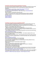
The primitive logic units in most of the FPGAs are based on 4-input/l-ouput
configuration. This useful feature of FPGAs allow to build 2, 3, or 4 input
Boolean function using the same hardware resources as shown in Figure 8.2.
Substitution
Substitution is the most common operation in symmetric block ciphers which
adds maximum non-hnearity to the algorithm. It is usually constructed as a
look-up table referred to as substitution box (S-Box). The strength of DES
heavily depends on the security robustness of its S-boxes. AES
S-box
is used
in both encryption and decryption processes and also in its key schedule al-
gorithm.
Please purchase PDF Split-Merge on www.verypdf.com to remove this watermark.
228 8. General Guidelines for Implementing Block Ciphers in FPGAs
Logic Cell
of
FPGA
4-in/1-out
Fig. 8.2. Same Resources for 2,3,4-in/l-out Boolean Logic in FPGAs
Formally, an
S-box
can be defined as a mapping of n input to m output bits,
i.e., F : ZJ"
—>
^2^. When n = m the mapping is reversible and therefore it is
said to be bijective. AES hsts only one S-Box, which happens to be reversible,
but all eight DES S-boxes are not^
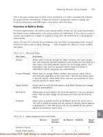
FPGA devices offer various solutions for the implementation of substitu-
tion operation as shown in Figure 8.3.
• The primitive logic unit in FPGAs can be configured into memory mode.
A 4-in/l-out LUT provides 16 x 1 memory. A large number of LUTs can
be combined into a big memory. This might be seen as a fast approach
because the
S-Box
pre-computed values can be stored, thus saving valuable
computational time for
S-Box
manipulation.
• The values for S-boxes in some block ciphers can also be calculated. In
this case, if the target device does not contain enough memory, then one
can use combinational logic to implement S-boxes. That could be rather
slow due to large routing overheads in FPGAs.
• Some FPGA devices contain built-in memory modules. Those are fast
access memories which do not make use of primitive logic units but they
are integrated within FPGAs. The pre-computed values for S-boxes can
be stored in those dedicated modules. That could be faster as compared to
store
S-box
values in primitive logic units configured into memory mode.
As it was described in Chapter 3, many FPGA devices from different
manufacturers contain those memory blocks, frequently called BRAMs.
Permutation
Permutation is a common block cipher primitive. Fortunately, there is no
cost associated with this operation since it does not make use of FPGA logic
^ It is noticed that the number of candidate Boolean functions for building an n
bit input/m bit output
S-box
is given as 2'^^ . It follows that even for moderated
values of n and m, the size of the search space becomes huge. However, not all
Boolean functions are suitable for building robust S-Boxes. Some of the desired
cryptographic properties that good candidate Boolean functions must have are:
High non-linearity, high algebraic degree and low auto-correlation, among others.
Please purchase PDF Split-Merge on www.verypdf.com to remove this watermark.
8.2 Block Ciphers 229
—
LUT
4x1
LUT
4x1
LUT
4x1
-
BRAM
BRAM
BRAM
(a) LCs configured
in memory mode
(b) LCs configured
in logic mode
(c) Using BRAMs
Fig. 8.3. Three Approaches for the Implementation of
S-Box
in FPGAs
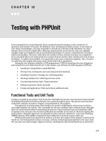
resources. It is just rewiring and the bits are rearranged (concatenated) in
the required order. Figure 8.4 demonstrates a simple example of permuting 6
bits only. That strategy can be extended for the permutation operation over
longer blocks.
Permutation for
6
bits
Fig. 8.4. Permutation Operation in FPGAs
Shift &; Rotate
Shift is simpler than the permutation operation. Shift operation is normally
performed by extracting some particular bit/byte values from a larger register.
One practical example of this situation is: retrieving a
6-bit
sub-vector from a
48-bit state register for their further substitution in DES. This operation can
be implemented using wide data buses, which are then divided into small buses
carrying the required bit/byte values. A typical byte-level shift operation is
shown in Figure 8.5a.
Please purchase PDF Split-Merge on www.verypdf.com to remove this watermark.
230 8. General Guidelines for Implementing Block Ciphers in FPGAs
In some cases, the input data is shifted n bits and n zeroes are added, a
process known as zero padding. In FPGAs, zero padding for n bit? is achieved
by simply connecting n bits to the ground as shown in Figure 8.5b.
Most block ciphers (such as AES, RC6, DEAL, etc.) use the rotation op-
eration. It is similar to shift operation but with no zero padding. Instead, bit
wires are re-grouped according to a defined setup. For example, for a 4-bit
buffer, shifting left aoaia2a3 by 1-bit becomes aia2as0, whereas rotating left
by 1-bit produces aia2a3ao.
Fixed rotation is trivial and there is no cost associated with it. Variable
rotation is also used by some cryptographic algorithms (RC5, RC6, CAST)
however this is not a trivial operation anymore.
IN[31:0]
-A=IN[31:24]
-B = IN[16:8]
-C = IN[23:17]
- D = IN[7:0]
(a) Address required
bits only
7 BITS
-OUT[31:0]
IN[24:0] —
(b) Connect to ground
Fig. 8.5. Shift Operation in FPGAs
Iterative Design Strategy
Block ciphers are naturally iterative, that is, n iterations of the same transfor-
mations, normally called rounds, are made for a single encryption/decryption.
An iterative design strategy is a simple approach which implements the cipher
algorithm by executing n iterations of its rounds. Therefore, n clock cycles are
consumed for encrypting/decrypting a single block, as shown in Figure 8.6.
Obviously, this is an economical approach in terms of required hardware area.
But it slows cipher speed which is n times slower for a single encryption. Such
architectures would be useful for those applications where available hardware
resources are limited and speed is not a critical factor.
Pipeline Design Strategy
In a pipehne design, all the n rounds of the algorithm are unrolled and registers
are provided between two consecutive rounds as shown in Figure 8.7. All the
intermediate registers are triggered at the same clock by shifting data to the
next stage at the rising/falling edge of the clock. Once all the pipeline stages
are filled, the output blocks starts appearing at each successive clock cycle.
Please purchase PDF Split-Merge on www.verypdf.com to remove this watermark.
8.2 Block Ciphers 231
CZFT
^^
-^^
One
Round
^ Select
Latch
* 1
CE CLK
Out
Fig. 8.6. Iterative Design Strategy
This is a fast solution which increases the hardware cost to approximately n
times as compared to an iterative design.
IN-H
Round
H Latch H
CE CLK
Round
H Latch
CE CLK
n
Round
Latch ^•Out
CE CLK
Fig. 8.7. Pipeline Design Strategy
Sub-pipelining Design Strategy
Figure 8.8 represents a sub-pipeline design strategy. As shown in Figure 8.8,
Sub-pipelining is implemented by placing the registers between different stages
of a single round for a pipehne architecture. That improves performance of
the pipeline architecture as those internal registers shift the results within the
round when outputs of a round are being transferred to the next round. It has
been experimentally demonstrated that careful placement of those registers
within a round may produce a significant increase in the design performance.
Round
Round
n
Round
IN-H
Latch
CLK2
Latch HI Latch | L-] Latch
CE CLK1
CE CLK1
I Latch I U
Latch
•Out
CE CLK1
Fig. 8.8. Sub-pipeline Design Strategy
Please purchase PDF Split-Merge on www.verypdf.com to remove this watermark.
232 8. General Guidelines for Implementing Block Ciphers in FPGAs
Managing Block Size
Modern block ciphers operate on data blocks of 128 bits or more. Unlike
software implementations on general-purpose microprocessors, FPGAs allow
parallel execution of the whole data block provided that there is no data de-
pendency in the algorithm. Therefore, it is always useful to dissection the
cipher algorithm looking for possible parallelization versions of it. Furhter-
more, FPGAs offer more than 1000 external pins to be programmable for
inputs or outputs. This is advantageous when the communication is needed
with several peripheral devices on the same board simultaneously.
Key Scheduling
Fast key setup is one of the characteristics in modern block ciphers. The
keys are required to be changed rapidly in some cryptographic applications.
It is possible to reconfigure FPGA device for the key schedule module only
whenever a change in the key is desired
Key Storage
It is recommendable for cryptographic applications to make use of different
secret keys for different sessions. FPGAs provide enough memory resources
to store various session keys. As the keys are stored inside an FPGA, it is
therefore valid to say that FPGA implementations are physical secure^.
8.3 The Data Encryption Standard
On August, 1974, IBM submitted a candidate (under the name LUCIFER)
for cryptographic algorithm in response to the 2nd call from National Bureau
of Standards (NBS), now the National Institute of Standards k, Technology
(NIST)[253],
to protect data during transmission and storage.
NBS launched an evaluation process with the help of National Security
Agency (NSA) and finally adopted on July 15, 1977, a modification of LU-
CIFER algorithm as the new Data Encryption Standard (DES). The Data
Encryption Standard
[392],
known as Data Encryption Algorithm (DEA) by
the ANSI [392] and the DEA-1 by the ISO [152] remained a worldwide stan-
dard for a long time until it was replaced by the new Advanced Encryption
Standard (AES) on October 2000.
DES and TripleDES provide a basis for comparison of new algorithms. DES
is still used in IPSec protocols, ATM encryption, and the secure socket layer
(SSL) protocol. It is expected that DES will remain in the pubhc domain
^ See §3.7 for more details on the security offered by contemporary reconfigurable
hardware devices.
Please purchase PDF Split-Merge on www.verypdf.com to remove this watermark.
8.3 The Data Encryption Standard 233
for a number of years. DES expired as a federal standard in 1998 and it
can only be used in legacy systems. Nevertheless, DES continues to be the
most widely deployed symmetric-key algorithm. Its variant, Triple-DES, which
consists on applying three consecutive DES without initial (direct and inverse)
permutations between the second and the third DES, coexists as a federal
standard along with AES.
A detail description of the DES algorithm can be seen in [317, 228, 362].
The description of DES in this chapter it closely follows that of
[317].
Description
DES uses a 64-bit long key. The eight bits of that key are used for odd parity
and therefore they are not counted in the key length. The effective key length
is therefore 56 bits, providing 2^^ possible keys. DES is a block cipher: It
encrypts/decrypts data in 64-bit blocks using a 56-bit key. DES is a symmet-
ric algorithm: the same algorithm and the key are used for both encryption
and decryption. DES is an iterative cipher: the basic building block (a sub-
stitution followed by a permutation) called a round is repeated 16 times. For
each DES round, a sub-key is derived from the original key through the pro-
cess of key scheduling. Although the key scheduling algorithm for encryption
and decryption is exactly the same, produced round keys for decryption are
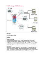
used in reverse order. Figure 8.9 shows the basic algorithm flow for both the
encryption and key schedule processes.
Encryption begins with an initial permutation (IP), which scrambles the
64-bit plain-text in a fixed pattern. The result of the initial permutation is
sent to two 32-bit registers, called the right half register, RQ and left half
register, LQ. Those registers hold the two halves of the intermediate results
through successive 16 applications of the function fk which is given by (n =
0 to 15):
Lfi = Hn-i (R ^\
After 16 iterations, the contents of the right and left half registers are
passed through the final permutation IP~\ which is the inverse of the initial
permutation. The output of IP~^ is the 64-bit ciphertext.
A detailed explanation of those three operations is provided in the rest of
this Subsection. The key sechedule algorithm of DES is explained at the end.
3.3.1 The Initial Permutation (IP~^)
The initial permutation is the first operation applied to the input 64-bit block
before the main iterations of the algorithm start. It transposes the input block
as described in Table 8.2. For example, the initial permutation moves bit 58
to bit position 1, bit 50 to bit position 2, bit 42 to bit position 3, and so forth.
Please purchase PDF Split-Merge on www.verypdf.com to remove this watermark.
234 8. General Guidelines for Implementing Block Ciphers in FPGAs
56-bit Key
1 Plaintext |
t 1
(
; ) C-
<hr<if*z:^
^rKi?^
1 1
^>K!?*
C^
Ciphertext
'ZD
t
f{Ru
K2?)
1
/?14,
Kisy
b
I PC
Ki^
PC-2
'cTi fpn
'"Rotated /^ Rotate "\
Left y V Left 7
^RotateA ARotateA
Left J ^ Left J
C2
I I D2
K2M-\
PC-2
I I ~T
'RotateN /'Rotate^
Left y V Left
I C16 I I D16
K.6^
PC-2 ] I —J
Fig. 8.9, DES Algorithm
The initial permutation has no cryptographic relevance on DES security.
Its primary purpose is to make it easier for an application to load plain-text
into a DES chip in byte-sized pieces. Initial permutation implementation in
hardware is trivial but cumbersome in software.
8.3.2 Structure of the Function /^
The 64-bit output from the initial permutation is divided into two halves LQ
and RQ of 32 bits each as shown in Figure 8.9. Both halves go through the 16
iterations of the function fk (Eq. 8.1) which is described below.
For the first iteration, RQ and 48-bit round key are the two inputs. We
first expand RQ from 32 bits to 48 bits by using the expansion permutation
(Permutation E).
Please purchase PDF Split-Merge on www.verypdf.com to remove this watermark.
8.3 The Data Encryption Standard 235
Table 8.2. Initial Permutation for 64-bit Input Block
58 50 42 34 26 18 10 2
60 52 44 36 28 20 12 4
62 54 46 38 30 22 14 6
64 56 48 40 32 24 16 8
57 49 41 33 25 17 9 1
59 51 43 35 27 19 11 3
61 53 45 37 29 21 13 5
63 55 47 39 31 23 15 7
The Expansion Permutation (Permutation E)
This operation expands 32-bit right half Ri to 48 bits. Some bits are therefore
repeated and the order of the bits is also changed as shown in Table 8.3.
32
8
16
24
Table 8.3. E-bit Selection
12 3 4
9 10 11 12
17 18 19 20
25 26 27 28
5 4
13 12
21 20
29 28
5 6 7 8
13 14 15 16
21 22 23 24
29 30 31 32
9
17
25
1
Table 8.3 shows the position of input bits after applying the permutation
E. For example, the bit in position 3 of input block moves to position 4, bit
21 moves to position 30 and 32 of the output block. The redundant bits and
their positions in the output block can be easily seen as they are outside the
squares in boldface letter as shown in Table 8.3.
This operation has two purposes. First, it makes the size of right half
register equal to the size of the key to perform XOR operation. Second, the
48-bit expanded register can be compressed during the substitution operation.
The output 48-bit is XORed with the 48-bit round key which is then
divided into
6-bit
long eight groups. The eight groups each of six bits are
replaced to eight groups of four bits each by applying the substitution boxes
(S-Boxes) whose values are provided by the algorithm.
The S-Box Substitution
DES
S-box
is a 64-entry table arranged into four rows and sixteen columns.
The input is a
6-bit
address and the output is 4-bit long. The first and last
bits aoas of
6-bit
address aoaia2a3a4a5 represent the row number while the
middle four bits aia2a3a4 denote the column number. Thus the
S-box
will
substitute 101011 with the entry at row 4th (11) and column 6th (0101). To
Please purchase PDF Split-Merge on www.verypdf.com to remove this watermark.
236 8. General Guidelines for Implementing Block Ciphers in FPGAs
Row]
0
1
1
2
3 1
0
1
2
3
ro~]
1
2
3
0
1
2
3
ro~i
1
2
1 3
ro~"
1
2
1 3
1
0
1
2
1
3
ro~
1
2
1
^
Table 8.4.
DBS S-boxes
Column 1
"oi
U
0
4
15
15
3
0
13
10
13
13
1
Vf
13
10
3
ry
14
4
11
|l2
10
9
|4
T^
13
1
1
6
TT3
1
7
1
2
1|2
4
15
1
12
1
13
14
8
0
7
6
10
13
8
6
15
12
11
2
8
1
15
14
3
11
0
4
11
2
15
11
1
13
7
14
8
8
4
7
10
9
0
4
13
14
11
9
0
4
2
1
12
Tol
4
15
2
2
11
11
13
8
13
4
14
3|4
1
4
8
2
14
7
11
1
14
9
9
0
3
5
0
6
1
12
11
7
15
2
5
12
14
7
13
8
rr
[8
1
7
2
14
13
4
6
15
10
3
6
3
8
6
0
6
12
10
7
4
10
1
9
7
2
9
15
4
12
1
6
10
9
4
5 |6
T5I
2
6
9
11
2
4
15
3
4
15
9
6
15
11
1
10
7
13
14
2
12
8
5
0
9
3
4
15
3
12
10
IT
13
2
1
3
8
13
4
15
6
3
8
9
0
7
13
11
13
7
2
6
9
12
15
8
1
7
10
11
7
14
8
7
8
1
11
7
4
14
1
2
5
10
0
7
10
3
13
8
6
1
8
13
8
5
3
10
13
10
14
7
1
4
2
13
8
3
10
15
5
9
12
5
11
1
2
11
4
1
4
15
9
8
5
15
6
T
6
7
11
3
14
10
9
10
12
0
15
9
10
6
12
11
7
0
8
6
13
8
1
15
2
7
1
4
5
0
9
15
l3^
1
0
14
12
3
15
5
9
5
6
12
10|11|12|13|14|15|
6
12
9
3
2
1
12
7
12
5
2
14
8
2
3
5
3
15
12
0
3
13
4
1
9
5
6
0
13
6
10
9
12
11
7
14
13
10
6
12
7
14
12
3
5
12
14
11
15
10
5
9
T
14
10
7
7
12
8
15
14
11
13
0
5
9
3
10
12
6
9
0
11
12
5
11
11
1
5
12
13
3
6
10
IT
0
1
6
5
2
0
14
5
0
15
3
9I
5
10
0
0
9
3
5
4
11
10
5
12
10
2
7
0
9
3
4
Tl
11
13
0
10
15
5
2
0
14
3
5
"0"^
3
5
6
5
11
2
14
2
15
14
2
4
14
8
2
14
8
0
5
"51
3
11
8
6
8
9
3
12
9
5
16
8
0
ill
lol
5
15
l\
~8l
1
7
I2J
15
9
4
}A
T\
6
14
3
11
8
6
13
1
6
2
12
7
2
8
11
S-Box|
Si
S2
S3
S4
S5
Se
S7
Ss
substitute a 48-bit word, DES uses eight S-boxes each of size 64 x 4 = 256
bits occupying a total of 2 Kbits memory as shown in Table 8.4
The 32-bit
S-Box
output undergoes through another permutation, which
is called P-Box Permutation.
The P-Box Permutation
In this step, the input 32-bit (output of the
S-box)
is permuted to get the
32-bit output. The bit position for P-Box permutation is shown in Table 8.5.
Please purchase PDF Split-Merge on www.verypdf.com to remove this watermark.
8.3 The Data Encryption Standard 237
As shown in Table 8.5, bit 21 moves to bit 4, bit 4 moves to bit 31 and so on.
There is no repetition in bits and none of them is ignored.
Table 8.5. Permutation P
16 7 20 21 29 12 28 17 1 15 23 26 5 18 31 10
2 8 24 14 32 27 3 9 19 13 30 6 22 11 4 25
The 32-bit output after P-Box permutation is XORed with
LQ.
In the next
iteration, we will have L2 = Ri^ which is the block we just calculated and then
we must calculate i^2, repeating the same procedure as it was used for Ri. At
the end of the 16*^ iteration we have the blocks Lie and RIQ. The order of
these blocks is reversed and two blocks are concatenated into a 64-bit block
RIQLIQ,
The final permutation IP~^ is then applied.
The Final Permutation IP'^
Table 8.6 provides the bit positions for the final permutation which oper-
ates on 64-bit input block producing 64-bit output block. This completes the
encryption process for a single block.
Table 8.6. Inverse Permutation
40
8
48 16 56 24 64 32
39
7
47 15 55 23 63 31
38 6 46
14
54 22 62 30
37
5
45 13 53 21 61 29
36 4 44
12
52 20 60 28
35 3 43 11 51 19 59 27
34
2
42
10
50 18 58 26
33
1
41 9 49
17
57 25
Decryption is simply the inverse of encryption which is carried out by
repeating the same steps as they were explained above. Only the round keys
are applied in the reverse order.
8.3.3 Key Schedule
The round keys for all the 16 rounds are derived from the original key as shown
in Figure 8.9. First the 64-bit DES key is reduced to 56 bits by ignoring every
S^^ bit governed by the Table 8.7. This is referred to as Permuted Choice One
(PC-1).
The 48-bit round keys are then derived as follows.
Please purchase PDF Split-Merge on www.verypdf.com to remove this watermark.
238
General Guidelines for Implementing Block Ciphers in FPGAs
Table 8.7. Permuted Choice one PC-1
57
49 41 33 25 17 9
10
1 58 50 42 34 26 18
2 59
51
43 35 27 19 11
63 55 47 39 31 23 15
14
3 60 52 44 36
7 62 54 46 38 30 22
6 61 53 45 37 29
21
13
5 28 20 12 4
The 56-bit output after PC-1 is divided into two halves Co and DQ. In
each round, the two halves undergo a circular left shift or rotation by either
one or two bits, depending on the round as shown in Table 8.8.
Table 8.8. Number of Key Bits Shifted per Round
Round No. 1 2 3 4 5 6 7 8 9 10 11 12 13 14 15 16
Bits shifted
1122222212 2 2 2 2 2 1
After the shift operation, the two halves are concatenated and serve as
input to Permuted Choice Two (PC-2) as given in Table 8.9. The resulting
48-bit block is the required round key. Both halves before permutation PC-2
are also used as the two inputs to generate round keys for the next round as
is shown in Figure 8.9.
Table 8.9. Permuted Choice two (PC-2)
14 17 11 24
23 19 12 4
1 5 3 28 15 6 21 10
26 8 16 7 27 20 13 2
41 52
31
37 47 55 30 40 51 45 33 48
44 49 39 56 34 53 46 42 50 36 29 32
8.4 FPGA Implementation of DES Algorithm
In this section DES implementation is described on reconfigurable hardware
platform. The design steps for the development of FPGA architecture are
explained along with some useful design techniques for the improvement of
design performance. Performance results and comparison with the previous
FPGA implementations of DES are presented at the end of this Section.
8.4.1 DES Implementation on FPGAs
Figure 8.10 is a block diagram representation of DES implementation in FP-
GAs.
As it has been mentioned before, permutation operations do not occupy
Please purchase PDF Split-Merge on www.verypdf.com to remove this watermark.
8.4 FPGA Implementation of DES Algorithm 239
logical resources of the device and it can be implemented by rearranging bit
positions for the outgoing bu^ (change of wires), hence it is free of cost. DES
includes several permutations (initial, final, permutation E, permutation P).
The building blocks for those operations in Figure 8.10 are therefore symbolic
representations having no logic inside.
Each DES
S-Box
occupies 64 x 4—256-bit memory. Hence, a total of 2K
(2048 bits) memory is required for the construction of eight S-Boxes. If it
is not intended to use dedicated memory resources, only 32 CLB slices are
needed for an
S-Box
on XiHnx VirtexE devices. Some other fabric resources of
the device were occupied for the implementation of latches (Slice Flip Flops)
and logic blocks for XOR operation.
64
RIN
32
V
LIN
32
REG
A
32
REG
B
permutation E
sub-key
LEFT
RIGHT
ho
IP-'
64
_J I 32 r^
permutation P
N
^48
OUT
S1
S2
S3
S4
S5
S6
S7
S8
S-Boxes
- 32
Fig. 8.10. DES Implementation on FPGA
DES chip consists of four I/O pins: three inputs and one output. The
three input pins are Chip Enable (CE), Clock (CLK), and input data (IN).
The single output pin is named as OUT. The CE signal activates the DES
chip,
whereas the CLK is the only master clock in charge of driving the whole
circuitry. It is used to generate all control signals needed for the synchroniza-
tion of the data flow.
When the CE signal is in low, it enables the circuit. As a consequence,
the input 64-bit block after passing through initial permutation (bit wires
rearranged) is partitioned into two halves RIN and LIN. At the first rising
edge of CLK, both RIN and LIN are transferred to the output of the two
registers REGA and REGB. The REGA output (RIN) goes through a number
of operations: Permutation E, addition with sub-key, substitution (through
S-Boxes), Permutation P, and then finally addition with the initial REGB
output (LIN). On the next clock, the old right half (RIGHT) is the input of
register REGB and the new left half (LEFT) is the input of register REGA.
In the 16*^ clock cycle the two RIGHT and LEFT halves are concatenated
(two buses joined together) and they are pass through the inverse permutation
(IP-^) producing a vahd 64-bit DES ciphertext at OUT pin.
Please purchase PDF Split-Merge on www.verypdf.com to remove this watermark.
240 8. General Guidelines for Implementing Block Ciphers in FPGAs
It is to be noted that the parallel structure for the eight DES S-Boxes
contributes with a significant reduction of the critical path for encryp-
tion/decryption.
8.4.2 Design Testing and Verification
DES implementation wats made on XCV400e-8-bg560 VirtexE device using
Xilinx Foundation Series F4.1i. The design tool provides two options for de-
sign testing and verification: functional simulation and timing verification.
Functional verification tests the logical correctness of the design. It is per-
formed after the design entry has been completed using VHDL or using library
components of the target devices. It detects logical errors without considering
circuit overheads Uke path delays, synchronization, etc. A netlist of the logic
components in the design is created by the design tool, which is then mapped
to the available resources of the actual target device. Timing verifications are
made at this stage.
Both functional and timing verifications must be performed for a success-
ful design implementation. For both cases, test vectors are used for result
verification and testing. Table 8.10 shows a simple test vector used to verify
DES chip.
Table 8.10.
Test Vectors
Input Block
1
First Permutation |/(R,K) [Second permutation
LIN=OxFFFFOOOO
RIN=OxAAAAAAAA
LFOUT=0x 06060606
RFOUT=0
X
E7E7E7E7
LEFT=0x49DE9DF2
RIGHT=0
X
C7EEC966
LOUT=0xl7F77A33
ROUT=0x7B7AB72A
Figure 8.11 and Figure 8.12 show the results for the functional simulation
and the timing verification for DES implementation in FPGA. Notice that
the diff"erence between Figure 8.11 and 8.12. Time delays in Figure 8.12 are
clearer.
8.4.3 Performance Results
FPGA implementation of DES algorithm was accomplished on a VirtexE de-
vice XCV400e-8-bg560 using Xifinx Foundation Series F4.1i as synthesis tool.
The design was coded using VHDL language. It occupied 165 (3%) CLB slices,
117 (1%) shce Flip Flops and 129 (41%) I/Os. The design achieves a frequency
of 68.05 MHz (14.7 rjS). It takes 16 clock cycles to encrypt one data block
(64-bits). Therefore, the achieved throughput is (68.05 x 64)/16=274 Mbits/s.
8.5 Other DES Designs
Several FPGA implementations of DES have been reported in the literature
achieving throughput ranges from 26 Mbps to 21.3 Gbps. In Table 8.11 we
Please purchase PDF Split-Merge on www.verypdf.com to remove this watermark.
8.5 Other DES Designs 241
<SS3ZH!ISSSBSSSiSISS!3E9i
^
Fie
Signal Waveform OftviCQ Optbitt Toott View Window
He^
ai£fl&I3®l[!i!^ZZ3SMI
Bn:iK.<bw)/32
\ipM
ICE
ib-lK
ip.2K
ICLSK
\lfL*K
BRESET
bsEL.
.(hex)«4
pbuB_K£H
BWAB_SEC
bpOUTChex)*;
bpOUT (hex)/:
pb;iGHT.(bex)/;
btoUT.(hex)#3;
sboUT (hex>#3i
I
3r~l^-v-)(2viJgII]EI-DEa&L^y- 'i^'^'lSrwr^'WJIimiBS J^^
Fig. 8.11. Functional Simulation
m
fm^mm^Mmmivii\f!9mmminfm/!m'imm
^ Ht
Stgrwl Wavrform Device Opttoni Toob Vtow VWrxtow
He^
Q.O
ni^—Ji-<1 c-> j
Oh*
BOOris NOOhi ISOCTi* tSfJOn* POOiij KJO&n* pOOr^s
,.!.uJuMtMML.MlnMlMuLn.n.„lH.J.M,InnLMln ' '
[BpB_SEC
bbFOUT.(hox)jr:
bJLOUT
(hex}«3:
BROUT. (hox>*3:
bpLEFT (hex}«3:
Fig. 8.12. Timing Verification
review the fastest designs reported in the literature. They are sorted in de-
scending order. The design reported in [299] by Rouvrou et al achieves a
throughput of 21.3 Gbps and it is the fastest design reported up to this book
publication's date. It consist on a pipeline architecture with a pipeline depth
of 37 stages. The 37 stages for that design were developed by introducing a
dif-
ferent formulation of DES in which a new mathematical expression especially
tailored for FPGA devices is proposed. In the same paper, authors proposed
a different grouping of the stages resulting in a pipeline architecture of 21
stages. The throughput for the second architecture is reported as 14.5 Gbps.
Please purchase PDF Split-Merge on www.verypdf.com to remove this watermark.
242 8. General Guidelines for Implementing Block Ciphers in FPGAs
Author
Rouvroy
et al.[301]
Xilinx [148]
Rouvroy
et al.[301]
Trimberger
et al.[363]
Patterson
et al.[2711
Swankoski
et al.[353l
Trimberger
et al.[363]
McLoone
et al.[225]
FreelP-
Proy [99]
Table 8.11. DBS Comparison: Fastest Designs
Device
XC2V1000-6
XC2V1000-6
XCV300 E8
XCV150-6
Virtex-II
Pro
XCV300 E8
XCVIOOO
XCV400-6
XCV400-6
Design
Strategy
Pipeline
37 cycles
Pip.
48 stages
Pipeline
21 cycles
Pip.
48 stages
(3DES)
Jbits and RTR
17 parallel
DBS blocks
Pip.
16 stages
Pipeline
16 stages
Pipeline
16 stages
Area
Slices
2965
3900
3775 LUT
2904 FF
4216 LUT
5573 FF
1584
5544
4216 LUT
1943 FF
6446
2528
Freq.
(Mhz)
333
237
227
188.7
168
140.6
132
59.5
47.7
Throughput
(Mbps)
21300
15100
14500
12000
10752
9000
8400
3808
3100
T/A
7.18
3.87
N.D.
N.D.
6.75
1.65
N.D.
0.59
1.22
The first architecture is also the most efficient architecture with a throughput
over area ratio of 7.18.
Trimberger et al [363, 148] presented three of the fastest DES designs ever
reported. They are pipelined designs with 48 and 16 stages. A Java-based
(Jbits) DES implementation in [271] achieves the encryption rate of 10752
Mbps.
It implements all DES primitives in FPGA while the key schedule
is processed in software. The communication between the two operations is
made through a Java-based Apphcation Programming Interface (API) which
is intended for runtime creation and modification of the bit-stream.
Initial high-performance designs were reported by McLoone et al [225] and
the free IP project [99]. Both are 16-stage pipeline architectures that report
throughputs around 3 Gbps. The architecture reported by Swankoski et al in
[353] consists of several independent DES blocks (17).
In Table 8.12 we review the most compact designs reported in the fiter-
ature. They are sorted in ascending order. In general, a throughput greater
than 1 Gbps is well beyond reach of compact designs which, otherwise, is
not the main goal of such designs. On the contrary hardware area is the ma-
jor concern for such type of architectures. Most of them implement one DES
round and iteratively process a block to perform encryption/decryption.
Most recent reported designs
[309],
[300] and [353] implement both, ci-
phering and key scheduling. The most compact design was reported by Nazar
et al [309] with a design that occupies just 167 slices. The next one, reported
by Rouvroy et al
[300],
occupies 189 CLB slices attaining better performance
results. Some other designs implement more than one round in order to in-
crease performance
[167].
FPGA implementation of DES in [167] implement
Please purchase PDF Split-Merge on www.verypdf.com to remove this watermark.
8.5 Other DES Designs 243
Table 8.12. DES Comparison: Compact Designs
Author
Nazar et al.[309]
Rouvroy
et al.[300]
CAST [147]
Kapset al.[167|
Swankoski
et al.[353l
Wonget al.[384J
Kaps et al.[167]
Leonard
et al.[204]
Kapset al.[167J
Device
XCV400E
XC2V1000-5
Virtex-II 5
XCV4013 E3
Virtex-Il
Pro
XCV4020E
XCV4013 EX3
XCV4025-4
XCV4013 EX3
Design
Strategy
one round
one round
one round
one round
one round
one round
2 stage pipe
key spec.
4 stage pipe
Area
Slices
167
189
238
262
343
438
433
640
741
Freq.
(Mhz)
68.5
274
N.A.
23.9
203.3
10
23.0
6.0
25.2
Throughput
(Mbps)
274
974
816
91.2
765.7
26.7
183.8
24
402.7
T/A
1.64
5.15
3.43
0.35
2.23
0.06
0.42
0.04
0.54
both
2-stage
and
4-stage
pipeHne approaches obtaining throughput of 183.8
Mbps and 402.7 Mbps, respectively. The design in [384] is a one round DES
implementation on a single-chip FPGA. A fair comparison is not possible with
this design and the one reported in
[204],
because they did not consider key
scheduling.
In Table 8.13 we select those designs presented in Tables 8.11 and 8.12
showing a throughput over area ratio greater than one. In this sense, the
most efficient designs are also high-performance designs.
Author
Houvroy
et al.[301]
Patterson
et al.[2711
Rouvroy
et al.[300l
Xilinx [148]
CAST 1147]
Swankoski
et al.[353l
SwauKOski
et al.[353]
Nazar
et al.[309]
FreeiP-
Proy [99]
Table 8.13
Device
XC2V1000-6
XCV150-6
XC2V1000-5
Virtex-II 5
Virtex-11
Pro
Virtex-11
Pro
XCV400E
XCV400-6
. DES Comparison: Efficient Designs
Design
Strategy
Pip.
37 cycles
J bits and HTH
one round
Pip.
48 stages
one round
one round
17 parallel
DES blocks
one round
Pip.
16 stages
Area
Slices
"2965"
1584
189
3900
238
343
5544
167
2528
Freq.
(Mhz)
"333'"'
168
274
237
N.A.
203.3
140.6
68.5
47.7
Throughput
(Mbps)
21300"
10752
974
15100
816
765.7
9000
274
3100
T/A
^TIB"
6.75
5.15
3.87
3.43
2.23
1.65
1.64
1.22
Finaly, in Table 8.14 we show some other designs for TripleDES. They
are sorted in descending order with respect to performance. Pipeline strategy
Please purchase PDF Split-Merge on www.verypdf.com to remove this watermark.