Tài liệu shi20396 chương 5 ppt
Bạn đang xem bản rút gọn của tài liệu. Xem và tải ngay bản đầy đủ của tài liệu tại đây (370.69 KB, 43 trang )
Chapter 5
5-1
(a)
k =
F
y
; y =
F
k
1
+
F
k
2
+
F
k
3
so
k =
1
(1/k
1
) + (1/k
2
) + (1/k
3
)
Ans.
(b)
F = k
1
y + k
2
y + k
3
y
k = F/y = k
1
+ k
2
+ k
3
Ans.
(c)
1
k
=
1
k
1
+
1
k
2
+ k
3
k =
1
k
1
+
1
k
2
+ k
3
−1
5-2 For a torsion bar,
k
T
= T/θ = Fl/θ,
and so
θ = Fl/k
T
.
For a cantilever,
k
C
= F/δ,
δ = F/k
C
.
For the assembly,
k = F/y, y = F/k = lθ +δ
So
y =
F
k
=
Fl
2
k
T
+
F
k
C
Or
k =
1
(l
2
/k
T
) + (1/k
C
)
Ans.
5-3 For a torsion bar,
k = T/θ = GJ /l
where
J = πd
4
/32
. So
k = πd
4
G/(32l) = Kd
4
/l
. The
springs, 1 and 2, are in parallel so
k = k
1
+ k
2
= K
d
4
l
1
+ K
d
4
l
2
= Kd
4
1
x
+
1
l − x
And
θ =
T
k
=
T
Kd
4
1
x
+
1
l − x
Then
T = kθ =
Kd
4
x
θ +
Kd
4
θ
l − x
k
2
k
1
k
3
F
k
2
k
1
k
3
y
F
k
1
k
2
k
3
y
shi20396_ch05.qxd 8/18/03 10:59 AM Page 106
Chapter 5 107
Thus
T
1
=
Kd
4
x
θ; T
2
=
Kd
4
θ
l − x
If
x = l/2
, then
T
1
= T
2
.
If
x < l/2
, then
T
1
> T
2
Using
τ = 16T /πd
3
and
θ = 32Tl/(Gπd
4
)
gives
T =
πd
3
τ
16
and so
θ
all
=
32l
Gπd
4
·
πd
3
τ
16
=
2lτ
all
Gd
Thus, if
x < l/2
, the allowable twist is
θ
all
=
2xτ
all
Gd
Ans.
Since
k = Kd
4
1
x
+
1
l − x
=
π Gd
4
32
1
x
+
1
l − x
Ans.
Then the maximum torque is found to be
T
max
=
πd
3
xτ
all
16
1
x
+
1
l − x
Ans.
5-4 Both legs have the same twist angle. From Prob. 5-3, for equal shear, d is linear in x. Thus,
d
1
= 0.2d
2
Ans.
k =
π G
32
(0.2d
2
)
4
0.2l
+
d
4
2
0.8l
=
π G
32l
1.258d
4
2
Ans.
θ
all
=
2(0.8l)τ
all
Gd
2
Ans.
T
max
= kθ
all
= 0.198d
3
2
τ
all
Ans.
5-5
A = πr
2
= π(r
1
+ x tan α)
2
dδ =
Fdx
AE
=
Fdx
Eπ(r
1
+ x tan α)
2
δ =
F
π E
l
0
dx
(r
1
+ x tan α)
2
=
F
π E
−
1
tan α(r
1
+ x tan α)
l
0
=
F
π E
1
r
1
(r
1
+l tan α)
l
x
␣
dx
F
F
r
1
shi20396_ch05.qxd 8/18/03 10:59 AM Page 107
108 Solutions Manual • Instructor’s Solution Manual to Accompany Mechanical Engineering Design
Then
k =
F
δ
=
π Er
1
(r
1
+l tan α)
l
=
EA
1
l
1 +
2l
d
1
tan α
Ans.
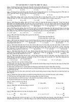
5-6
F = (T + dT) + w dx − T = 0
dT
dx
=−w
Solution is
T =−wx + c
T |
x=0
= P +wl = c
T =−wx + P + wl
T = P +w(l − x)
The infinitesmal stretch of the free body of original length
dx
is
dδ =
Tdx
AE
=
P +w(l − x)
AE
dx
Integrating,
δ =
l
0
[P +w(l − x)] dx
AE
δ =
Pl
AE
+
wl
2
2AE
Ans.
5-7
M = wlx −
wl
2
2
−
wx
2
2
EI
dy
dx
=
wlx
2
2
−
wl
2
2
x −
wx
3
6
+ C
1
,
dy
dx
= 0
at
x = 0
, І
C
1
= 0
EIy =
wlx
3
6
−
wl
2
x
2
4
−
wx
4
24
+ C
2
,
y = 0
at
x = 0
, І
C
2
= 0
y =
wx
2
24EI
(4lx − 6l
2
− x
2
)
Ans.
l
x
dx
P
Enlarged free
body of length dx
w is cable’s weight
per foot
T ϩ dT
w dx
T
shi20396_ch05.qxd 8/18/03 10:59 AM Page 108
Chapter 5 109
5-8
M = M
1
= M
B
EI
dy
dx
= M
B
x +C
1
,
dy
dx
= 0
at
x = 0
, І
C
1
= 0
EIy =
M
B
x
2
2
+ C
2
,
y = 0
at
x = 0
, І
C
2
= 0
y =
M
B
x
2
2EI
Ans.
5-9
ds =
dx
2
+ dy
2
= dx
1 +
dy
dx
2
Expand right-hand term by Binomial theorem
1 +
dy
dx
2
1/2
= 1 +
1
2
dy
dx
2
+ ···
Since
dy/dx
is small compared to 1, use only the first two terms,
dλ = ds −dx
= dx
1 +
1
2
dy
dx
2
− dx
=
1
2
dy
dx
2
dx
І
λ =
1
2
l
0
dy
dx
2
dx
Ans.
This contraction becomes important in a nonlinear, non-breaking extension spring.
5-10
y =−
4ax
l
2
(l − x) =−
4ax
l
−
4a
l
2
x
2
dy
dx
=−
4a
l
−
8ax
l
2
dy
dx
2
=
16a
2
l
2
−
64a
2
x
l
3
+
64a
2
x
2
l
4
λ =
1
2
l
0
dy
dx
2
dx =
8
3
a
2
l
Ans.
y
ds
dy
dx
shi20396_ch05.qxd 8/18/03 10:59 AM Page 109
110 Solutions Manual • Instructor’s Solution Manual to Accompany Mechanical Engineering Design
5-11
y = a sin
π x
l
dy
dx
=
aπ
l
cos
π x
l
dy
dx
2
=
a
2
π
2
l
2
cos
2
π x
l
λ =
1
2
l
0
dy
dx
2
dx
λ =
π
2
4
a
2
l
= 2.467
a
2
l
Ans.
Compare result with that of Prob. 5-10. See Charles R. Mischke, Elements of Mechanical
Analysis, Addison-Wesley, Reading, Mass., 1963, pp. 244–249, for application to a nonlinear
extension spring.
5-12
I = 2(5.56) = 11.12 in
4
y
max
= y
1
+ y
2
=−
wl
4
8EI
+
Fa
2
6EI
(a − 3l)
Here
w = 50/12 = 4.167
lbf/in, and
a = 7(12) = 84
in, and
l = 10(12) = 120
in.
y
1
=−
4.167(120)
4
8(30)(10
6
)(11.12)
=−0.324 in
y
2
=−
600(84)
2
[3(120) − 84]
6(30)(10
6
)(11.12)
=−0.584 in
So
y
max
=−0.324 −0.584 =−0.908
in Ans.
M
0
=−Fa − (wl
2
/2)
=−600(84) − [4.167(120)
2
/2]
=−80 400 lbf ·in
c = 4 − 1.18 = 2.82 in
σ
max
=
−My
I
=−
(−80 400)(−2.82)
11.12
(10
−3
)
=−20.4 kpsi Ans.
σ
max
is at the bottom of the section.
shi20396_ch05.qxd 8/18/03 10:59 AM Page 110
Chapter 5 111
5-13
R
O
=
7
10
(800) +
5
10
(600) = 860 lbf
R
C
=
3
10
(800) +
5
10
(600) = 540 lbf
M
1
= 860(3)(12) = 30.96(10
3
) lbf · in
M
2
= 30.96(10
3
) + 60(2)(12)
= 32.40(10
3
) lbf · in
σ
max
=
M
max
Z
⇒ 6 =
32.40
Z
Z = 5.4in
3
y|
x=5ft
=
F
1
a[l − (l/2)]
6EIl
l
2
2
+ a
2
− 2l
l
2
−
F
2
l
3
48EI
−
1
16
=
800(36)(60)
6(30)(10
6
)I (120)
[60
2
+ 36
2
− 120
2
] −
600(120
3
)
48(30)(10
6
)I
I = 23.69 in
4
⇒ I /2 = 11.84 in
4
Select two
6 in-8.2 lbf/ft
channels; from Table A-7,
I = 2(13.1) = 26.2in
4
,
Z =2(4.38) in
3
y
max
=
23.69
26.2
−
1
16
=−0.0565 in
σ
max
=
32.40
2(4.38)
= 3.70 kpsi
5-14
I =
π
64
(1.5
4
) = 0.2485 in
4
Superpose beams A-9-6 and A-9-7,
y
A
=
300(24)(16)
6(30)(10
6
)(0.2485)(40)
(16
2
+ 24
2
− 40
2
)
+
12(16)
24(30)(10
6
)(0.2485)
[2(40)(16
2
) − 16
3
− 40
3
]
y
A
=−0.1006 in Ans.
y|
x=20
=
300(16)(20)
6(30)(10
6
)(0.2485)(40)
[20
2
+ 16
2
− 2(40)(20)]
−
5(12)(40
4
)
384(30)(10
6
)(0.2485)
=−0.1043 in Ans.
% difference =
0.1043 −0.1006
0.1006
(100) = 3.79% Ans.
R
C
M
1
M
2
R
O
A
O
B
C
V (lbf)
M
(lbf
•in)
800 lbf 600 lbf
3 ft
860
60
O
Ϫ540
2 ft 5 ft
shi20396_ch05.qxd 8/18/03 10:59 AM Page 111
112 Solutions Manual • Instructor’s Solution Manual to Accompany Mechanical Engineering Design
5-15
I =
1
12
3
8
(1.5
3
) = 0.105 47 in
4
From Table A-9-10
y
C
=−
Fa
2
3EI
(l +a)
dy
AB
dx
=
Fa
6EIl
(l
2
− 3x
2
)
Thus,
θ
A
=
Fal
2
6EIl
=
Fal
6EI
y
D
=−θ
A
a =−
Fa
2
l
6EI
With both loads,
y
D
=−
Fa
2
l
6EI
−
Fa
2
3EI
(l +a)
=−
Fa
2
6EI
(3l + 2a) =−
120(10
2
)
6(30)(10
6
)(0.105 47)
[3(20) + 2(10)]
=−0.050 57 in Ans.
y
E
=
2Fa(l/2)
6EIl
l
2
−
l
2
2
=
3
24
Fal
2
EI
=
3
24
120(10)(20
2
)
(30)(10
6
)(0.105 47)
= 0.018 96 in Ans.
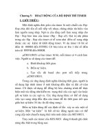
5-16
a = 36
in,
l = 72
in,
I = 13
in
4
,
E = 30
Mpsi
y =
F
1
a
2
6EI
(a − 3l) −
F
2
l
3
3EI
=
400(36)
2
(36 − 216)
6(30)(10
6
)(13)
−
400(72)
3
3(30)(10
6
)(13)
=−0.1675 in Ans.
5-17
I = 2(1.85) = 3.7in
4
Adding the weight of the channels,
2(5)/12 = 0.833 lbf/in,
y
A
=−
wl
4
8EI
−
Fl
3
3EI
=−
10.833(48
4
)
8(30)(10
6
)(3.7)
−
220(48
3
)
3(30)(10
6
)(3.7)
=−0.1378 in Ans.
A
a
D
C
F
B
a
E
A
shi20396_ch05.qxd 8/18/03 10:59 AM Page 112
Chapter 5 113
5-18
I = πd
4
/64 = π(2)
4
/64 = 0.7854 in
4
Tables A-9-5 and A-9-9
y =−
F
2
l
3
48EI
+
F
1
a
24EI
(4a
2
− 3l
2
)
=−
120(40)
3
48(30)(10
6
)(0.7854)
+
80(10)(400 − 4800)
24(30)(10
6
)(0.7854)
=−0.0130 in Ans.
5-19
(a) Useful relations
k =
F
y
=
48EI
l
3
I =
kl
3
48E
=
2400(48)
3
48(30)10
6
= 0.1843 in
4
From
I = bh
3
/12
h =
3
12(0.1843)
b
Form a table. First, Table A-17 gives likely available fractional sizes for b:
8
1
2
, 9, 9
1
2
, 10 in
For h:
1
2
,
9
16
,
5
8
,
11
16
,
3
4
For available b what is necessary h for required I?
(b)
I = 9(0.625)
3
/12 = 0.1831 in
4
k =
48EI
l
3
=
48(30)(10
6
)(0.1831)
48
3
= 2384 lbf/in
F =
4σ I
cl
=
4(90 000)(0.1831)
(0.625/2)(48)
= 4394 lbf
y =
F
k
=
4394
2384
= 1.84 in Ans.
choose 9"
×
5
8
"
Ans.
b
3
12(0.1843)
b
8.5 0.638
9.0 0.626
←
9.5 0.615
10.0 0.605
shi20396_ch05.qxd 8/18/03 10:59 AM Page 113
114 Solutions Manual • Instructor’s Solution Manual to Accompany Mechanical Engineering Design
5-20
Torque = (600 −80)(9/2) = 2340 lbf · in
(T
2
− T
1
)
12
2
= T
2
(1 − 0.125)(6) = 2340
T
2
=
2340
6(0.875)
= 446 lbf, T
1
= 0.125(446) = 56 lbf
M
0
= 12(680) − 33(502) + 48R
2
= 0
R
2
=
33(502) − 12(680)
48
= 175 lbf
R
1
= 680 − 502 + 175 = 353 lbf
We will treat this as two separate problems and then sum the results.
First, consider the 680 lbf load as acting alone.
z
OA
=−
Fbx
6EIl
(x
2
+ b
2
−l
2
); here b = 36
",
x = 12
",
l = 48
",
F = 680 lbf
Also,
I =
πd
4
64
=
π(1.5)
4
64
= 0.2485 in
4
z
A
=−
680(36)(12)(144 + 1296 − 2304)
6(30)(10
6
)(0.2485)(48)
=+0.1182 in
z
AC
=−
Fa(l − x)
6EIl
(x
2
+ a
2
− 2lx)
where
a = 12
" and
x = 21 + 12 = 33
"
z
B
=−
680(12)(15)(1089 + 144 − 3168)
6(30)(10
6
)(0.2485)(48)
=+0.1103 in
Next, consider the 502 lbf load as acting alone.
680 lbf
A
C
B
O
R
1
ϭ 510 lbf R
2
ϭ 170 lbf
12" 21" 15"
z
x
R
2
ϭ 175 lbf680 lbf
AC
BO
R
1
ϭ 353 lbf
502 lbf
12" 21" 15"
z
x
shi20396_ch05.qxd 8/18/03 10:59 AM Page 114
Chapter 5 115
z
OB
=
Fbx
6EIl
(x
2
+ b
2
−l
2
), where b = 15
"
,
x = 12
",
l = 48
",
I = 0.2485 in
4
Then,
z
A
=
502(15)(12)(144 + 225 − 2304)
6(30)(10
6
)(0.2485)(48)
=−0.081 44 in
For
z
B
use
x = 33
"
z
B
=
502(15)(33)(1089 +225 −2304)
6(30)(10
6
)(0.2485)(48)
=−0.1146 in
Therefore, by superposition
z
A
=+0.1182 −0.0814 =+0.0368 in Ans.
z
B
=+0.1103 −0.1146 =−0.0043 in Ans.
5-21
(a) Calculate torques and moment of inertia
T = (400 −50)(16/2) = 2800 lbf ·in
(8T
2
− T
2
)(10/2) = 2800 ⇒ T
2
= 80 lbf, T
1
= 8(80) = 640 lbf
I =
π
64
(1.25
4
) = 0.1198 in
4
Due to 720 lbf, flip beam A-9-6 such that
y
AB
→ b = 9, x = 0, l = 20, F =−720 lbf
θ
B
=
dy
dx
x=0
=−
Fb
6EIl
(3x
2
+ b
2
−l
2
)
=−
−720(9)
6(30)(10
6
)(0.1198)(20)
(0 + 81 −400) =−4.793(10
−3
) rad
y
C
=−12θ
B
=−0.057 52 in
Due to 450 lbf, use beam A-9-10,
y
C
=−
Fa
2
3EI
(l +a) =−
450(144)(32)
3(30)(10
6
)(0.1198)
=−0.1923 in
450 lbf720 lbf
9" 11" 12"
O
y
A
B
C
R
O
R
B
A
CB
O
R
1
R
2
12"
502 lbf
21" 15"
z
x
shi20396_ch05.qxd 8/18/03 10:59 AM Page 115
116 Solutions Manual • Instructor’s Solution Manual to Accompany Mechanical Engineering Design
Adding the two deflections,
y
C
=−0.057 52 − 0.1923 =−0.2498 in Ans.
(b) At O:
Due to 450 lbf:
dy
dx
x=0
=
Fa
6EIl
(l
2
− 3x
2
)
x=0
=
Fal
6EI
θ
O
=−
720(11)(0 + 11
2
− 400)
6(30)(10
6
)(0.1198)(20)
+
450(12)(20)
6(30)(10
6
)(0.1198)
= 0.010 13 rad = 0.5805
◦
At B:
θ
B
=−4.793(10
−3
) +
450(12)
6(30)(10
6
)(0.1198)(20)
[20
2
− 3(20
2
)]
=−0.014 81 rad = 0.8485
◦
I = 0.1198
0.8485
◦
0.06
◦
= 1.694 in
4
d =
64I
π
1/4
=
64(1.694)
π
1/4
= 2.424 in
Use
d = 2.5in Ans.
I =
π
64
(2.5
4
) = 1.917 in
4
y
C
=−0.2498
0.1198
1.917
=−0.015 61 in Ans.
5-22
(a)
l = 36(12) = 432 in
y
max
=−
5wl
4
384EI
=−
5(5000/12)(432)
4
384(30)(10
6
)(5450)
=−1.16 in
The frame is bowed up 1.16 in with respect to the bolsters. It is fabricated upside down
and then inverted. Ans.
(b) The equation in xy-coordinates is for the center sill neutral surface
y =
wx
24EI
(2lx
2
− x
3
−l
3
) Ans.
y
x
l
shi20396_ch05.qxd 8/18/03 10:59 AM Page 116
Chapter 5 117
Differentiating this equation and solving for the slope at the left bolster gives
Thus,
dy
dx
=
w
24EI
(6lx
2
− 4x
3
−l
3
)
dy
dx
x=0
=−
wl
3
24EI
=−
(5000/12)(432)
3
24(30)(10
6
)(5450)
=−0.008 57
The slope at the right bolster is 0.008 57, so equation at left end is
y =−0.008 57x
and
at the right end is
y = 0.008 57(x −l).
Ans.
5-23 From Table A-9-6,
y
L
=
Fbx
6EIl
(x
2
+ b
2
−l
2
)
y
L
=
Fb
6EIl
(x
3
+ b
2
x −l
2
x)
dy
L
dx
=
Fb
6EIl
(3x
2
+ b
2
−l
2
)
dy
L
dx
x=0
=
Fb(b
2
−l
2
)
6EIl
Let
ξ =
Fb(b
2
−l
2
)
6EIl
And set
I =
πd
4
L
64
And solve for
d
L
d
L
=
32Fb(b
2
−l
2
)
3π Elξ
1/4
Ans.
For the other end view, observe the figure of Table A-9-6 from the back of the page, noting
that a and b interchange as do x and −x
d
R
=
32Fa(l
2
− a
2
)
3π Elξ
1/4
Ans.
For a uniform diameter shaft the necessary diameter is the larger of
d
L
and
d
R
.
shi20396_ch05.qxd 8/18/03 10:59 AM Page 117
118 Solutions Manual • Instructor’s Solution Manual to Accompany Mechanical Engineering Design
5-24 Incorporating a design factor into the solution for
d
L
of Prob. 5-23,
d =
32n
3π Elξ
Fb(l
2
− b
2
)
1/4
=
(mm 10
−3
)
kN mm
3
GPa mm
10
3
(10
−9
)
10
9
(10
−3
)
1/4
d = 4
32(1.28)(3.5)(150)|(250
2
− 150
2
)|
3π(207)(250)(0.001)
10
−12
= 36.4mm Ans.
5-25 The maximum occurs in the right section. Flip beam A-9-6 and use
y =
Fbx
6EIl
(x
2
+ b
2
−l
2
)
where
b = 100 mm
dy
dx
=
Fb
6EIl
(3x
2
+ b
2
−l
2
) = 0
Solving for x,
x =
l
2
− b
2
3
=
250
2
− 100
2
3
= 132.29 mm from right
y =
3.5(10
3
)(0.1)(0.132 29)
6(207)(10
9
)(π/64)(0.0364
4
)(0.25)
[0.132 29
2
+ 0.1
2
− 0.25
2
](10
3
)
=−0.0606 mm Ans.
5-26
x
y
z
F
1
a
2
b
2
b
1
a
1
F
2
3.5 kN
100
250
150
d
The slope at
x = 0
due to
F
1
in the xy plane is
θ
xy
=
F
1
b
1
b
2
1
−l
2
6EIl
and in the xz plane due to
F
2
is
θ
xz
=
F
2
b
2
b
2
2
−l
2
6EIl
For small angles, the slopes add as vectors. Thus
θ
L
=
θ
2
xy
+ θ
2
xz
1/2
=
F
1
b
1
b
2
1
−l
2
6EIl
2
+
F
2
b
2
b
2
2
−l
2
6EIl
2
1/2
shi20396_ch05.qxd 8/18/03 10:59 AM Page 118
Chapter 5 119
Designating the slope constraint as
ξ,
we then have
ξ =|θ
L
|=
1
6EIl
F
i
b
i
b
2
i
−l
2
2
1/2
Setting
I = πd
4
/64
and solving for d
d =
32
3π Elξ
F
i
b
i
b
2
i
−l
2
2
1/2
1/4
For the LH bearing,
E = 30
Mpsi,
ξ = 0.001, b
1
= 12, b
2
= 6
,and
l = 16.
The result is
d
L
=
1.31 in.
Using a similar flip beam procedure, we get
d
R
= 1.36
in for the RH bearing.
So use
d = 13/8
in Ans.
5-27 For the xy plane, use y
BC
of Table A-9-6
y =
100(4)(16 −8)
6(30)(10
6
)(16)
[8
2
+ 4
2
− 2(16)8] =−1.956(10
−4
)in
For the xz plane use y
AB
z =
300(6)(8)
6(30)(10
6
)(16)
[8
2
+ 6
2
− 16
2
] =−7.8(10
−4
)in
δ
= (−1.956j − 7.8k)(10
−4
)in
|δ|=8.04(10
−4
)in Ans.
5-28
d
L
=
32n
3π Elξ
F
i
b
i
b
2
i
−l
2
2
1/2
1/4
=
32(1.5)
3π(29.8)(10
6
)(10)(0.001)
[800(6)(6
2
− 10
2
)]
2
+ [600(3)(3
2
− 10
2
)]
2
1/2
1/4
= 1.56 in
d
R
=
32(1.5)
3π(29.8)(10
6
)(10)(0.001)
[800(4)(10
2
− 4
2
)]
2
+ [600(7)(10
2
− 7
2
)]
2
1/2
1/4
= 1.56 in choose d ≥ 1.56 in Ans.
5-29 From Table A-9-8 we have
y
L
=
M
B
x
6EIl
(x
2
+ 3a
2
− 6al +2l
2
)
dy
L
dx
=
M
B
6EIl
(3x
2
+ 3a
2
− 6al +2l
2
)
shi20396_ch05.qxd 8/18/03 10:59 AM Page 119
120 Solutions Manual • Instructor’s Solution Manual to Accompany Mechanical Engineering Design
At
x = 0,
the LH slope is
θ
L
=
dy
L
dx
=
M
B
6EIl
(3a
2
− 6al +2l
2
)
from which
ξ =
|
θ
L
|
=
M
B
6EIl
(l
2
− 3b
2
)
Setting
I = πd
4
/64
and solving for d
d =
32M
B
(l
2
− 3b
2
)
3π Elξ
1/4
For a multiplicity of moments, the slopes add vectorially and
d
L
=
32
3π Elξ
M
i
l
2
− 3b
2
i
2
1/2
1/4
d
R
=
32
3π Elξ
M
i
3a
2
i
−l
2
2
1/2
1/4
The greatest slope is at the LH bearing. So
d =
32(1200)[9
2
− 3(4
2
)]
3π(30)(10
6
)(9)(0.002)
1/4
= 0.706 in
So use
d = 3/4in Ans.
5-30
6F
AC
= 18(80)
F
AC
= 240 lbf
R
O
= 160 lbf
I =
1
12
(0.25)(2
3
) = 0.1667 in
4
Initially, ignore the stretch of
AC.
From Table A-9-10
y
B1
=−
Fa
2
3EI
(l +a) =−
80(12
2
)
3(10)(10
6
)(0.1667)
(6 + 12) =−0.041 47 in
Stretch of AC:
δ =
FL
AE
AC
=
240(12)
(π/4)
(
1/2
)
2
(10)(10
6
)
= 1.4668(10
−3
)in
Due to stretch of AC
By superposition,
y
B2
=−3δ =−4.400(10
−3
)in
y
B
=−0.041 47 − 0.0044 =−0.045 87 in Ans.
80 lbfF
AC
126
B
R
O
shi20396_ch05.qxd 8/18/03 10:59 AM Page 120
Chapter 5 121
5-31
θ =
TL
JG
=
(0.1F)(1.5)
(π/32)(0.012
4
)(79.3)(10
9
)
= 9.292(10
−4
)F
Due to twist
δ
B1
= 0.1(θ ) = 9.292(10
−5
)F
Due to bending
δ
B2
=
FL
3
3EI
=
F(0.1
3
)
3(207)(10
9
)(π/64)(0.012
4
)
= 1.582(10
−6
)F
δ
B
= 1.582(10
−6
)F +9.292(10
−5
)F = 9.450(10
−5
)F
k =
1
9.450(10
−5
)
= 10.58(10
3
) N/m = 10.58 kN/m Ans.
5-32
R
1
=
Fb
l
R
2
=
Fa
l
δ
1
=
R
1
k
1
δ
2
=
R
2
k
2
Spring deflection
y
S
=−δ
1
+
δ
1
− δ
2
l
x =−
Fb
k
1
l
+
Fb
k
1
l
2
−
Fa
k
2
l
2
x
y
AB
=
Fbx
6EIl
(x
2
+ b
2
−l
2
) +
Fx
l
2
b
k
1
−
a
k
2
−
Fb
k
1
l
Ans.
y
BC
=
Fa(l − x)
6EIl
(x
2
+ a
2
− 2lx) +
Fx
l
2
b
k
1
−
a
k
2
−
Fb
k
1
l
Ans.
5-33 See Prob. 5-32 for deflection due to springs. Replace
Fb/l
and
Fa/l
with
wl/2
y
S
=−
wl
2k
1
+
wl
2k
1
l
−
wl
2k
2
l
x =
wx
2
1
k
1
+
1
k
2
−
wl
2k
1
y =
wx
24EI
(2lx
2
− x
3
−l
3
) +
wx
2
1
k
1
+
1
k
2
−
wl
2k
1
Ans.
F
baCAB
l
R
2
␦
2
␦
1
R
1
shi20396_ch05.qxd 8/18/03 10:59 AM Page 121
122 Solutions Manual • Instructor’s Solution Manual to Accompany Mechanical Engineering Design
5-34 Let the load be at
x > l/2
. The maximum deflection will be in Section AB (Table A-9-10)
y
AB
=
Fbx
6EIl
(x
2
+ b
2
−l
2
)
dy
AB
dx
=
Fb
6EIl
(3x
2
+ b
2
−l
2
) = 0 ⇒ 3x
2
+ b
2
−l
2
= 0
x =
l
2
− b
2
3
,
x
max
=
l
2
3
= 0.577lAns.
For
x < l/2 x
min
= l − 0.577l = 0.423lAns.
5-35
M
O
= 50(10)(60) + 600(84)
= 80 400 lbf ·in
R
O
= 50(10) + 600 = 1100 lbf
I = 11.12 in
4
from Prob. 5-12
M =−80 400 + 1100x −
4.167x
2
2
− 600x −84
1
EI
dy
dx
=−80 400x +550x
2
− 0.6944x
3
− 300x −84
2
+ C
1
dy
dx
= 0 at x = 0 І
C
1
= 0
EIy =−402 00x
2
+ 183.33x
3
− 0.1736x
4
− 100x −84
3
+ C
2
y = 0atx = 0 І
C
2
= 0
y
B
=
1
30(10
6
)(11.12)
[−40 200(120
2
) + 183.33(120
3
)
− 0.1736(120
4
) − 100(120 − 84)
3
]
=−0.9075 in Ans.
5-36 See Prob. 5-13 for reactions:
R
O
= 860 lbf, R
C
= 540 lbf
M = 860x − 800x − 36
1
− 600x −60
1
EI
dy
dx
= 430x
2
− 400x −36
2
− 300x −60
2
+ C
1
EIy = 143.33x
3
− 133.33x − 36
3
− 100x −60
3
+ C
1
x +C
2
y = 0atx = 0 ⇒ C
2
= 0
y = 0atx = 120 in ⇒ C
1
=−1.2254(10
6
) lbf ·in
2
Substituting
C
1
and
C
2
and evaluating at
x = 60,
EIy = 30(10
6
)I
−
1
16
= 143.33(60
3
) − 133.33(60 −36)
3
− 1.2254(10
6
)(60)
I = 23.68 in
4
Agrees with Prob. 5-13. The rest of the solution is the same.
10'
7'
R
O
600 lbf
50 lbf/ft
M
O
O
A
B
shi20396_ch05.qxd 8/18/03 10:59 AM Page 122
Chapter 5 123
5-37
I = 0.2485 in
4
R
O
= 12(20) +
24
40
(300) = 420 lbf
M = 420x −
12
2
x
2
− 300x −16
1
EI
dy
dx
= 210x
2
− 2x
3
− 150x −16
2
+ C
1
EIy = 70x
3
− 0.5x
4
− 50x −16
3
+ C
1
x +C
2
y = 0atx = 0 ⇒ C
2
= 0
y = 0atx = 40 in ⇒ C
1
=−6.272(10
4
) lbf ·in
2
Substituting for
C
1
and
C
2
and evaluating at
x = 16,
y
A
=
1
30(10
6
)(0.2485)
[70(16
3
) − 0.5(16
4
) − 6.272(10
4
)(16)]
=−0.1006 in Ans.
y|
x=20
=
1
30(10
6
)(0.2485)
[70(20
3
) − 0.5(20
4
) − 50(20 − 16)
3
− 6.272(10
4
)(20)]
= 0.1043 in Ans.
3.7% difference Ans.
5-38
R
1
=
w[(l + a)/2][(l −a)/2)]
l
=
w
4l
(l
2
− a
2
)
R
2
=
w
2
(l +a) −
w
4l
(l
2
− a
2
) =
w
4l
(l +a)
2
M =
w
4l
(l
2
− a
2
)x −
wx
2
2
+
w
4l
(l +a)
2
x −l
1
EI
dy
dx
=
w
8l
(l
2
− a
2
)x
2
−
w
6
x
3
+
w
8l
(l +a)
2
x −l
2
+ C
1
EIy =
w
24l
(l
2
− a
2
)x
3
−
w
24
x
4
+
w
24l
(l +a)
2
x −l
3
+ C
1
x +C
2
y = 0atx = 0 ⇒ C
2
= 0
y = 0atx = l
0 =
w
24l
(l
2
− a
2
)l
3
−
w
24
l
4
+ C
1
l ⇒ C
1
=
wa
2
l
24
y =
w
24EIl
[(l
2
− a
2
)x
3
−lx
4
+ (l +a)
2
x −l
3
+ a
2
l
2
x] Ans.
a
w
l ϩ a
2
l Ϫ a
2
shi20396_ch05.qxd 8/18/03 10:59 AM Page 123
124 Solutions Manual • Instructor’s Solution Manual to Accompany Mechanical Engineering Design
5-39 From Prob. 5-15,
R
A
= R
B
= 120 lbf
, and
I = 0.105 47 in
4
First half of beam,
M =−120x + 120x − 10
1
EI
dy
dx
=−60x
2
+ 60x −10
2
+ C
1
dy/dx = 0
at
x = 20 in ⇒ 0 =−60(20
2
) + 60(20 −10)
2
+ C
1
⇒ C
1
= 1.8(10
4
) lbf ·in
2
EIy =−20x
3
+ 20x −10
3
+ 1.8(10
4
)x +C
2
y = 0
at
x = 10 in ⇒ C
2
=−1.6(10
5
) lbf ·in
3
y|
x=0
=
1
30(10
6
)(0.105 47)
(−1.6)(10
5
)
=−0.050 57 in Ans.
y|
x=20
=
1
30(10
6
)(0.105 47)
[−20(20
3
) + 20(20 − 10)
3
+ 1.8(10
4
)(20) − 1.6(10
5
)]
= 0.018 96 in Ans.
5-40 From Prob. 5-30,
R
O
= 160 lbf ↓, F
AC
= 240 lbf I = 0.1667 in
4
M =−160x + 240x − 6
1
EI
dy
dx
=−80x
2
+ 120x −6
2
+ C
1
EIy =−26.67x
3
+ 40x −6
3
+ C
1
x +C
2
y = 0atx = 0 ⇒ C
2
= 0
y
A
=−
FL
AE
AC
=−
240(12)
(π/4)(1/2)
2
(10)(10
6
)
=−1.4668(10
−3
)in
at
x = 6
10(10
6
)(0.1667)(−1.4668)(10
−3
) =−26.67(6
3
) + C
1
(6)
C
1
= 552.58 lbf ·in
2
y
B
=
1
10(10
6
)(0.1667)
[−26.67(18
3
) + 40(18 − 6)
3
+ 552.58(18)]
=−0.045 87 in Ans.
5-41
I
1
=
π
64
(1.5
4
) = 0.2485 in
4
I
2
=
π
64
(2
4
) = 0.7854 in
4
R
1
=
200
2
(12) = 1200 lbf
For
0 ≤ x ≤ 16 in, M = 1200x −
200
2
x −4
2
x
M
ր
I
shi20396_ch05.qxd 8/18/03 10:59 AM Page 124
Chapter 5 125
M
I
=
1200x
I
1
− 4800
1
I
1
−
1
I
2
x −4
0
− 1200
1
I
1
−
1
I
2
x −4
1
−
100
I
2
x −4
2
= 4829x − 13 204x − 4
0
− 3301.1x − 4
1
− 127.32x − 4
2
E
dy
dx
= 2414.5x
2
− 13 204x −4
1
− 1651x −4
2
− 42.44x −4
3
+ C
1
Boundary Condition:
dy
dx
= 0
at x = 10 in
0 = 2414.5(10
2
) − 13 204(10 − 4)
1
− 1651(10 − 4)
2
− 42.44(10 − 4)
3
+ C
1
C
1
=−9.362(10
4
)
Ey = 804.83x
3
− 6602x −4
2
− 550.3x −4
3
− 10.61x −4
4
− 9.362(10
4
)x +C
2
y = 0 at x = 0 ⇒ C
2
= 0
For
0 ≤ x ≤ 16 in
y =
1
30(10
6
)
[804.83x
3
− 6602x −4
2
− 550.3x −4
3
−10.61x − 4
4
− 9.362(10
4
)x]
Ans.
at x = 10 in
y|
x=10
=
1
30(10
6
)
[804.83(10
3
) − 6602(10 − 4)
2
− 550.3(10 − 4)
3
− 10.61(10 − 4)
4
− 9.362(10
4
)(10)]
=−0.016 72 in Ans.
5-42 Define
δ
ij
as the deflection in the direction of the load at station i due to a unit load at station j.
If U is the potential energy of strain for a body obeying Hooke’s law, apply P
1
first. Then
U =
1
2
P
1
( P
1
δ
11
)
When the second load is added, U becomes
U =
1
2
P
1
( P
1
δ
11
) +
1
2
P
2
( P
2
δ
22
) + P
1
( P
2
δ
12
)
For loading in the reverse order
U
=
1
2
P
2
( P
2
δ
22
) +
1
2
P
1
( P
1
δ
11
) + P
2
( P
1
δ
21
)
Since the order of loading is immaterial
U = U
and
P
1
P
2
δ
12
= P
2
P
1
δ
21
when
P
1
= P
2
,δ
12
= δ
21
which states that the deflection at station 1 due to a unit load at station 2 is the same as the
deflection at station 2 due to a unit load at 1.
δ
is sometimes called an influence coefficient.
shi20396_ch05.qxd 8/18/03 10:59 AM Page 125
126 Solutions Manual • Instructor’s Solution Manual to Accompany Mechanical Engineering Design
5-43
(a) From Table A-9-10
y
AB
=
Fcx(l
2
− x
2
)
6EIl
δ
12
=
y
F
x=a
=
ca(l
2
− a
2
)
6EIl
y
2
= Fδ
21
= Fδ
12
=
Fca(l
2
− a
2
)
6EIl
Substituting
I =
πd
4
64
y
2
=
400(7)(9)(23
2
− 9
2
)(64)
6(30)(10
6
)(π)(2)
4
(23)
= 0.00347 in Ans.
(b) The slope of the shaft at left bearing at
x = 0
is
θ =
Fb(b
2
−l
2
)
6EIl
Viewing the illustration in Section 6 of Table A-9 from the back of the page provides
the correct view of this problem. Noting that a is to be interchanged with b and
−x
with x leads to
θ =
Fa(l
2
− a
2
)
6EIl
=
Fa(l
2
− a
2
)(64)
6Eπd
4
l
θ =
400(9)(23
2
− 9
2
)(64)
6(30)(10
6
)(π)(2)
4
(23)
= 0.000 496 in/in
So
y
2
= 7θ = 7(0.000 496) = 0.00347 in Ans.
5-44 Place a dummy load Q at the center. Then,
M =
wx
2
(l − x) +
Qx
2
U = 2
l/2
0
M
2
dx
2EI
, y
max
=
∂U
∂ Q
Q=0
y
max
= 2
l/2
0
2M
2EI
∂ M
∂ Q
dx
Q=0
y
max
=
2
EI
l/2
0
wx
2
(l − x) +
Qx
2
x
2
dx
Q=0
Set
Q = 0
and integrate
400 lbf
9"
a
AB
c
21
x
b
7"
23"
y
shi20396_ch05.qxd 8/18/03 10:59 AM Page 126
Chapter 5 127
y
max
=
w
2EI
lx
3
3
−
x
4
4
l/2
0
y
max
=
5wl
4
384EI
Ans.
5-45
I = 2(1.85) = 3.7in
4
Adding weight of channels of
0.833 lbf ·in,
M =−Fx −
10.833
2
x
2
=−Fx − 5.417x
2
∂ M
∂ F
=−x
δ
B
=
1
EI
48
0
M
∂ M
∂ F
dx =
1
EI
48
0
(Fx + 5.417x
2
)(x) dx
=
(220/3)(48
3
) + (5.417/4)(48
4
)
30(10
6
)(3.7)
= 0.1378 in in direction of 220 lbf
І
y
B
=−0.1378 in Ans.
5-46
I
OB
=
1
12
(0.25)(2
3
) = 0.1667 in
4
, A
AC
=
π
4
1
2
2
= 0.196 35 in
2
F
AC
= 3F,
∂ F
AC
∂ F
= 3
right left
M =−F ¯xM=−2Fx
∂ M
∂ F
=−¯x
∂ M
∂ F
=−2x
U =
1
2EI
l
0
M
2
dx +
F
2
AC
L
AC
2A
AC
E
δ
B
=
∂U
∂ F
=
1
EI
l
0
M
∂ M
∂ F
dx +
F
AC
(∂ F
AC
/∂ F)L
AC
A
AC
E
=
1
EI
12
0
−F ¯x(−¯x) d ¯x +
6
0
(−2Fx)(−2x) dx
+
3F(3)(12)
A
AC
E
=
1
EI
F
3
(12
3
) + 4F
6
3
3
+
108F
A
AC
E
=
864F
EI
+
108F
A
AC
E
=
864(80)
10(10
6
)(0.1667)
+
108(80)
0.196 35(10)(10
6
)
= 0.045 86 in Ans.
F
AC
ϭ 3F
O
AB
F2F
x
6" 12"
x
¯
shi20396_ch05.qxd 8/18/03 10:59 AM Page 127
128 Solutions Manual • Instructor’s Solution Manual to Accompany Mechanical Engineering Design
5-47
Torsion
T = 0.1F
∂T
∂ F
= 0.1
Bending
M =−F ¯x
∂ M
∂ F
=−¯x
U =
1
2EI
M
2
dx +
T
2
L
2JG
δ
B
=
∂U
∂ F
=
1
EI
M
∂ M
∂ F
dx +
T (∂T /∂ F)L
JG
=
1
EI
0.1
0
−F ¯x(−¯x) d ¯x +
0.1F(0.1)(1.5)
JG
=
F
3EI
(0.1
3
) +
0.015F
JG
Where
I =
π
64
(0.012)
4
= 1.0179(10
−9
)m
4
J = 2I = 2.0358(10
−9
)m
4
δ
B
= F
0.001
3(207)(10
9
)(1.0179)(10
−9
)
+
0.015
2.0358(10
−9
)(79.3)(10
9
)
= 9.45(10
−5
)F
k =
1
9.45(10
−5
)
= 10.58(10
3
) N/m = 10.58 kN/m Ans.
5-48 From Prob. 5-41,
I
1
= 0.2485 in
4
, I
2
= 0.7854 in
4
For a dummy load
↑Q
at the center
0 ≤ x ≤ 10 in
M = 1200x −
Q
2
x −
200
2
x −4
2
,
∂ M
∂ Q
=
−x
2
y|
x=10
=
∂U
∂ Q
Q=0
=
2
E
1
I
1
4
0
(1200x)
−
x
2
dx +
1
I
2
10
4
[1200x − 100(x − 4)
2
]
−
x
2
dx
=
2
E
−
200(4
3
)
I
1
−
1.566(10
5
)
I
2
=−
2
30(10
6
)
1.28(10
4
)
0.2485
+
1.566(10
5
)
0.7854
=−0.016 73 in Ans.
x
F
shi20396_ch05.qxd 8/18/03 10:59 AM Page 128
Chapter 5 129
5-49
AB
M = Fx
∂ M
∂ F
= x
OA
N =
3
5
F
∂ N
∂ F
=
3
5
T =
4
5
Fa
∂T
∂ F
=
4
5
a
M
1
=
4
5
F ¯x
∂ M
1
∂ F
=
4
5
¯x
M
2
=
3
5
Fa
∂ M
2
∂ F
=
3
5
a
δ
B
=
∂u
∂ F
=
1
EI
a
0
Fx(x) dx +
(3/5)F(3/5)l
AE
+
(4/5)Fa(4a/5)l
JG
+
1
EI
l
0
4
5
F ¯x
4
5
¯x
d ¯x +
1
EI
l
0
3
5
Fa
3
5
a
d ¯x
=
Fa
3
3EI
+
9
25
Fl
AE
+
16
25
Fa
2
l
JG
+
16
75
Fl
3
EI
+
9
25
Fa
2
l
EI
I =
π
64
d
4
, J = 2I, A =
π
4
d
2
δ
B
=
64Fa
3
3Eπd
4
+
9
25
4Fl
πd
2
E
+
16
25
32Fa
2
l
πd
4
G
+
16
75
64Fl
3
Eπ d
4
+
9
25
64Fa
2
l
Eπ d
4
=
4F
75π Ed
4
400a
3
+ 27ld
2
+ 384a
2
l
E
G
+ 256l
3
+ 432a
2
l
Ans.
a
O
B
A
F
3
5
F
4
5
a
B
x
A
F
3
5
F
4
5
O
l
l
A
F
3
5
Fa
3
5
Fa
4
5
F
4
5
x
shi20396_ch05.qxd 8/18/03 10:59 AM Page 129
130 Solutions Manual • Instructor’s Solution Manual to Accompany Mechanical Engineering Design
5-50 The force applied to the copper and steel wire assembly is
F
c
+ F
s
= 250 lbf
Since
δ
c
= δ
s
F
c
L
3(π/4)(0.0801)
2
(17.2)(10
6
)
=
F
s
L
(π/4)(0.0625)
2
(30)(10
6
)
F
c
= 2.825F
s
∴
3.825F
s
= 250 ⇒ F
s
= 65.36 lbf, F
c
= 2.825F
s
= 184.64 lbf
σ
c
=
184.64
3(π/4)(0.0801)
2
= 12 200 psi = 12.2 kpsi Ans.
σ
s
=
65.36
(π/4)(0.0625
2
)
= 21 300 psi = 21.3 kpsi Ans.
5-51
(a) Bolt stress
σ
b
= 0.9(85) = 76.5 kpsi Ans.
Bolt force
F
b
= 6(76.5)
π
4
(0.375
2
) = 50.69 kips
Cylinder stress
σ
c
=−
F
b
A
c
=−
50.69
(π/4)(4.5
2
− 4
2
)
=−15.19 kpsi Ans.
(b) Force from pressure
P =
π D
2
4
p =
π(4
2
)
4
(600) = 7540 lbf = 7.54 kip
F
x
= 0
P
b
+ P
c
= 7.54 (1)
Since
δ
c
= δ
b
,
P
c
L
(π/4)(4.5
2
− 4
2
)E
=
P
b
L
6(π/4)(0.375
2
)E
P
c
= 5.037P
b
(2)
Substituting into Eq. (1)
6.037P
b
= 7.54 ⇒ P
b
= 1.249 kip; and from Eq (2), P
c
= 6.291 kip
Using the results of (a) above, the total bolt and cylinder stresses are
σ
b
= 76.5 +
1.249
6(π/4)(0.375
2
)
= 78.4 kpsi Ans.
σ
c
=−15.19 +
6.291
(π/4)(4.5
2
− 4
2
)
=−13.3 kpsi Ans.
6 bolts
50.69 Ϫ P
c
50.69 ϩ P
b
x
P
ϭ 7.54 kip
shi20396_ch05.qxd 8/18/03 10:59 AM Page 130