Tài liệu Ducvietjsc.com.vn Advanced General-purpose Inverters SYSDRIVE RX Series Digital Operator Used to ppt
Bạn đang xem bản rút gọn của tài liệu. Xem và tải ngay bản đầy đủ của tài liệu tại đây (2.42 MB, 16 trang )
Advanced General-purpose Inverters
SYSDRIVE
RX
Series
Advanced General-purpose Inverters
SYSDRIVE
RX
Series
Nomenclature and Functions
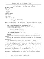
■ Inverter Nomenclature and Functions
Used to set parameters, perform various
monitoring, and start and stop the Inverter.
Displays relevant data, such as frequency
reference, output current, and set values.
Digital Operator
Data Display
Remove this cover when wiring the terminal block.
Terminal block Cover
Ducvietjsc.com.vn
Để biết thêm chi tiết xin liên hệ: ĐẠI LÝ ỦY QUYỀN TẠI VIỆT NAM
CÔNG TY CỔ PHẦN THƯƠNG MẠI CÔNG NGHỆ ĐỨC VIỆT
Số 17, ngõ 26/17, Nguyên Hồng, Đống Đa, Hà Nội.
Tel: (04) 773 6839; 773 6116 – Fax: (04) 773 6122
E-mail: ,
Website: Ducvietjsc.com.vn
Advanced General-purpose Inverters
SYSDRIVE
RX
Series
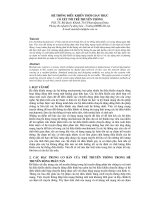
■ Part Names and Descriptions of the Digital Operator
Name Function
POWER LED indicator Lit when the power is supplied to the control circuit.
ALARM LED indicator Lit when an Inverter error occurs.
RUN (during RUN) LED
indicator
Lit when the Inverter is running.
PROGRAM LED indicator
Lit when the set value of each function is indicated on the data display.
Blinks during warning (when the set value is incorrect).
Data display Displays relevant data, such as frequency reference, output current, and set values.
Data display LED indicator
Lit according to the indication on the data display.
Hz: Frequency V: Voltage A: Current kW: Power %: Ratio
RUN command LED
indicator
Lit when the RUN command is set to the Digital Operator.
(The RUN key on the Digital Operator is available for operation)
RUN key
Activates the Inverter. Available only when operation via the Digital Operator is selected.
(Check that the RUN command LED indicator is lit.)
STOP/RESET key Decelerates and stops the Inverter. Functions as a reset key if an Inverter error occurs.
Mode key
Switches between: the monitor mode (d@@@), the basic function mode (F@@@), and the extended
function mode (A@@@, b@@@, c@@@, H@@@).
Enter key Enters the set value. (To change the set value, be sure to press the Enter key.)
Increment key Changes the mode. Also, increases the set value of each function.
Decrement key Changes the mode. Also, decreases the set value of each function.
8k8k8k8k
Data display
Operation keys
RUN command LED indicator
8.8.8.8.
Ducvietjsc.com.vn
Advanced General-purpose Inverters
SYSDRIVE
RX
Series
Using Digital Operator
■ Setting output frequency
Power ON
(1) 0.0 or the value previously
monitored is displayed.
(2) Function code appears.
(3) F001 appears.
(It continues in upper right.)
0.0k0k
Press key.
Ddk0k0k1k
Press until F001 appears.
Dfk0k0k1k
Press key.
(4) Preset value is displayed.
(5) Newly set value is displayed.
(6) Set end. (Back to F001)
D0.0k0k
Press to set desired value.
D6k0.0k0k
Press key to store the value.
Dfk0k0k1k
Ducvietjsc.com.vn
Advanced General-purpose Inverters
SYSDRIVE
RX
Series
■ Operation Example for Basic Display (factory default: "b037 = 04")
• Displays the limited basic parameters.
• Other parameters than those mentioned above are not displayed. To display all parameters, select "Complete display 'b037 = 00'".
● Parameters to be Displayed and Arrangement
* If the target parameter is not displayed, check the setting of display selection "b037".
To display all parameters, set "00" to "b037".
Monitor mode: All
Function mode: 4 parameters
Extended function mode: 20 parameters
No. Display code Item
1 d001 to d104 Monitor display
2 F001 Output frequency setting
3 F002 Acceleration time 1
4 F003 Deceleration time 1
5 F004 Digital Operator rotation direction Selection (RUN direction selection)
6 A001 Frequency reference selection
7 A002 RUN command selection
8 A003 Base frequency
9 A004 Maximum frequency
10 A005 FV/FI terminal selection
11 A020 Multi-step speed reference 0
12 A021 Multi-step speed reference 1
13 A023 Multi-step speed reference 2
14 A044 V/f characteristics selection
15 A045 Output voltage gain
16 A085 Energy-saving RUN mode selection
17 b001 Retry selection
18 b002 Allowable momentary power interruption time
19 b008 Trip retry selection
20 b011 Trip retry wait time
21 b037 Display selection *
22 b083 Carrier frequency
23 b084 Initialization selection
24 b130 Overvoltage protection function during deceleration
25 b131 Overvoltage protection level during deceleration
26 C021 Multi-function output terminal P1 selection
27 C022 Multi-function output terminal P2 selection
28 C036 Relay output (MA, MB) contact selection
Ducvietjsc.com.vn
Advanced General-purpose Inverters
SYSDRIVE
RX
Series
Standard Specification List
●Three-phase 200-V Class
●Three-phase 400-V Class
Class 3-phase 200 V
Model name (3G3RX-) A2055 A2075 A2110 A2150 A2185 A2220 A2300 A2370 A2450 A2550
Max. applicable motor
4P
kW 5.5 7.5 11 15 18.5 22 30 37 45 55
Rated output capacity
(kVA)
200 V 8.3 11.0 15.9 22.1 26.3 32.9 41.9 50.2 63.0 76.2
240 V 9.9 13.3 19.1 26.6 31.5 39.4 50.2 60.2 75.6 91.4
Rated input voltage 3-phase (3-wire) 200 V −15% to 240 V +10%, 50/60 Hz ±5%
Rated output voltage 3-phase: 200 to 240 V (Cannot exceed that of incoming voltage.)
Rated output current (A) 24 32 46 64 76 95 121 145 182 220
Weight (kg) 6 6 6 14 14 14 22 30 30 43
Braking
Regenerative braking
Built-in braking resistor circuit
(discharge resistor separately mounted)
Regenerative braking unit separately mounted
Minimum connection
resistance (Ω)
17 17 17 7.5 7.5 5
Class 3-phase 400 V
Model name (3G3RX-) A4055 A4075 A4110 A4150 A4185 A4220 A4300 A4370 A4450 A4550
Max. applicable motor
4P
kW 5.5 7.5 11 15 18.5 22 30 37 45 55
Rated output capacity
(kVA)
400 V 9.7 13.1 17.3 22.1 26.3 33.2 40.1 51.9 63.0 77.6
480 V 11.6 15.8 20.7 26.6 31.5 39.9 48.2 62.3 75.6 93.1
Rated input voltage 3-phase (3-wire) 380 V −15% to 480 V +10%, 50/60 Hz ±5%
Rated output voltage 3-phase: 380 to 480 V (Cannot exceed that of incoming voltage.)
Rated output current (A) 14 19 25 32 38 48 58 75 91 112
Weight (kg) 6 6 6 14 14 14 22 30 30 30
Braking
Regenerative braking Built-in braking resistor circuit (discharge resistor) Regenerative braking unit separately mounted
Minimum connection
resistance (Ω)
70 35 35 24 24 20
Ducvietjsc.com.vn
Advanced General-purpose Inverters
SYSDRIVE
RX
Series
Common Specification
Item
Specifications
Enclosure rating IP20
Cooling method Forced air cooling
Control method Phase-to-phase sinusoidal modulation PWM
Output frequency range 0.1 to 400Hz
Frequency precision
Digital command: ±0.01% of the max. frequency
Analog command: ±0.2% of the max. frequency (25°C ±10°C)
Frequency resolution
Digital setting: 0.01 Hz
Analog setting: Max. frequency/4000
(Terminal FV: 12 bits/0 to +10 V), (Terminal FV2: 12 bits/−10 to +10 V),
(Terminal FI: 12 bits/0 to +20 mA)
Voltage/Frequency characteristics
V/f optionally changeable at base frequencies of 30 to 400 Hz, V/f braking constant torque, reduction torque, sensorless
vector control, sensor-less vector control at 0 Hz
Speed fluctuation ±0.5% (under sensor-less vector control or sensorless vector control at 0 Hz)
Overload current rating 150%/60 s, 200%/3 s
Acceleration/Deceleration time 0.01 to 3600.0 s (line/curve selection)
Starting torque
200%/0.3 Hz
(under sensorless vector control or sensor-less vector control at 0 Hz)
150%/Torque at 0 Hz (under sensor-less vector control at 0 Hz, or when the motor with one frame fewer than the
maximum applicable motor is connected)
DC injection braking
Operates when the starting frequency is lower than that in deceleration via the STOP command, when the frequency
reference is lower than the operation frequency, or via an external input (braking power, time, and frequency settable)
Input
Multi-function input
8 terminals, NO/NC switchable, sink/source logic switchable
[Terminal function] 8 functions can be selected from among 60.
Reverse (RV), Multi-step speed 1 (CF1), Multi-step speed 2 (CF2), Multi-step speed 3 (CF3), Multi-step speed 4 (CF4),
Jogging (JG), External DC injection braking (DB), 2nd control (SET), 2-step acceleration/deceleration (2CH), Free-run
stop (FRS), External trip (EXT), USP function (USP), Commercial switch (CS), Soft lock (SFT), Analog input selection
(AT), 3rd control (SET3), Reset (RS), 3-wire startup (STA), 3-wire stop (STP), 3-wire forward/reverse (F/R), PID disabled
(PID), PID integral reset (PIDC), Control gain switching (CAS), Remote operation accelerated (UP), Remote operation
decelerated (DWN), Remote operation data clear (UDC), Forced operator (OPE), Multi-step speed bit 1 (SF1),
Multi-step speed bit 2 (SF2), Multi-step speed bit 3 (SF3), Multi-step speed bit 4 (SF4), Multi-step speed bit 5 (SF5),
Multi-step speed bit 6 (SF6), Multi-step speed bit 7 (SF7), Overload limit switching (OLR), Torque limit enabled (TL),
Torque limit switching 1 (TRQ1), Torque limit switching 2 (TRQ2), P/PI switching (PPI), Brake confirmation (BOK),
Orientation (ORT), LAD cancel (LAC), Position deviation clear (PCLR), Pulse train position command input permission
(STAT), Frequency addition function (ADD), Forced terminal (F-TM), Torque reference input permission (ATR),
Integrated power clear (KHC), Servo ON (SON), Preliminary excitation (FOC), General-purpose input 1 (MI1),
General-purpose input 2 (MI2), General-purpose input 3 (MI3), General-purpose input 4 (MI4), General-purpose input 5
(MI5), General-purpose input 6 (MI6), General-purpose input 7 (MI7), General-purpose input 8 (MI8), Analog command
held (AHD), No allocation (no)
Thermistor input terminal 1 terminal (Positive/Negative temperature coefficient of resistance element switchable)
Output
Multi-function output
5 open collector output terminals: NO/NC switchable, sink/source logic switchable
1 relay (SPDT contact) output terminal: NO/NC switchable
[Terminal function] 6 functions can be selected from among 43.
During operation (RUN), Constant speed reached (FA1), Set frequency exceeded (FA2), Overload warning (OL),
Excessive PID deviation (OD), Alarm signal (AL), Set frequency only (FA3), Overtorque (OTQ), Signal during
momentary power interruption (IP), Signal during undervoltage (UV), Torque limit (TRQ), RUN time over (RNT),
Power ON time over (ONT), Thermal warning (THM), Brake release (BRK), Brake error (BER), Zero-speed signal (ZS),
Excessive speed deviation (DSE), Position ready (POK), Set frequency exceeded 2 (FA4), Set frequency only 2 (FA5),
Overload warning 2 (OL2), PID FB status output (FBV), Network error (NDc), Logic operation output 1 (LOG1), Logic
operation output 2 (LOG2), Logic operation output 3 (LOG3), Logic operation output 4 (LOG4), Logic operation output 5
(LOG5), Logic operation output 6 (LOG6), Capacitor life warning (WAC), Cooling fin overheat warning (WAF), Starting
contact signal (FR), Cooling fin overheat warning (OHF), Low current signal (LOC), General-purpose output 1 (MO1),
General-purpose output 2 (MO2), General-purpose output 3 (MO3), General-purpose output 4 (MO4), General-purpose
output 5 (MO5), General-purpose output 6 (MO6), Operation ready (IRDY), During forward operation (FWR),
During reverse operation (RVR), Fatal fault (MJA), Alarm codes 0 to 3 (AC0 to AC3)
Multi-function monitor
output terminal
Analog voltage output, Analog current output,
Pulse train output (A-F, D-F {multiplied by "n", pulse output only}, A, T, V, P, etc.)
Display monitor
Output frequency, Output current, Output torque, Frequency conversion value, Trip record, I/O terminal status,
Electric power, etc.
Other functions
V/f free setting (7), Upper/lower frequency limit, Frequency jump, Curve acceleration/deceleration, Manual torque boost
level/break, Energy-saving operation, Analog meter adjustment, Starting frequency, Carrier frequency adjustment,
Electronic thermal function, (free setting available), External start/end (frequency/rate), Analog input selection, Trip retry,
Restart during momentary power interruption, Various signal outputs, Reduced voltage startup, Overload limit,
Initialization value setting, Automatic deceleration at power-off, AVR function, Fuzzy acceleration/deceleration, Auto
tuning (Online/Offline), High-torque multi-operation control (sensor-less vector control of two monitors with one Inverter)
Carrier frequency modification range 0.5 to 15 kHz
Protective functions
Overcurrent protection, Overvoltage protection, Undervoltage protection, Electronic thermal protection, Temperature
error protection, Momentary power interruption/Power interruption protection, Input open-phase protection, Braking
resistor overload protection, Ground-fault overcurrent detection at power-on, USP error, External trip, Emergency shutoff
trip, CT error, Communication error, Option error, etc.
Ducvietjsc.com.vn
Advanced General-purpose Inverters
SYSDRIVE
RX
Series
*Complies with the test method specified in JIS C0040 (1999).
Note: Insulation distance complies with UL/CE standards.
Operating
environ-
ment
Ambient/Storage
temperature/Humidity
−10°C to 50°C/−20°C to 65°C/20% to 90% RH (with no condensation)
Vibration *
3G3RX-A055/-A075/-A110/-A150/-A185/-A220: 5.9 m/s
2
(0.6G), 10 to 55 Hz
3G3RX-A300/-A370/-A450/-A550: 2.94 m/s
2
(0.3G), 10 to 55 Hz
Location At a maximum altitude of 1,000 m; indoors (without corrosive gases or dust)
Options
Feedback option Sensor vector control
Digital input option 4-digit BCD, 16-bit binary
Other options
Braking resistor, AC reactor, DC reactor, Noise filter, Digital Operator cables, Harmonics suppression unit, LCR filter,
Analog operation panel, Application control device, Regenerative braking unit, etc.
Item
Specifications
Ducvietjsc.com.vn
Advanced General-purpose Inverters
SYSDRIVE
RX
Series
■ Terminal Block Specifications
● Terminal Block Position
Note: This illustration shows the terminal block with the Terminal block front cover removed.
● Arrangement of Main Circuit Terminals ●Emergency Shutoff Function
• The built-in slide switch is used to enable or disable the emer-
gency shutoff function (Factory Default: Disabled).
• This function is intended to turn off the Inverter output (Stop
switching the main element) via only the multi-function input
terminal of the hardware circuit, independent of the CPU Soft-
ware.
Digital Operator
Control circuit terminal block
Main circuit terminal block
Terminal
symbol
Terminal name Description
R/L1,
S/L2,
T/L3
Main power
supply input
terminal
Connect the input power supply.
U/T1,
V/T2,
W/T3
Inverter output
terminal
Connect to the 3-phase motor.
+1, P/+2
External DC
reactor
connection
terminal
Remove the short-circuit bar between terminals
"+1" and "P/+2", and connect the optional
power factor improvement reactor (DCL).
P/+2,
RB
Braking resistor
connection
terminals
Connect optional external braking resistors.
(The RB terminal is provided for the Inverters
with 22 kW or lower capacity.)
P/+2, N/-
Regenerative
braking unit
connection
terminal
Connect optional regenerative braking units.
G
Ground terminal
Inverter case ground terminal. Connect this
terminal to the ground.
Class D (200 V), Class D (400 V)
GG
Terminal arrangement
RO TO
RB
R/L1
S/L2
T/L3
+1
P/+2
N/-
U/T1
V/T2
W/T3
Ground terminal with
short-circuit bar (shaded area)
for EMC filter multi-function
switching
+1-P/+2 short-
circuit bar
When not using the DCL,
keep the +1-P/+2
short-circuit bar attached.
CHARGE LED indicator
EMC filter enabled EMC filter disabled (factory default)
EMC filter functions switching method
ON
Slide switch SW1
Slide lever (factory default: OFF)
ONOFF
Ducvietjsc.com.vn
Advanced General-purpose Inverters
SYSDRIVE
RX
Series
●Arrangement of Control Circuit Terminals
Terminal
symbol
Terminal name Description Specifications
Analog
Power supply
FC
Frequency reference
common
Common terminal for the frequency setting signals (FV, FV2 and FI)
and the analog output terminals (AM and AMI). Do not connect this
terminal to the ground.
FS
Frequency reference
power supply output
+10 V DC power supply for the FV terminal.
Allowable load current:
20 mA max.
Frequency setting
input
FV
Frequency reference
input (Voltage
directive)
With a 0 V to 10 V DC voltage input, the maximum frequency is set at
10 V. To set the maximum frequency at 10 V or lower, set A014.
Input impedance 10 kΩ
Allowable input voltage
range: −0.3 to +12 V DC
FV2
Auxiliary frequency
reference input
(Voltage directive)
With a 0 to 10 V DC voltage input, the FV2 signal is added to the
frequency reference signal of the FV or FI terminal. If the setting is
changed, the frequency reference can be input even with the FV2
terminal independently.
Input impedance 10 kΩ
Allowable input voltage
0 to ±12 V DC
FI
Frequency reference
input
(Current directive)
With a 4 to 20 mA DC current input, the maximum frequency is set at
20 mA. The FI signal is only active when the AT terminal is ON.
Allocate the AT function to the multi-function input terminal.
Input impedance 100 Ω
Allowable max. current:
24 mA
Monitor output
AM
Analog monitor
(Voltage)
This terminal outputs a signal selected from the "0 V to 10 V DC
Voltage Output" monitor items: Output frequency, Output current,
Output torque (with/without sign), Output voltage, Input voltage,
Electronic thermal relay load rate, LAD frequency, Motor temperature,
Cooling fin temperature, and General-purpose output.
Allowable max. current:
2 mA
AMI
Analog monitor
(Current)
This terminal outputs a signal selected from the "4 to 20 mA DC
Current Output" monitor items: Output frequency, Output current,
Output torque (with/without sign), Output voltage, Input voltage,
Electronic thermal relay load rate, LAD frequency, Motor temperature,
Cooling fin temperature, and General-purpose output.
Allowable load
impedance: 250 Ω max.
Digital
(con-
tact)
Monitor output FM
Multi-function digital
output
This terminal outputs a signal selected from the "0 to 10 V DC Voltage
Output (PWM)" monitor items: Output frequency, Output current,
Output torque (with/without sign), Output voltage, Input voltage,
Electronic thermal relay load rate, LAD frequency, Motor temperature,
Cooling fin temperature, General-purpose output, Digital output
frequency, and Digital current monitor.
"Digital output frequency", and "Digital current monitor" output a digital
pulse at 0/10 V DC pulse voltage and 50% duty ratio.
Allowable max. current:
1.2 mA
Max. frequency: 3.6 kHz
Power supply
P24
Interface power
supply terminal
24 V DC power supply for contact input signal.
When the source logic is selected, this terminal functions as the
contact input common terminal.
Allowable max. output
current: 100 mA
SC Input common
Common terminal for the interface power supply (P24) terminal,
thermistor input (TH) terminal and digital monitor (FM) terminal. When
the sink logic is selected, this terminal functions as the contact input
common terminal. Do not connect this terminal to the ground.
Contact
input
RUN
com-
mand
FW
Forward rotation
command terminal
When the FW signal is ON, the motor runs forward. When it is OFF,
the motor decelerates and stops.
[Contact input ON
condition]
Voltage between each
input terminal and the SN
terminal: 18 V DC or
more.
Input impedance between
each input terminal and
the SN terminal: 4.7 kΩ
Allowable max. voltage:
Voltage between each
input terminal and the SN
terminal: 27 V DC
Load current at 27 V DC
power supply voltage:
Approx. 5.6 mA
Func-
tion/
Selec-
tion
S1
Multi-function input
Select 8 functions from among the 69 functions and allocate them to
from terminals S1 to S8.
Note: Only terminals S1 and S3 can be used for the emergency shutoff
function. For details, refer to Emergency Shutoff Function on
page 45.
S2
S3
S4
S5
S6
S7
S8
SN
Multi-function input
common
The sink and source logic for contact input can be switched by
connecting a short-circuit bar on the control terminal block.
Short-circuiting P24 and SC → Sink logic, Short-circuiting SC and SN
→ Source logic
To drive contact input via an external power supply, remove the short-
circuit bar and connect terminal SN to the external interface circuit.
FS FV2 AM FM TH FW S8
SC S5 S3 S1 P4 P3 P1 MA
FC FV FI AMI P24 SN SC
S7 S6 S4 S2 P5 PC P2 MC MB
Terminal screw size M3
Ducvietjsc.com.vn
Advanced General-purpose Inverters
SYSDRIVE
RX
Series
Digital
(con-
tact)
Open
collec-
tor out-
put
Status/
Factor
P1
Multi-function output
Select 5 functions from among 51, and allocate them to terminals P1
through P5.
If an alarm code is selected in C062, terminals P1 to P3, or terminals
P1 to P4 always output an alarm factor code (e.g. Inverter trip). The
signal between each terminal and PC always corresponds to the sink
or source logic.
Between each terminal
and PC
Voltage drop 4 V max. at
power-on
Max. allowable voltage:
27 V DC
Max. allowable current:
50 mA
P2
P3
P4
P5
PC
Multi-function output
common
Common terminal for multi-function output terminals P1 to P5.
Relay
output
Status,
alarm,
etc.
MA
MB
Relay output
Select the desired functions from among 43 functions, and allocate
them to these terminals.
SPDT output.
By factory default, the relay output (MA, MB) contact selection (C036)
is set at NC contact between MA-MC, and NO contact between MB-
MC.
Contact max. capacity
MA-MC
250 V AC, 2 A
(Resistance)
0.2 A (Induction)
MB-MC
250 V AC, 1 A
(Resistance)
0.2 A (Induction)
Contact min. capacity
100 V AC, 10 mA
5 V DC, 100 mA
MC
Relay output
common
Analog
Analog
input
Sensor TH
External thermistor
input Terminal
Connect an external thermistor to this terminal, to trip the Inverter
when a temperature error occurs.
The SC terminal functions as the common terminal.
[Recommended thermistor characteristics]
Allowable rated power: 100 mW min.
Impedance at temperature error: 3 kΩ
Temperature error detection level is adjustable between 0 and 9999 Ω.
Allowable input voltage
range
0 to 8V DC
[Input circuit]
Terminal
symbol
Terminal name Description
Specifications
TH
SC
Thermistor
8V DC
10 kΩ
1 kΩ
Ducvietjsc.com.vn
Advanced General-purpose Inverters
SYSDRIVE
RX
Series
Dimensions
(Unit: mm)
169
79
246
260
210
24.5
80
Two, 7 dia.
189
189
82
13.6
170
7
3G3RX-A2055
3G3RX-A2075
3G3RX-A2110
3G3RX-A4055
3G3RX-A4075
3G3RX-A4110
79
273.4
229
229
9.5
83
376 390
250
190
24.5
80
Two, 7 dia.
7
3G3RX-A2150
3G3RX-A2185
3G3RX-A2220
3G3RX-A4150
3G3RX-A4185
3G3RX-A4220
265
265
310
10
368
79
510
540
45
195
Two, 10 dia.
80
3G3RX-A2300
3G3RX-A4300
Ducvietjsc.com.vn
Advanced General-purpose Inverters
SYSDRIVE
RX
Series
390
12
300
300
520 550
250
Two, 12 dia.
79
277
3G3RX-A2370
3G3RX-A2450
3G3RX-A4370
3G3RX-A4450
3G3RX-A4550
380
380
670 700
12
480
250
79
352
Two, 12 dia.
3G3RX-A2550
Ducvietjsc.com.vn
Advanced General-purpose Inverters
SYSDRIVE
RX
Series
Standard Connection Diagram
DC reactor
(optional)
3-phase 200 V AC
1/3-phase 200 V AC *1
3-phase 400 V AC
Multi-function input 1
Multi-function input 2
Multi-function input 3
Multi-function input 4
Multi-function input 5
Multi-function input 6
Multi-function input 7
Multi-function input 8
Frequency reference power supply
Frequency setting unit
500 to 2 kΩ
Frequency reference input (voltage)
Frequency reference auxiliary input (voltage)
Frequency reference input (current)
Frequency reference common
*1. By default, MA is set to NC contact, and MB to NO contact in the contact selection (C036).
Sequence input common
M
R/L1
+1 P/+2
Braking resistor
(optional)
RBN/-
T/L3
R
T
R0
T0
S/L2
U/T1
W/T3
MB
MA
MC
P2 Multi-function output 2
P3 Multi-function output 3
P4 Multi-function output 4
P5 Multi-function output 5
PC
R+
R-
S+
S-
AM
AMI
FM
Option 1
Option 1
Multi-function output common
P1 Multi-function output 1
Relay output *1
Common
V/T2
S1
FW
P24
SN
S4
SC
Thermistor
TH
FS
FI
FC
FV
FV2
S3
S2
S5
RS485 communication
S6
S7
S8
Short-circuit
wire
To wire the control circuit and main
circuit power supplies separately,
remove the J51 connector wire.
Control circuit
power supply
J51
For termination
resistors
Ducvietjsc.com.vn
Advanced General-purpose Inverters
SYSDRIVE
RX
Series
Protective and Diagnostic Functions
●Error Code List
Display on Digital
Operator
Name Description
Overcurrent protection
Constant
speed If the motor is restrained or rapidly accelerated or decelerated, a large current will flow through
the Inverter, which will result in breakage. The larger than specified current then shuts off the
output and an error appears.
The protection detects this overcurrent through AC CT (current detector).
The protection circuit operates at approximately 220% of the Inverter rated output current and
a trip occurs.
Deceleration
Acceleration
Others
Overload protection
*1
Monitors the Inverter output current and shuts off the output, displaying an error if the built-in electronic
thermal function detects overload against the motor.
Trips depending on the electronic thermal function settings.
Braking resistor overload
protection
Shuts off the output and displays an error if the usage rate of regenerative braking circuit exceeds the b090
set value.
Overvoltage protection
Extremely high DC voltage between P/+2 and N/- may result in failure. This function therefore shuts off the
output and displays an error if the DC voltage between P/+2 and N/- exceeds the specified level because of
regenerative energy from the motor or increase of the incoming voltage during operation.
Trips when the DC voltage between P/+2 and N/- reaches approximately 400 V DC for 200-V class, and 800
V DC for 400-V class.
EEPROM error
*2 *3
Shuts off the output and displays an error if an error occurs because of external noise and abnormal
temperature rise in the EEPROM built into the Inverter.
Note: It may become a CPU error depending on the case.
Undervoltage
Shuts off the output if the incoming voltage drops below that specified. This is because the control circuit fails
to work properly, if the incoming voltage to the Inverter drops.
Trips when the DC voltage between P and N reaches approximately 175 V DC for 200-V class, and 345 V DC
for 400-V class.
CT error
Shuts off the output if an error occurs in the CT (current detector) built into the Inverter. Trips if the CT output
is approximately 0.6 V or more when the power is turned on.
CPU error
*3
Shuts off the output and displays an error if the internal CPU has worked erroneously or abnormally.
Note: If an abnormal value is read from EEPROM, it may become a CPU error depending on the case.
External trip
If an error occurs in the external equipment or devices, the Inverter receives the signal, and the output is shut
off. (Available with the external trip function selected)
USP error
Appears when the power is turned on with the RUN signal input into the Inverter.
(Available with the USP function selected)
Grounding protection
*3
Protects the Inverter if a ground fault between the Inverter output unit and the motor is detected when turning
on the power. (This function does not work when there is residual voltage in the motor.)
Incoming overvoltage
protection
Appears if the incoming voltage continues to be higher than the specification value for 100 seconds while the
Inverter is stopped.
Trips when the main circuit DC voltage reaches approximately 390 V DC for 200-V class, and 780 V DC for
400-V class.
Momentary power
interruption protection
Shuts off the output when a momentary power interruption occurs for 15 ms or more.
If the shutoff time is long, it is normally recognized as a power shutoff. Note that, when restart is selected, the
Inverter restarts from recovery as long as the RUN command remains.
Temperature error when
the rotation speed of the
cooling fan decreases
Appears if a decrease of the cooling fan rotation speed has been detected when the following temperature
error occurs.
Temperature error Shuts off the output if the temperature has risen in the main circuit because of the high ambient temperature.
Gate array communications
error
Trips when a fault is detected in communication behavior between the built-in CPU and the gate array.
Input open-phase
protection
Prevents Inverter damage due to input open-phase protection function when the input open-phase selection
is enabled (b006=01), and trips.
Trips when the open-phase time is approximately 1 s or more.
Main circuit error
*3
Trips when the gate array cannot confirm IGBT ON/OFF because of erroneous operation or main element
breakage caused by noise interfusion.
IGBT error
Shuts off the Inverter output to protect the main element when a momentary overcurrent, temperature error in
the main element, or drop of the main element driving power supply occurs.
(Retry operation cannot be performed after this trip.)
Thermistor error
Shuts off the Inverter output when detecting the thermistor resistance value inside the motor connected to
the TH terminal and resulting motor temperature rise.
Brake error
When 01 is selected in b120 (brake control selection), this error appears if the brake ON/OFF cannot be
recognized within the b124 set time (brake confirmation wait time) after the Inverter outputs the brake release
signal.
Emergency shutoff
*4
Shuts off the hardware output and displays an error when the EMR terminal (S3) is turned on with SW1 on
the logic board ON.
Overload protection in a
low speed range
If an overload is detected in the lowest speed range of 0.2 Hz max., an electronic thermal inside the Inverter
works to shut off the Inverter output. (2nd electronic thermal level)
(However, higher frequency could remain in the error history.)
Modbus communications
error
Appears when the timeout occurs because of disconnection during Modbus-RTU communication.
(Trip by the C076 setting)
ek0k1.
ek0k2.
ek0k3.
ek0k4.
ek0k5.
ek0k6.
ek0k7.
ek0k8.
ek0k9.
ek1k0.
ek1k1.
ek1k2.
ek1k3.
ek1k4.
ek1k5.
ek1k6.
ek2k0.
ek2k1.
ek2k3.
ek2k4.
ek2k5.
ek3k0.
ek3k5.
ek3k6.
ek3k7.
ek3k8.
ek4k1.
Ducvietjsc.com.vn
Advanced General-purpose Inverters
SYSDRIVE
RX
Series
*1. The reset command will not be accepted until approximately 10 seconds pass since the trip occurs (protection function works)
*2. The reset command will not be accepted if the EEPROM error occurs. Turn off the power once. If you find E08 when turning on the power again, it is
possible that the memory element has been broken or the parameters have not been memorized correctly. Perform the user initialization to set the parameters
again.
*3. The reset command through the RS terminal or STOP/RESET key will not be accepted. Turn off the power.
*4. The reset operation via the Digital Operator will not be accepted. Be sure to reset via the RS terminal.
Option 1 error
Detects an error on the board mounted on option slot 1. For details, refer to the operation manual for the
mounted option board.
Option 2 error
Detects an error on the board mounted on option slot 2. For details, refer to the operation manual for the
mounted option board.
Display on Digital
Operator
Name Description
ek6k0.
ek6k9.
ek7k0.
ek7k9.
ek0k8.
Ducvietjsc.com.vn
Advanced General-purpose Inverters
SYSDRIVE
RX
Series
Model Number Explanation
Standard Models
International Standards (EC Directives and UL/cUL Standards)
The 3G3RX Inverter meets the EC Directives and UL/cUL standard requirements for worldwide use.
Rated voltage Enclosure rating Max. applicable motor capacity Model
3-phase 200 V AC
IP20
5.5 kW 3G3RX-A2055
7.5 kW 3G3RX-A2075
11 kW 3G3RX-A2110
15 kW 3G3RX-A2150
18.5 kW 3G3RX-A2185
22 kW 3G3RX-A2220
30 kW 3G3RX-A2300
37 kW 3G3RX-A2370
45 kW 3G3RX-A2450
55 kW 3G3RX-A2550
3-phase 400 V AC
5.5 kW 3G3RX-A4055
7.5 kW 3G3RX-A4075
11 kW 3G3RX-A4110
15 kW 3G3RX-A4150
18.5 kW 3G3RX-A4185
22 kW 3G3RX-A4220
30 kW 3G3RX-A4300
37 kW 3G3RX-A4370
45 kW 3G3RX-A4450
55 kW 3G3RX-A4550
Classification Applicable standard
ED Directives
EMC Directive EN61800-3: 2004
Low-voltage Directive EN61800-5-1: 2003
UL/cUL Standards UL508C
Maximum Motor Capacity
Voltage Class
RX-series
Inverter
055
075
110
5.5 kW
7.5 kW
11 kW
220
300
22 kW
30 kW
150 15 kW 450 45 kW
185 18.5 kW 550 55 kW
370 37 kW
2
4
3-phase 200 V AC
3-phase 400 V AC
3G3RX - A
Ducvietjsc.com.vn