Tài liệu cảm biến và kỹ thuật đo lường lecture 6 piezoelectricity
Bạn đang xem bản rút gọn của tài liệu. Xem và tải ngay bản đầy đủ của tài liệu tại đây (88.29 KB, 7 trang )
Lecture #6
Basic Intent
This lecture is intended to provide an overview of piezoelectric devices. Some examples
are worked using this sensing technique.
Piezoelectricity
Piezoelectricity is the name of a phenomenon which sounds as if it might be similar to
piezoresistivity, but there is really very little in common between these two.
Piezoelectricity refers to a phenomenon in which forces applied to a segment of material
lead to the appearance of electrical charge on the surfaces of the segment. The source of
this phenomenon is the distribution of electric charges in the unit cell of a crystal. The
textbook describes the example of the quartz crystal, in which forces applied along the x
axis of the crystal lead to the appearance of positive and negative charges on opposite
sides of the crystal along the z axis (Fig 1). The strain which is induced by the force leads
to a physical displacement of the charge in the unit cell.
Fig 1. Piezoelectricity
This polarization of the crystal leads to an accumulation of charge according to the
following expression:
Q (charge) = d F
In fact, the force is a vector quantity, and the d (piezoelectric coefficient) is a 3x3 matrix.
Forces along the x axis produce charges along the x, y, and z axes, with the charge along
the x axis given by the d11 coefficient of the matrix, the charge along the y axis given by
the d21 coefficient, and so on.
Piezoelectric coefficients have been tabulated for several materials (primarily those
materials with large coefficients), and a table of coefficients is in the textbook. The
detailed properties of this phenomenon and the materials properties which are responsible
for it are not of our concern in this course. We will need to perform calculations based on
these materials and the piezoelectric effect, since this phenomena has been very useful in
the development of sensors.
(Incidentally, it is important to note that the last part of equation 3.7.10 in the book and
the text immediately following it are incorrect.)
Typical values of the piezoelectric charge coefficients are 1-100 pico-coulombs/N.
As an example, assume we have a 1 cm x 1cm slab of 1 mm thick PZT material. A 1 N
force is applied along the z axis, which is the 1mm dimension. What voltage appears
across electrodes on the large surfaces?
The capacitance of this device is
If we want to produce a larger voltage, we need to reduce the capacitance of this
structure. The easiest way to do this is to reduce the area. Out of curiosity, how much has
the length of the crystal changed under this load of 1 N?
An interesting corollary effect is that this effect is reversible - which is to say that
application of voltages results in dimensional changes of the crystal. The effect is exactly
the same, and the coefficients are exactly the same. In the above calculation, we found
that a 1N force produces a 3 mV signal, and causes a 100Å change in crystal dimension.
The change in length per unit applied voltage is given by:
Note that the intermediate expression turned out to depend only on the piezoelectric
coefficient, the dielectric constant, and Young's modulus. This means that any shaped
object of a given piezoelectric material will undergo the same change in length upon the
application of a given voltage. It is interesting that the dimensions of the object
completely cancel out. One could define another kind of material property for these
piezoelectric materials based on this relation.
Fig 2. Piezo leakage
One interesting effect to take note of is that piezoelectrics are not generally very good
dielectrics. In particular, piezoelectric materials are somewhat leaky (Fig 2). This means
that a charge placed on a pair of electrodes gradually leaks away. Because of this
phenomenon, there is a time constant for the retention of a voltage on the piezoelectric
after the application of a force. This time constant depends on the capacitance of the
element, and the leakage resistance. Typical time constants are of order 1 sec. Because of
this effect, piezoelectrics are not very useful for the detection of static quantities, such as
the weight of an object.
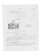
Fig 3. Equivalent electrical circuit for
piezomeasurement circuit.
Rx = Resistance of piezo
Cx = Capacitance of piezo
Cc = Capacitance of cable
Ca = Capacitance of amplifier circuit
Ra = Resistance of amplifier circuit
Another important aspect to the use of piezoelectrics is the fact that they are fabricated
using a process which relies on the crystallization of the lattice in a particular
arrangement. This is accomplished by heating the crystal to above the Curie temperature
while applying voltages to the electrodes. If the crystal is ever heated to near the Curie
temperature, it can become `de-poled' which can result in a loss of piezoelectric
sensitivity. For various materials, this Curie temperature can be as high as 600C or as low
as 50C. The need to stay below this temperature can impose serious constraints on the
applicability of these sensors.
Overall, piezoelectric elements have several important advantages over other sensing
mechanisms. First and foremost is the fact that the device generates its own voltage.
Because of this, the sensor element does not need to have power applied to it in order to
function. For applications where power consumption is a significant constraint,
piezoelectric devices can be very valuable. In addition to this, the piezoelectric effect has
some interesting scaling laws which suggest it is useful in small devices. The primary
disadvantage of piezoelectric sensing is that it is inherently sensitive only to time varying
signals. Many application require sensitivity to static quantities, and piezoelectric sensing
simply does not work for such applications.
Fig 3. Useful frequency range
Nevertheless, if you have a time-varying signal, you should give serious thought to the
use of piezoelectric sensing elements.
One recently-developed technology for piezoelectric materials involves the use of polyvinyl di-fluoride films which are treated during manufacture to have a piezoelectric
coefficient. The primary advantage of this process is that the films can be made at
extremely low cost, and they are becoming very popular for low-cost sensing
applications. One company in particular has pioneered the development of this material
AMP Inc.. In addition to the successful commercialization of a number of products based
on these piezo films, they offer unmounted film elements which are suitable for use in the
construction of simple test devices. These film elements will be the basis for Laboratory
assignment #2 of this course - Build your own Accelerometer.
Before we look at the lab in detail, lets review the properties for the film. Throughout this
review, I'll follow the descriptions given in the handout entitled : Piezo Films Technical
Manual from AMP.
(Note: The lecture continues on to a more detailed discussion of piezoelectric sensors
using the handout "Piezo Films Technical Manual from AMP". The copy of the handout
is provided for all students and therefore is not duplicated in the Web notes. Please refer
to the copy for the lecture relating to the piezo film sensors.)
Piezoelectric Accelerometer
A final example is that of a piezoelectric accelerometer. In this case, we consider an
accelerometer which consists of a 10 gm mass resting on a slab of piezoelectric material.
Assume the piezo slab has dimensions of 1 square cm in area, and 1mm thick. It is made
of PZT material with its z axis perpendicular to the large faces, which are coated with
metal contacts. What voltage is expected? where is the resonance?
The voltage is given by :
an acceleration of 1 milli-g exerts a force given by Newton's law :
which would produce a voltage of ~10^-4 V. This is measurable. As we discussed in the
piezoelectric sensor lecture, this situation can be improved in several ways. For instance,
the piezoelectric element can have a smaller area and a larger thickness.
The resonant frequency can be calculated (an exercise for the reader) and is of order 200
kHz for the above geometry. So this device can be good for applications which require
sensitivity to very high frequency vibration signals. It has the added feature that it does
not require excitation voltages. On the other hand it does require a good preamplifier.
Fig 4. Charge amplifying circuit
In any case, piezoelectric accelerometers are on the market, and are primarily offered for
vibration measurement. For moderate signals (milli-gs), fairly small devices with simple
circuits are quite sufficient, so these devices can be in the 10-100 dollar range.
Fig 5. Commercial accelerometer