Slide thiết kế vi mạch chapter1 digital design review
Bạn đang xem bản rút gọn của tài liệu. Xem và tải ngay bản đầy đủ của tài liệu tại đây (592.52 KB, 26 trang )
Digital Design with the Verilog HDL
Chapter 1: Digital Design Review
Dr. Phạm Quốc Cường
Computer Engineering – CSE – HCMUT
CuuDuongThanCong.com
/>
1
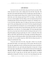
Technology Tradeoffs
Full-Custom
IC
Market Volume
to Amortize
Standard Cells
Time to Prototype
FPGAs, Gate
Arrays
PLDs
Non-Recurring Engineering (NRE) Cost
Process complexity
Density, speed, complexity
2
CuuDuongThanCong.com
/>
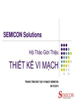
Design Methodology
Design Specification
1
5
Design Partition
2
6
3
Design Entry:
Verilog Behavioral
Modeling
4
Simulation /
Functional
Verification
7
8
Design Integration
and Verification
Pre-Synthesis
Sign-Off
Synthesize and Map
Gate-Level Netlist
Post-Synthesis
Design Validation
9
10
11
Post-Synthesis
Timing Verification
Test Generation and
Fault Simulation
Extract Parasitics
13
Design Sign-Off
14
Cell Placement, Scan
Chain and Clock Tree
Insertion, Cell Routing
Production-Ready
Masks
Verify Physical and
Electrical Design Rules
12
Verilog-based
3
CuuDuongThanCong.com
/>
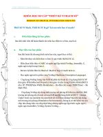
Combinational – Sequential Logic
• Combinational logic:
– The outputs at any time,
t, are a function of only
the inputs at time t
a
b
c
d
y1
Combinational
y2
Logic
y3
• Sequential logic:
– The outputs at time t are
a function of the inputs
at time t and the
outputs at time t-1
a
b
c
y1
Sequential
y2
Circuit
y3
4
CuuDuongThanCong.com
/>
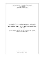
Transistor
• nMos
• pMos
5
CuuDuongThanCong.com
/>
CMOS Technology
• Complementary metaloxide semiconductor
• Outputs are always
either 0 or 1
Invert gate
pMos
Pull-up
network
Input
Output
nMos
Pull-down
network
NAND gate
NOR gate
6
CuuDuongThanCong.com
/>
Parallel and Serial
• nMOS: 1 = ON
• pMOS: 0 = ON
a
a
g1
g2
g2
b
(b)
a
0
1
1
0
1
0
1
a
b
b
b
b
OFF
OFF
OFF
ON
a
a
g1
a
0
b
(a)
a
a
a
a
0
0
1
1
0
1
0
1
• Series: all transistors
are on
• Parallel: at least one
transistor is on
g1
g2
b
(c)
b
b
b
ON
OFF
OFF
OFF
g1
g2
b
(d)
a
0 0
0
a
b
CuuDuongThanCong.com
a
a
1
a
0 1
1
1
b
b
b
b
OFF
ON
ON
ON
a
a
a
a
0 0
0
1 1
0 1
1
b
b
b
b
ON
ON
ON
OFF7
/>
The “Conduction Complement” Rule
• CMOS gate’s output is always either 0 or 1
• For example: NAND
A
Y
– Y=0 if and only if both inputs are 1
B
– Y=1 if and only at least one input is 0
– pMos transistors are parallel while nMos transistors are
serial
• The “Conduction Complements” rule
– The pull-up network always complements the pull-down
network
– Parallel → Serial, Serial → Parallel
8
CuuDuongThanCong.com
/>
CMOS Inverter
A
0
1
VDD
Y
A
A
Y
Y
GND
9
CuuDuongThanCong.com
/>
CMOS Inverter
A
0
1
VDD
Y
OFF
0
A=1
Y=0
ON
A
Y
GND
10
CuuDuongThanCong.com
/>
CMOS Inverter
A
0
1
VDD
Y
1
0
ON
A=0
Y=1
OFF
A
Y
GND
11
CuuDuongThanCong.com
/>
CMOS NAND Gate
A
0
0
1
1
B
0
1
0
1
Y
Y
A
B
12
CuuDuongThanCong.com
/>
CMOS NAND Gate
A
0
0
1
1
B
0
1
0
1
Y
1
ON
A=0
B=0
ON
Y=1
OFF
OFF
13
CuuDuongThanCong.com
/>
CMOS NAND Gate
A
0
0
1
1
B
0
1
0
1
Y
1
1
OFF
A=0
B=1
ON
Y=1
OFF
ON
14
CuuDuongThanCong.com
/>
CMOS NAND Gate
A
0
0
1
1
B
0
1
0
1
Y
1
1
1
ON
OFF
Y=1
A=1
B=0
ON
OFF
15
CuuDuongThanCong.com
/>
CMOS NAND Gate
A
0
0
1
1
B
0
1
0
1
Y
1
1
1
0
OFF
OFF
Y=0
A=1
B=1
ON
ON
16
CuuDuongThanCong.com
/>
CMOS NOR Gate
A
0
0
1
1
B
0
1
0
1
Y
1
0
0
0
A
B
Y
17
CuuDuongThanCong.com
/>
3-input NAND Gate
• Y is 0 if and only if ALL inputs are 1
• Y is 1 if and only if AT LEAST one input is 0
Y
A
B
C
18
CuuDuongThanCong.com
/>
Design CMOS Gates
• Example:
– Using the CMOS Technology, draw transistor structure of
a 4-input NOR gate
A
B
C
D
Y
19
CuuDuongThanCong.com
/>
Design CMOS Gate (cont.)
• Example 2 (Homework):
– Using the CMOS Technology, draw transistor structure of
a 4-input NAND gate
20
CuuDuongThanCong.com
/>
Compound Gates
•
Compound gates: can describe any inverter function (not
function)
21
CuuDuongThanCong.com
/>
Example: AOI22
Y = ( A • B) + (C • D)
A
C
A
C
B
D
B
D
(a)
A
(b)
B C
D
(c)
C
D
A
B
(d)
C
D
A
B
A
B
C
D
Y
A
C
B
D
Y
(f)
(e)
CuuDuongThanCong.com
22
/>
AOI22
• Use AND/OR gate to implement?
– 20 transitors
23
CuuDuongThanCong.com
/>
Example: O3AI
Y= ( A + B + C) • D
A
B
C
D
Y
D
A
B
C
24
CuuDuongThanCong.com
/>
Standard Cells
•
•
•
•
Library of common gates and structures (cells)
Decompose hardware in terms of these cells
Arrange the cells on the chip
Connect them using metal wiring
…
25
CuuDuongThanCong.com
/>