Slide thiết kế vi mạch chapter7 parameters functions task
Bạn đang xem bản rút gọn của tài liệu. Xem và tải ngay bản đầy đủ của tài liệu tại đây (1.19 MB, 38 trang )
Digital Design with the Verilog HDL
Chapter 7: Parameters, Task, and Function in
Verilog
Dr. Phạm Quốc Cường
Computer Engineering – CSE – HCMUT
CuuDuongThanCong.com
/>
1
Elaboration of Verilog Code
2
CuuDuongThanCong.com
/>
Elaboration of Verilog Code
• Elaboration is a pre-processing stage that takes place
before code is synthesized.
• It allows us to automatically alter our code before
Synthesis based on Compile-Time information
• Uses of Elaboration
–
–
–
–
–
Unrolling of FOR Loops
Parameterization
Code Generation
Constant Functions
Macros
3
CuuDuongThanCong.com
/>
Overview
• Parameters
• Generated Instantiation
• Functions and Tasks
4
CuuDuongThanCong.com
/>
Parameters
• Compile-time constant parameters in Verilog
– In Verilog: parameter N=8’d100;
– Values are substituted during Elaboration; parameters
cannot change value after synthesis
• Can be used for three main reasons
– Make code more readable
– Make it easier to update code
– Improve (re)usability of modules
5
CuuDuongThanCong.com
/>
More Readable, Less Error-Prone
parameter ADD=4’b0000;
parameter SUB=4’b0100;
parameter XOR=4’b0101;
parameter AND=4’b1010;
parameter EQ=4’b1100;
always @(*) begin
case (mode)
4’b0000: …
4’b0100: …
4’b0101: …
4’b1010: …
4’b1100: …
default: …
endcase
end
VS
always @(*) begin
case (mode)
ADD: …
SUB: …
XOR: …
AND: …
EQ: …
default: …
endcase
end
6
CuuDuongThanCong.com
/>
Reusability/Extensibility of Modules
module xor_array(y_out, a, b);
parameter SIZE = 8, DELAY = 15;
output [SIZE-1:0] y_out;
input [SIZE-1:0] a,b;
wire
#DELAY y_out = a ^ b;
endmodule
// parameter defaults
xor_array G1 (y1, a1, b1);
// use defaults
xor_array #(4, 5) G2(y2, a2, b2); // override default parameters
// SIZE = 4, DELAY = 5
• Module instantiations cannot specify delays without parameters
– Where would delays go? What type would they be?
7
CuuDuongThanCong.com
/>
Overriding Parameters
• Parameters can be overridden
– Generally done to “resize” module or change its delay
• Implicitly: override in order of appearance
– xor_array #(4, 5) G2(y2, a2, b2);
• Explicitly: name association (preferred)
– xor_array #(.SIZE(4), .DELAY(5)) G3(y2, a2, b2);
• Explicitly: defparam
– defparam G4.SIZE = 4, G4.DELAY = 15;
– xor_array G4(y2, a2, b2);
• localparam parameters in a module can’t be overridden
– localparam SIZE = 8, DELAY = 15;
8
CuuDuongThanCong.com
/>
Parameters With Instance Arrays
module array_of_xor (y, a, b);
parameter SIZE=4;
input [SIZE-1:0] a,b;
output [SIZE-1:0] y;
xor G3[SIZE-1:0] (y, a, b);
endmodule
// instantiates 4 xor gates
// (unless size overridden)
very common use of
parameters
module variable_size_register (q, data_in, clk, set, rst);
parameter BITWIDTH=8;
input [BITWIDTH-1:0] data_in;
// one per flip-flop
input clk, set, rst;
// shared signals
output [BITWIDTH-1:0] q;
// one per flip-flop
// instantiate flip-flops to form a BITWIDTH-bit register
flip_flop M [BITWIDTH-1:0] (q, data_in, clk, set, rst);
endmodule
9
CuuDuongThanCong.com
/>
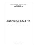
Synthesized array_of_xor
10
CuuDuongThanCong.com
/>
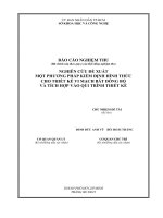
Synthesized variable_size_register
11
CuuDuongThanCong.com
/>
Parameterized Ripple Carry Adder
module RCA(sum, c_out, a, b, c_in);
parameter BITS=8;
input [BITS-1:0] a, b;
input c_in;
output [BITS-1:0] sum;
output c_out;
wire [BITS-1:1] c;
Add_full M[BITS-1:0](sum, {c_out, c[BITS-1:1]},
a, b, {c[BITS-1:1], c_in});
endmodule
Instantiate a 16-bit ripple-carry adder:
RCA #(.BITS(16)) add_16(sum, carryout, a, b,
carryin);
CuuDuongThanCong.com
/>
12
Parameterized Shift Left Register [1]
module shift(out, in, clk, rst);
parameter BITS=8;
input in, clk, rst;
output [BITS-1:0] out;
dff shiftreg[BITS-1:0](out, {out[BITS-2:0], in}, clk, rst);
endmodule
Instantiate a 5-bit shift register:
shift
#(.BITS(5)) shift_5(shiftval, shiftin, clk, rst);
13
CuuDuongThanCong.com
/>
Parameterized Shift Left Register [2]
module shift_bhv (outbit, out, in, clk, rst);
parameter WIDTH = 8;
output reg [WIDTH-1:0] out;
output reg outbit;
input in, clk, rst;
always @(posedge clk) begin
if (rst) {outbit,out} <= 0;
else {outbit,out} <= {out[WIDTH-1:0],in};
end
endmodule
Instantiate a 16-bit shift register:
shift_bhv #(16) shift_16(shiftbit, shiftout, shiftin, clk, rst);
14
CuuDuongThanCong.com
/>
Synthesized Shift Left Register
15
CuuDuongThanCong.com
/>
Parameters + Generate Statements
• Problem: Certain types of logic structures are
efficient only in certain scenarios
• For example when designing an adder:
– Ripple-Carry Adders are better for small operands
– Carry Look-ahead Adders are better for large operands
• If we change a parameter to use a larger or smaller
adder size, we may also want to change the structure
of the logic
16
CuuDuongThanCong.com
/>
Generated Instantiation
• Generate statements: control over the
instantiation/creation of
– Modules, gate primitives, continuous assignments, initial
blocks, always blocks, nets and regs
• Generate instantiations are resolved during
Elaboration
– Can alter or replace a piece of code based on compile-time
information
– Before the design is simulated or synthesized
– Think of it as having the code help write itself
17
CuuDuongThanCong.com
/>
Special Generate Variables
• Index variables used in generate statements;
declared using genvar (e.g., genvar i )
• Useful when developing parameterized modules
• Can override the parameters to create different-sized
structures
• Easier than creating different structures for all
different possible bitwidths
18
CuuDuongThanCong.com
/>
Generate-Loop
• A generate-loop permits making one or more instantiations
(pre-synthesis) using a for-loop.
module gray2bin1 (bin, gray);
parameter SIZE = 8; // this module is parameterizable
output [SIZE-1:0] bin; input [SIZE-1:0] gray;
How does this differ
genvar i;
from a standard for
generate
loop?
for (i=0; i
end
endgenerate
endmodule
19
CuuDuongThanCong.com
/>
Generate-Conditional
• A generate-conditional allows conditional (pre-synthesis)
instantiation using if-else-if constructs
module multiplier(a ,b ,product);
parameter A_WIDTH = 8, B_WIDTH = 8;
localparam PRODUCT_WIDTH = A_WIDTH+B_WIDTH;
input [A_WIDTH-1:0] a; input [B_WIDTH-1:0] b;
output [PRODUCT_WIDTH-1:0] product;
generate
if ((A_WIDTH < 8) || (B_WIDTH < 8))
CLA_multiplier #(A_WIDTH,B_WIDTH) u1(a, b, product);
else
WALLACE_multiplier #(A_WIDTH,B_WIDTH) u1(a, b, product);
endgenerate
endmodule
These are
parameters,
not variables!
22
CuuDuongThanCong.com
/>
Generate-Case
• A generate-case allows conditional (pre-synthesis)
instantiation using case constructs
module adder (output co, sum, input a, b, ci);
parameter WIDTH = 8;
generate
case (WIDTH)
1: adder_1bit x1(co, sum, a, b, ci); // 1-bit adder implementation
2: adder_2bit x1(co, sum, a, b, ci); // 2-bit adder implementation
default: adder_cla #(WIDTH) x1(co, sum, a, b, ci);
endcase
Can have a “default” in
endgenerate
a generate-case
endmodule
23
CuuDuongThanCong.com
/>
Generate a Pipeline [Part 1]
module pipeline(out, in, clk, rst);
parameter BITS = 8;
parameter STAGES = 4;
input [BITS-1:0] in;
output [BITS-1:0] out;
wire [BITS-1:0] stagein [0:STAGES-1]; // value from previous stage
reg [BITS-1:0] stage [0:STAGES-1];
// pipeline registers
assign stagein[0] = in;
generate
genvar s;
for (s = 1; s < STAGES; s = s + 1) begin : stageinput
assign stagein[s] = stage[s-1];
end
endgenerate
// continued on next slide
24
CuuDuongThanCong.com
/>
Generate a Pipeline [Part 2]
// continued from previous slide
assign out = stage[STAGES-1];
generate
genvar j;
for (j = 0; j < STAGES; j = j + 1) begin : pipe
always @(posedge clk) begin
if (rst) stage[j] <= 0;
else stage[j] <= stagein[j];
end
end
endgenerate
endmodule
What does this generate?
25
CuuDuongThanCong.com
/>
Functions and Tasks
• HDL constructs that look similar to calling a function or
procedure in an HLL.
• Designed to allow for more code reuse
• There are 3 major uses for functions/tasks
– To describe logic hardware in synthesizable modules
– To describe functional behavior in testbenches
– To compute values for parameters and other constants for
synthesizable modules before they are synthesized
• When describing hardware, you must make sure the
function or task can be synthesized!
26
CuuDuongThanCong.com
/>
Functions and Tasks in Logic Design
• It is critical to be aware of whether something you
are designing is intended for a synthesized module
– Hardware doesn’t actually “call a function”
– No instruction pointer or program counter
– This is an abstraction for the designer
• In synthesized modules, they are used to describe
the behavior we want the hardware to have
– Help make HDL code shorter and easier to read
– The synthesis tool will try to create hardware to match that
description
27
CuuDuongThanCong.com
/>