Slide thiết kế vi mạch chapter6 fsm verilog
Bạn đang xem bản rút gọn của tài liệu. Xem và tải ngay bản đầy đủ của tài liệu tại đây (1.27 MB, 18 trang )
Digital Design with the Verilog HDL
Chapter 6: FSM with Verilog
Dr. Phạm Quốc Cường
Computer Engineering – CSE – HCMUT
CuuDuongThanCong.com
/>
1
Explicit State Machines
• Declare registers to store explicit states
• Combination logic circuit controls states
• Verilog:
– Edge-trigger behaviour synchronizing the states
– Level-trigger behaviour describing the next states and
output logic
2
CuuDuongThanCong.com
/>
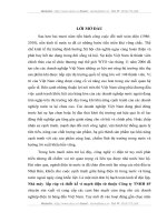
Mealy machine vs. Moore machine
Block Diagram of a Mealy sequential
machine
Block Diagram of a Moore sequential machine
3
CuuDuongThanCong.com
/>
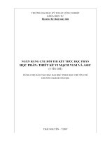
BCD to Excess-3 Converter - FSM
Next state/Output table
Next state/output
State
S_0
S_1
S_2
S_3
S_4
S_5
S_6
State transition graph
input
0
1
S_1/1
S_3/1
S_4/0
S_5/0
S_5/1
S_0/0
S_0/1
S_2/0
S_4/0
S_4/1
S_5/1
S_6/0
S_0/1
-/-
State transition table
4
CuuDuongThanCong.com
/>
BCD to Excess-3 Converter - Verilog
module BCD_to_Excess3(B_out, B_in, clk, reset);
input B_in, clk, reset;
output B_out;
parameter S_0 = 3’b000, //state encoding
S_1 = 3’b001,
S_2 = 3’b101,
S_3 = 3’b111,
S_4 = 3’b011,
S_5 = 3’b110,
S_6 = 3’b010,
dont_care_state = 3’bx,
dont_care_out = 1’bx;
reg [2:0] state, next_state;
reg B_out;
always @(posedge clk, negedge reset) //edge-trigger behaviour
if (reset == 1’b0) state <= S_0; else state <= next_state;
5
CuuDuongThanCong.com
/>
BCD to Excess-3 Converter - Verilog
always @(state, B_in) begin
B_out = 0;
case (state)
S_0:
if (B_in == 1’b0) begin
next_state = S_1;
B_out = 1’b1; end
else if (B_in == 1’b1) next_state = S_2;
S_1:
if (B_in == 1’b0) begin
next_state = S_3;
B_out = 1’b1; end
else if (B_in == 1’b1) next_state = S_4;
S_2: …
S_3: …
S_4: …
S_5: …
S_6: …
endcase
end
6
CuuDuongThanCong.com
/>
Synthesized Circuit
Phát biểu case không đủ
tất cả các trường hợp
7
CuuDuongThanCong.com
/>
BCD to Excess-3 Converter - Verilog
always @(state, B_in) begin
B_out = 0;
case (state)
S_0:
if (B_in == 1’b0) begin
next_state = S_1;
B_out = 1’b1; end
else if (B_in == 1’b0) next_state = S_2;
S_1:
if (B_in == 1’b0) begin
next_state = S_3;
B_out = 1’b1; end
else if (B_in == 1’b0) next_state = S_4;
S_2: …
S_3: …
S_4: …
S_5: …
S_6: …
default: next_state = dont_care_state;
endcase
end
8
CuuDuongThanCong.com
/>
Synthesized Circuit
9
CuuDuongThanCong.com
/>
Sequence Recognizer: Mealy
module Seq_Rec_3_1s_Mealy (output D_out, input D_in, En, clk, reset);
parameter
S_idle = 0, S_0 =
1, S_1 =
2, S_2 =
3;
reg [1: 0] state, next_state;
// Binary code
always @ (negedge clk)
Recommended Style!
if (reset == 1) state <= S_idle; else state <= next_state;
always @ (state, D_in, En) begin
case (state)
S_idle: if ((En == 1) && (D_in == 1))
next_state = S_1; else
if ((En == 1) && (D_in == 0))
next_state = S_0;
else next_state = S_idle;
S_0:
if (D_in == 0) next_state = S_0; else
if (D_in == 1) next_state = S_1; else next_state = S_idle;
S_1:
if (D_in == 0) next_state = S_0; else
if (D_in == 1) next_state = S_2; else next_state = S_idle;
S_2:
if (D_in == 0) next_state = S_0; else
if (D_in == 1) next_state = S_2; else next_state = S_idle;
default:
next_state = S_idle;
endcase
end
assign D_out = ((state == S_2) && (D_in == 1 ));
// Mealy output
endmodule
CuuDuongThanCong.com
/>
Sequence Recognizer: Mealy –
Synthesized Circuit
aoi21_a
reset_b
dffrpb_a
dffrpb_a
inv_a
clk
and2i_a
nor2_a
En
aoi211_a
inv_a
and3_a
dffrpb_a
esdpupd
D_in
CuuDuongThanCong.com
/>
D_out
Sequence Recognizer: Mealy –
Synthesized Circuit
12
CuuDuongThanCong.com
/>
Sequence Recognizer: Moore
module Seq_Rec_3_1s_Moore (output D_out, input D_in, En, clk, reset);
parameter
S_idle =
0, S_0 = 1, S_1 = 2, S_2 = 3, S_3 = 4;
reg [2: 0] state, next_state;
Prevent accidental
latches!
always @ (negedge clk)
if (reset == 1) state <= S_idle; else state <= next_state;
always @ (state or D_in) begin next_state = S_idle;
case (state)
S_idle: if ((En == 1) && (D_in == 1))
next_state = S_1;
else if ((En == 1) && (D_in == 0)) next_state = S_0;
// else next_state = S_idle; // Remove!
S_0:
if (D_in == 0) next_state = S_0;
else if (D_in == 1) next_state = S_1; // else next_state = S_idle;
S_1:
if (D_in == 0) next_state = S_0;
else if (D_in == 1) next_state = S_2; // else next_state = S_idle;
S_2, S_3:
if (D_in == 0) next_state = S_0; else if (D_in == 1) next_state = S_3;
// else next_state = S_idle;
default:
next_state = S_idle;
// Why not 3'bx?
endcase
end
assign D_out = (state == S_3);
// Moore output
endmodule
CuuDuongThanCong.com
/>
Sequence Recognizer: Moore Synthesize Circuit
and2i_a
nand2_a
mux2_a
En
reset
aoi211_a
D_in
inv_a
inv_a
dffrpb_a
inv_a
aoi211_a
inv_a
clk
nor2_a
dffrpb_a
nor2_a
dffrpb_a
esdpupd
CuuDuongThanCong.com
CSE/EE 40462 FSMs, Datapath
Controllers.14
/>
nand2_a
inv_a
D_out
Mealy machine vs. Moore machine
Block Diagram of a Mealy sequential
machine
Block Diagram of a Moore sequential machine
15
CuuDuongThanCong.com
/>
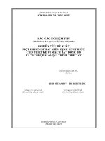
Simulation Results
Mealy
glitch
Valid output
Mealy
glitch
16
CuuDuongThanCong.com
/>
Registered Output
17
CuuDuongThanCong.com
/>
Registered Output
Mealy Type
Moore Type
18
CuuDuongThanCong.com
/>