Tài liệu Deploying IPv6 in Branch Networks docx
Bạn đang xem bản rút gọn của tài liệu. Xem và tải ngay bản đầy đủ của tài liệu tại đây (1.23 MB, 88 trang )
Corporate Headquarters:
Copyright © 2006 Cisco Systems, Inc. All rights reserved.
Cisco Systems, Inc., 170 West Tasman Drive, San Jose, CA 95134-1706 USA
Deploying IPv6 in Branch Networks
This document is intended to guide customers in their planning or deployment of IPv6 in branch
networks. This document is not meant to introduce you to branch design fundamentals and best
practices, IPv6, transition mechanisms, or IPv4 and IPv6 feature comparisons. The user must be familiar
with the Cisco branch design best practices recommendations and the basics of IPv6 and associated
transition mechanisms. For information about the enterprise design architecture, refer to the following
documents:
• Enterprise Branch Architecture Design Overview
/> • Enterprise Branch Security Design Guide
/>Contents
Introduction 3
Scope 3
Branch Deployment Overview 3
Single-Tier Profile 4
Solution Requirements 5
Tested Components 5
Dual-Tier Profile 6
Solution Requirements 7
Tested Components 7
Multi-Tier Profile 7
Solution Requirements 8
Tested Components 8
General Considerations 8
Addressing 9
2
Deploying IPv6 in Branch Networks
OL-11819-01
Contents
Physical Connectivity 9
VLANs 10
Routing 10
High Availability 11
QoS 11
Security 12
Multicast 14
Management 15
Scalability and Performance 16
Single-Tier Implementation 18
Network Topology 18
WAN Configuration 19
LAN Configuration 20
IPSec and Manual Tunnel Configuration 21
Routing 23
Security 25
QoS 28
Multicast 31
Dual-Tier Implementation 32
Network Topology 33
WAN Configuration 34
LAN Configuration 34
Routing 37
Security 39
QoS 41
Multicast 42
Conclusion 42
Future Work 42
References 43
Recommended Reading 43
Cisco-Specific Links 43
Microsoft IPv6 Links 44
IPv6 Industry Links 44
Enterprise Design Architecture Reference 45
Configuration Examples 45
Single-Tier Profile 45
2800-br1-1 45
7206 VPN Configurations for Single-Tier Profile 63
7206-1 63
3
Deploying IPv6 in Branch Networks
OL-11819-01
Introduction
7206-2 65
Dual-Tier Profile 66
2800-br2-1 66
2800-br2-2 74
3560-br2-1 82
Introduction
This document requires a basic understanding of Cisco branch design. This prerequisite knowledge can
be acquired through many documents and training opportunities that are available through Cisco
Systems, Inc. and through the networking industry at large.
Recommended Reading, page 43 contains
resources for these areas of interest.
Scope
This document provides a brief overview of the various branch IPv6 deployment profiles and general
deployment considerations. This document also covers the implementation details for each branch
profile individually.
In addition to configurations shown in the general considerations and implementation sections, the full
configurations for each branch device can be found in
Configuration Examples, page 45. This document
focuses on the branch-side of the WAN, but the basic configurations used on the HQ WAN routers are
shown, for reference, in
Configuration Examples, page 45. These configurations were used for testing
only and are not necessarily the recommended WAN router configurations the customer should use. A
future document that covers IPv6 deployments in the enterprise WAN edge is planned. Updates to this
document and new IPv6-related documents can be found at
/>Branch Deployment Overview
This section provides a high-level overview of the two mostly commonly deployed Cisco branch profiles
to provide a basic understanding of how IPv6 can be integrated into these two branch profiles.
The branch IPv6 deployment profiles that are described in this section:
• Single-Tier Profile, page 4
• Dual-Tier Profile, page 6
• Multi-Tier Profile, page 7
Note Only a high-level overview is provided for the multi-tier profile in this section; it is not discussed in the
general considerations or implementation sections of this document. The IPv6 component of the
multi-tier profile will be tested and documented in future branch design guides.
4
Deploying IPv6 in Branch Networks
OL-11819-01
Branch Deployment Overview
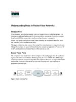
Single-Tier Profile
The single-tier branch profile is a fully integrated solution. The requirements for LAN and WAN
connectivity and security are met by a single Integrated Services Router (ISR).
Figure 1 shows a
high-level view of the single-tier branch profile.
Figure 1 Single-Tier Profile
In the single-tier profile described in this document, a single ISR is used to provide WAN connectivity
via a T1 to an Internet Service Provider (ISP). This T1 is used as the primary link to the headquarters
(HQ) site. For WAN redundancy, a backup connection is made via Asymmetric Digital Subscriber Line
(ADSL). The single-tier uses what is often referred to as the “Internet Deployment Model.”
IPv4 connectivity to the HQ site is provided by IPv4 IPSec using Dynamic Multi-Point Virtual Private
Network (DMVPN) technologies. IPv6 connectivity to the HQ site is provided by using manually
configured tunnels (IPv6-in-IPv4) that are protected by IPv4 IPSec. The DMVPN and manually
configured tunnels traverse the T1 link as the primary path and establish backup tunnels over the ADSL
link. In the single-tier profile described in this document, IPv6 connectivity via the IPSec-protected
manually configured tunnels is required because DMVPN does not yet support IPv6. When DMVPN
supports IPv6 within the design, then no additional tunnel configurations are required and IPv4/IPv6
(dual-stack) is supported within the same DMVPN design.
All traffic leaving the branch traverses the VPN connections to the HQ, including the Internet bound
traffic. Generally, Cisco does not recommend the use of split-tunneling at the branch site. If the customer
requires split-tunneling, then Cisco recommends a careful analysis and testing of the routing and the
security implications of such a deployment.
Note While it not covered in this document, it is also possible to establish native IPv6 IPSec tunnels from the
ISR to the HQ site if the ISPs offers IPv6 support to the branch and HQ sites. In this document it is
assumed that no IPv6 services are offered from the ISP to the branch site. More information on IPv6
IPSec configurations and support can be found at
LAN connectivity is provided by an integrated switch module (EtherSwitch Service Module). Dual-stack
(running both IPv4 TCP/IP stack and IPv6 TCP/IP stack) is used on the VLAN interfaces at the branch.
220152
Dual-Stack Host
(IPv6/IPv4)
T1
Single-Tier
ADSL
IPv4
IPv6
Internet
Headquarters
Branch
Primary DMVPN Tunnel (IPv4)
Secondary DMVPN Tunnel (IPv4)
Primary IPSec-protected Configured Tunnel (IPv6-in-IPv4)
Secondary IPSec-protected Configured Tunnel (IPv6-in-IPv4)
5
Deploying IPv6 in Branch Networks
OL-11819-01
Branch Deployment Overview
In addition to all of the security policies in place at the HQ, local security for both IPv4 and IPv6 is
provided by a common set of infrastructure security features and configurations in addition to the use of
the Cisco IOS Firewall. QoS for IPv4 and IPv6 is integrated into a single policy.
The obvious disadvantage of the single-tier profile is the lack of router and switch redundancy. There is
redundancy for the link to the Internet and the VPN connections to HQ. However, because there is a
single integrated switch and single router, if either component fails then the site is completely
disconnected from HQ. The dual-tier profile is the solution for customers requiring complete redundancy
for all components (switches, routers, and HQ connections).
Solution Requirements
The solution requirements for the single-tier profile are:
• IPv6 support on the Operating System (OS) of the host machines in the branch
• IPv6/IPv4 dual-stack support on the Cisco ISR router
• MLD-snooping support on the LAN switch - Integrated Network module (required if using IPv6
multicast)
• Manually configured tunnel (IPv6-in-IPv4) support on the Cisco ISR router
• Cisco IOS release and feature set that supports the Cisco IOS Firewall
• Cisco IOS release and feature set that supports IPSec and DMVPN
Tested Components
Table 1 lists the components that were used and tested in the single-tier profile.
Ta b l e 1 Single Tier Profile Components
Role Hardware Software
Router/firewall Integrated Services router: 2800 Series
and 3800 Series
Advanced Enterprise Services
12.4.(6)T2
Switch EtherSwitch Service Module–
NME-X-23ES-1G-P
Advanced IP Services 12.2(25)SEE
Host devices Various laptops: IBM, HP, and Apple Microsoft Windows XP SP2, Vista
RC1, Apple Mac OS X 10.4.7, and
Red Hat Enterprise Linux WS
6
Deploying IPv6 in Branch Networks
OL-11819-01
Branch Deployment Overview
Dual-Tier Profile
The dual-tier profile separates the routing and switching roles in the branch. Figure 2 shows a high-level
view of the dual-tier profile.
Figure 2 Dual-Tier Profile
There are three primary differences between the single-tier and dual-tier profile:
• Redundancy
• Scalability
• WAN transport
Redundancy—The dual-tier separates the LAN (switch) and WAN (router) components to offer
fault-tolerance. A single switch or multiple switches can be used to provide LAN access in the branch.
There are two WAN routers that are redundantly connected to the Frame Relay cloud, in addition to being
redundantly connected to the LAN switch.
Scalability—The dual-tier scales better because the single-tier is pretty much an “everything but the
kitchen sink” approach. In other words, every network role required in the branch is performed by the
ISR. This is great for cost and manageability, but can limit availability and scalability. The larger the
branch and the more services enabled on the ISR, the higher the risk gets for over-extending the
performance capabilities of the ISR. This can be alleviated by using a more powerful ISR model, but this
does not help with the fault-tolerance requirement. If additional LAN switches are needed at the branch
then the Catalyst switches can be used together using the Cisco StackWise topology.
WAN Transport —The WAN connections in the dual-tier model described in this document use Frame
Relay instead of the Internet with IPSec VPN. IPv6 is fully supported over Frame Relay in Cisco IOS
and therefore there is no need to run tunnels of any kind between the branch and HQ. This is a great
advantage for deployment and management because dual-stack is used all the way from the hosts in the
branch LAN across the WAN and into the HQ network. This greatly eases the operational aspects of
deploying IPv6 in the branch because no special tunnel considerations (such as availability, security,
QoS, and multicast) need to be made. The dual-tier uses what is often referred to as the “private WAN
model.”
Security for the dual-tier is the same as the single-tier with the exception that both routers in the dual-tier
provide security services and that no IPSec tunnels are used. The majority of branch deployments today
use the dual-tier profile.
220153
Dual-Stack Host
(IPv6/IPv4)
Dual-Tier
IPv4
IPv6
Frame
Relay
Headquarters
Branch
7
Deploying IPv6 in Branch Networks
OL-11819-01
Branch Deployment Overview
Solution Requirements
The solution requirements for the dual-tier profile are:
• IPv6 support on the Operating System (OS) of the host machines in the branch
• IPv6/IPv4 dual-stack support on the Cisco ISR routers
• MLD-snooping support on the LAN switches (required if using IPv6 multicast)
Tested Components
The components that were used and tested in the dual-tier profile are listed in Table 2.
Multi-Tier Profile
As previously mentioned, the multi-tier profile is covered only at a high-level and is not covered in the
implementation section. Future work is planned for testing and documenting IPv6 in the multi-tier
profile. It is described here for completeness and to prompt you to think about some of the design aspects
of IPv6 in a multi-tier type deployment.
Figure 3 shows a high-level view of the multi-tier profile.
Figure 3 Multi-Tier Profile
Ta b l e 2 Dual Tier Profile Components
Role Hardware Software
Router Integrated Services router: 2800 Series
and 3800 Series
Advanced Enterprise Services
12.4.(6)T2
Switch Catalyst 3750 Advanced IP Services 12.2(25)SEE
Host devices Various laptops: IBM, HP, and Apple Microsoft Windows XP SP2, Vista
RC1, Apple Mac OS X 10.4.7, and Red
Hat Enterprise Linux WS
220154
Dual-Stack Host
(IPv6/IPv4)
Multi-Tier
IPv4
IPv6
MPLS
Headquarters
Branch
LAN
Tier
Access
Tier
WAN
Tier
Firewall
Tier
8
Deploying IPv6 in Branch Networks
OL-11819-01
General Considerations
Figure 3 shows how the tiers or roles are distributed. Several changes are evident with the multi-tier vs.
the dual-tier:
• WAN Tier—Connections to HQ are now over MPLS vs. Frame Relay. This is not required, but
shown as an alternative.
• Firewall Tier—Firewall services are now separated from the WAN routers. The Cisco ASA 5500
series is shown here and is providing stateful firewall services for both IPv4 and IPv6. The second
ASA (shown in the figure as (subdued) grey) is in stateful failover mode. In a stateful failover
configuration, only one ASA is active at a time.
• Access Tier—The access tier is used for internal service and VLAN termination for the LAN tier.
The access tier is like a campus distribution layer in many ways.
• LAN Tier—The LAN tier is the same as with the dual-tier LAN switch. There are just more of them
to account for the larger scale requirements that are most likely found in a larger branch.
Solution Requirements
The solution requirements for the multi-tier profile are:
• IPv6 support on the Operating System (OS) of the host machines in the branch
• IPv6/IPv4 dual-stack support on the Cisco ISR routers
• MLD-snooping support on the LAN switches (required if using IPv6 multicast)
• Cisco ASA Software version 7.0 and later
Tested Components
Testing and documentation is planned for IPv6 in a multi-tier profile. For updates, periodically refer to
/>General Considerations
There are some general considerations that apply to both deployment profiles described in the
implementation sections of this document. This section describes the general considerations to take into
account when deploying IPv6 in a branch network, regardless of the deployment profile being used. If a
specific consideration should be understood, then the specific profile is called out, along with the
consideration for that profile. Also, the specific configurations for any profile-specific considerations
can be found in that profile's implementation section.
Both branch IPv6 profiles described in this document leverage the existing Cisco branch network design
best practices as the foundation for all aspects of the deployment. The IPv6 components of the profiles
are deployed in the same way as IPv4 whenever possible. When the same or similar features are not
available for IPv6 as for IPv4, alternatives are used. In some cases, no alternatives are available and a
reference for where to track feature support is given.
It is critical to understand the Cisco branch best practices recommendations before deploying the IPv6
in the branch profiles described in this document. The Cisco branch design best practice documents can
be found under the “Branch Office” and “WAN” sections at
Note The applicable commands in each section below are in red text.
9
Deploying IPv6 in Branch Networks
OL-11819-01
General Considerations
Addressing
As previously mentioned, this document is not an introductory document and does not describe the
basics of IPv6 addressing. However, it is important to describe a few addressing considerations for the
network devices.
In most cases, the use of a /64 prefix on point-to-point (P2P) links is just fine. IPv6 was designed to have
a large address space and even with the poor address management in place, the customer should not
experience address constraints.
Some network administrators think that a /64 prefix for P2P links is a waste of time. There has been quite
a bit of discussion within the IPv6 community about the practice of using longer prefixes for P2P links.
For those network administrators who want to more tightly control the address space, then it is safe to
use a /126 prefix on P2P links in much the same was as /30 is used with IPv4.
RFC 3627 describes the reasons why the use of a /127 prefix is harmful and should be discouraged. For
more information, refer to
/>In general, Cisco recommends using either a /64 or /126 on P2P links. There are efforts underway within
the IETF to better document the address assignment guidelines for varying address types and prefix
links. IETF work within the IPv6 operations working group can be tracked at
/>The P2P configurations shown in this document use /64 prefixes. The assignment of user IPv6 addresses
in the single and dual-tier profiles is done by advertising an IPv6 prefix (via an RA) on the router
sub-interface for the VLAN where PCs are located. The options for DNS server and domain name are
assigned using DHCP for IPv6. All other VLANs use stateless autoconfiguration alone with no use of
options. More information can be found on IPv6 addressing services at the following URLs:
• Cisco IOS DHCP for IPv6:
/> • Cisco IOS IPv6 Addressing:
Physical Connectivity
Considerations for physical connectivity with IPv6 are the same as with IPv4 plus three additional
elements:
• One important factor for deployment of any new technology, protocol, or application is to ensure
that there is a sufficient amount of bandwidth for both existing and new traffic. This issue is
especially true with the branch because in many cases the connections to the WAN are low-speed
links and the reliance on QoS to solve bandwidth problems goes only so far. Bandwidth
requirements for IPv6 are outside the scope of this document because there are many variables to
account for and should therefore be considered in a case-by-case analysis.
• Understanding how IPv6 deals with Maximum Transmission Unit (MTU) on a link. This document
is not meant to be an introductory document for basic IPv6 protocol operation or specifications, so
Cisco recommends that you refer to the following links for more information on MTU and
fragmentation in IPv6. A good starting point for understanding MTU and Path MTU Discovery
(PMTUD) for IPv6 is with RFC 2460 and RFC 1981 at
10
Deploying IPv6 in Branch Networks
OL-11819-01
General Considerations
Another aspect of MTU relates to the branch single-tier profile. When IPSec is used with GRE or
manual tunnels it is important to account for how to adjust the MTU value on the routers to ensure
that the router is not forced to perform fragmentation of the IPv4 traffic due to the IPSec header and
the additional tunnel overhead. More information on this can be found in any of the IPSec design
guides at
_list.html#anchor9.
• IPv6 over Wireless LANs—IPv6 should operate correctly over WLAN Access Points in much the
same way as IPv6 operates over Layer-2 switches. However, there are considerations to IPv6 with
WLAN environments such as managing WLAN devices (APs and controllers) via IPv6 and
controlling IPv6 traffic via AP or controller-based QoS, VLANs and ACLs. IPv6 must be supported
on the AP and/or controller devices in order to take advantage of these more intelligent services on
the WLAN devices.
It is important to point out that Cisco supports the use of IPv6-enabled hosts that are directly attached
to Cisco IP phones ports. These IP phone ports are switch ports and operate in much the same way as
plugging the host directly into a Catalyst Layer 2 switch.
In addition to the previous considerations, Cisco recommends that a thorough analysis of the existing
traffic profiles, memory and CPU use on both the hosts and network equipment and also the Service
Level Agreement (SLA) language be completed prior to implementing any of the IPv6 models described
in this document.
VLANs
VLAN considerations for IPv6 are the same as for IPv4. When dual-stack configurations are used then
both IPv4 and IPv6 traverse the same VLAN. The use of Private VLANs is not included in any of the
deployment profiles described in this document and it was not tested. The use of Private VLANs will be
included in future IPv6 documents.
The use of IPv6 on data VLANs that are trunked along with Voice VLANs (behind IP phones) is fully
supported. For the current VLAN design recommendations, refer to the Cisco branch-LAN design best
practice documents at
_guidances_list.html#anchor1.
Routing
Choosing an IGP to run in the campus network is based on a variety of factors; platform capabilities, IT
staff expertise and the size of network are just a few. In this document the IGP for both IPv4 and IPv6 is
EIGRP. OSPFv2 for IPv4 and OSPFv3 for IPv6 can be used also.
As previously mentioned, every effort to implement the current Cisco branch design best practices has
been made. Both the IPv4 and IPv6 IGPs have been tuned according to the current best practices for the
branch. It should be one of the top priorities of any network design to ensure that the IGPs are tuned to
provide a stable, scalable and fast converging routing protocol.
The implementation sections show the EIGRP tuning in accordance with the current Cisco branch
recommendations.
EIGRP has been configured to provide authentication for both IPv4 and IPv6 adjacencies and updates.
11
Deploying IPv6 in Branch Networks
OL-11819-01
General Considerations
High Availability
There are many aspects of High-Availability (HA) that are not applicable to or are outside the scope of
this document. Many of the HA requirements and recommendations are met by leveraging the existing
Cisco branch design best practices. The primary HA components described in this document are:
• Redundant WAN connections—In the single-tier profile, the primary WAN connection is a T1 to the
ISP and the secondary is an ADSL connection to another ISP. However, both of these links come
from only one ISR router (branch router). In the dual-tier profile, each of the two branch ISR routers
has a Frame Relay connection to the Private WAN.
• Redundant routing and forwarding paths—This is accomplished by leveraging EIGRP for IPv4 and
IPv6. In some cases, Equal Cost Multi-Path (ECMP) is used and in other cases (IPSec GRE and
manual tunnels), one path is preferred over another, but the secondary path is available for
redundancy.
• High-availability of the first-hop gateways—This level of HA applies only to the dual-tier profile
(single-tier has only one router). HSRPv2 for IPv4 and IPv6 is used to provide first-hop gateway
redundancy in the dual-tier. Cisco also supports GLBP for IPv4 and IPv6.
QoS
Cisco recommends that QoS policies be implemented application or service-dependent instead of
protocol (IPv4 or IPv6) dependent. Basically, if the existing QoS policy has specific classification,
policing, and queuing for an application then that policy should treat the IPv4 and IPv6 traffic for that
application equally.
The key consideration as far as Modular QoS CLI (MQC) is concerned is the removal of the ip keyword
in the QoS match and set statements when IPv6 QoS is required. Modification in the QoS syntax to
support IPv6 and IPv4 allows for a new configuration criteria (see
Table 3).
There are QoS features that work for both IPv6 and IPv4, and require no modification to the CLI (such
as WRED, policing, and WRR).
The implementation section for each profile does not go into great detail on QoS configuration as far as
the definition of classes for certain applications, the associated mapping of DSCP values, and the
bandwidth and queuing recommendations. The section,
Configuration Examples, page 45 contains the
full configurations for IPv4 and IPv6 QoS used in the single and dual-tier profiles.
Cisco has an extensive collection of QoS recommendations for the branch and you are encouraged to
seek guidance from the CCO documentation and also the Cisco Press book “End-to-End QoS Network
Design.” Refer to
Recommended Reading, page 43 to find out more about Cisco branch QoS
recommendations and Cisco Press books.
Ta b l e 3 Qos Syntax Modifications
IPv4-Only QoS Syntax IPv4/IPv6 QoS Syntax
match ip dscp match dscp
match ip precedence match precedence
set ip dscp set dscp
set ip precedence set precedence
12
Deploying IPv6 in Branch Networks
OL-11819-01
General Considerations
Security
Many of the common threats and attacks on existing IPv4 campus networks also apply to IPv6.
Unauthorized access, spoofing, routing attacks, viruses, worms, DoS, and man-in-the-middle attacks are
just a few that plague both IPv4 and IPv6.
There are many new threats with IPv6 that do not exist with IPv4 or they operate differently from IPv4.
There are inherent differences in how IPv6 handles neighbor and router advertisement and discovery,
headers, and even fragmentation. Based on all of these variables and possibilities, IPv6 security is a very
involved topic in general and detailed security recommendations and configurations are outside the
scope of this document. There are numerous efforts both within Cisco and the industry to identify,
understand, and resolve IPv6 security threats. This document points out some possible areas to address
within the branch and gives basic examples of how to provide protection of IPv6 dual-stack and tunneled
traffic.
Note The examples given in this document are not meant to be recommendations or guidelines, but rather
points to stimulate a careful analysis of existent security policies and their extension to cover IPv6 in the
campus.
General security considerations for network device protection that apply to both branch profiles are as
follows:
• Make reconnaissance more difficult through proper address planning for campus switches:
–
Addressing of branch network devices (switches and router) should be well thought out and
planned. Common recommendations are to devise an addressing plan so that the 64-bit
interface-ID of the router is a value that is random across all of the devices. An example of a
bad interface-ID for a device would be if VLAN 2 had an address of 2001:db8:cafe:2::1/64 and
VLAN 3 had an address of 2001:db8:cafe:3::1/64 where ::1 is the interface-ID of the router.
This is easily guessed and allows for an attacker to quickly understand the common addressing
for the branch infrastructure devices. A better choice would be to randomize the interface-ID of
all of the network devices in the branch. Using the previous VLAN 2 and VLAN 3 examples, a
new address can be constructed by using an address like 2001:db8:cafe:2::a010:f1a1 for VLAN
2 and 2001:db8:cafe:3::c801:167a for VLAN 3 where “a010:f1a1” is the interface-ID of VLAN
2 for the router.
The addressing consideration described here introduces real operational challenges. For the
sake of easing operational management of the network devices and addressing, you should
balance the security aspects of randomizing the interface-IDs with the ability to deploy and
manage the devices via the randomized addresses.
• Controlling management access to the branch routers and switches:
–
All of the branch routers and switches for each profile have configurations in place to provide
management access protection to the devices. All routers have loopback interfaces configured
for management and routing purposes. The IPv6 address for the loopback interfaces uses the
previously mentioned addressing approach of avoiding well-known interface-ID values. In this
example the interface-ID is using “::bad1:a001.”
interface Loopback0
ipv6 address 2001:DB8:CAFE:1000::BAD1:A001/128
no ipv6 redirects
To more tightly restrict access to a particular switch/router via IPv6, an ACL is used to permit
access to the management interface (line vty) by way of the loopback interface. The permitted
source network is from the enterprise IPv6 prefix. To make ACL generation more scalable for
13
Deploying IPv6 in Branch Networks
OL-11819-01
General Considerations
a wide range of network devices, the ACL definition can permit the entire enterprise prefix as
the primary method for controlling management access to the device instead of filtering to a
specific interface on the device. The IPv6 prefix used in this enterprise site (for example only)
is 2001:db8:cafe::/48.
ipv6 access-list MGMT-IN
remark Permit MGMT only to Loopback0
permit tcp 2001:DB8:CAFE::/48 host 2001:DB8:CAFE:1000::BAD1:A001
deny ipv6 any any log-input
!
line vty 0 4
session-timeout 3
access-class MGMT-IN-v4 in
password 7 08334D400E1C17
ipv6 access-class MGMT-IN in #Apply IPv6 ACL to restrict access
logging synchronous
login local
exec prompt timestamp
transport input ssh #Accept access to VTY via SSH
–
Controlling access via HTTP—At the time of writing this document, Cisco IOS does not
support the use of IPv6 HTTP ACLs to control access to the device. This is very important
because switches and routers that currently use “ip http access-class” ACLs for IPv4 do not have
the same level of protection for IPv6. This means that subnets or users who were previously
denied access via HTTP/HTTPS for IPv4 now have access to the switch or router via IPv6.
• Control Plane Policing (CoPP)—CoPP protects the router by preventing DoS or unnecessary traffic
from negatively impacting CPU resources. Priority is given to important control plane/management
traffic. The configuration of CoPP is based on a wide variety of factors and no single deployment
recommendation can be made as the specifics of the policy are determined on a case-by-case basis.
More information on CoPP can be found at
/products_configuration_guide_chapter09186a00804559b7.html.
• Controlling ingress traffic from the branch LAN—Filter which prefixes are allowed to source traffic.
This is most commonly done on ingress on the LAN or sub-interface on the branch router.
Controlling IPv6 traffic based on source prefix can help protect the network against basic spoofing.
The following example shows a basic ACL for the dual-tier profile - applied ingress on a branch
router's LAN interface:
ipv6 access-list DATA_LAN-v6
remark PERMIT ICMPv6 PACKETS FROM HOSTS WITH PREFIX 2001:DB8:CAFE:2100::/64
permit icmp 2001:DB8:CAFE:2100::/64 any
remark PERMIT IPv6 PACKETS FROM HOSTS WITH PREFIX 2001:DB8:CAFE:2100::64
permit ipv6 2001:DB8:CAFE:2100::/64 any
remark PERMIT ALL ICMPv6 PACKETS SOURCED BY HOSTS USING THE LINK-LOCAL PREFIX
permit icmp FE80::/10 any
remark PERMIT HSRPv2 FOR IPv6 FROM OTHER BRANCH ROUTER ON LAN SEGMENT
permit udp any any eq 2029
remark PERMIT DHCPv6 ALL-DHCP-AGENTS REQUESTS FROM HOSTS
permit udp any eq 546 any eq 547
remark PERMIT ALL PIM (103) MESSAGES FROM OTHER BRANCH ROUTER ON LAN SEGMENT
permit 103 FE80::/10 any
remark DENY ALL OTHER IPv6 PACKETS AND LOG
deny ipv6 any any log-input
!
interface FastEthernet0/0.100
description DATA VLAN for PCs
ipv6 traffic-filter DATA_LAN-v6 in
14
Deploying IPv6 in Branch Networks
OL-11819-01
General Considerations
Caution Cisco IOS IPv6 ACLs contain implicit permit entries for IPv6 neighbor discovery. If deny ipv6 any any
is configured, then the implicit neighbor discovery entries are overridden. It is important that if a
manually configured catch-all deny statement is used for logging purposes then the following two permit
entries must be added back in: permit icmp any any nd-na and permit icmp any any nd-ns.
In the previous DATA_LAN-v6 example, a more permissive entry (permit icmp FE80::/16 any) is made
to account for the neighbor discovery requirement and any other ICMPv6 services that are needed on the
interface. This is a wide-open ACL entry that is permitting all ICMPv6 traffic, which is probably not a
great idea because there are many known and unknown ICMPv6-based threats that need to be
considered. There are RFCs, drafts, and IPv6 deployment books that specifically describe the various
ICMPv6 types that should and should not be blocked. Refer to
Recommended Reading, page 43 for links
to the IETF and Cisco Press book that describes the filtering of ICMPv6 packets.
• IPv6 Stateful Firewall Services—Firewalls provide a stateful security inspection for IPv6 traffic
entering or leaving a branch network. At the time of writing this document, the Cisco IOS Firewall
for IPv6 has fewer features than that of IPv4. Specifically, Advanced Application Inspection and
Control does not yet support IPv6.
• Blocking the use of Microsoft Teredo—Teredo is used to provide IPv6 support to hosts that are
located behind Network Address Translation (NAT) gateways. Teredo introduces several security
issues that need to be thoroughly understood. Until well-defined security recommendations can be
made for Teredo in branch networks, you might want to ensure that Teredo is disabled on Microsoft
Windows XP SP2 and that Vista is configured to disable Teredo at the branch. As a backup
precaution, you might want to consider configuring ACLs (this can be done at the branch router or
further upstream, such as at the border routers) to block UDP port 3544 in order to prevent Teredo
from establishing a tunnel outside of the enterprise network. Information on Teredo can be found at
/prodtechnol/winxppro/maintain/teredo.mspx.
• Disabling unused services—Many services, such as HTTP server, are supported for IPv4 and IPv6.
Enabling or disabling these services generally applies to both protocols. Refer to
References,
page 43 for the most common router and switch services that should be disabled.
More information on IPv6 security can be found in References, page 43. Also, IPv6 ACL and firewall
configuration details can be found at
/software/ios123/123cgcr/ipv6_c/v6_tffw.htm.
Multicast
IPv6 multicast is an important service for any enterprise network design. One of the most important
factors to IPv6 multicast deployment is to ensure that host/group control is handled properly in the
branch LAN. Multicast Listener Discovery (MLD) in IPv6 is the equivalent to Internet Group
Management Protocol (IGMP) in IPv4. Both are used for host multicast group membership control.
MLD-snooping is the ability to control the distribution of multicast traffic only to the ports that have
listeners. Without it, multicast traffic meant for only a single receiver (or group of receivers) would be
flooded to all ports on the branch LAN switch belonging to the same VLAN. In the branch LAN it is
important that the switches support MLD-snooping for MLD version 1 and/or version 2.
15
Deploying IPv6 in Branch Networks
OL-11819-01
General Considerations
Note At the time of writing this document, there were very few host implementations of MLDv2. Various
Linux and BSD implementations support MLDv2 as does Microsoft Windows Vista. MLDv2 is
important in PIM-SSM-based deployments. The use of MLDv2 with PIM-SSM is an excellent design
combination for a wide variety of IPv6 multicast deployments.
Today, Cisco IOS supports the following PIM implementations: PIM-SM, PIM-BSR, PIM-SSM,
Bidirectional PIM, Embedded-RP, and Multiprotocol BGP for the IPv6 Multicast Address Family.
In this document, IPv6 multicast-enabled applications are supported in both branch profiles. The
multicast-enabled applications tested in this design are: Windows Media Services and VLC (VideoLAN
Media client) using Embedded-RP and PIM-SSM groups. The multicast sources are running on
Microsoft Windows Server 2003, Longhorn and Red Hat 4.0 servers located in the HQ data center.
There are several documents on CCO and within the industry that describe IPv6 multicast in detail. Other
than generic references to the commands that are used to enable IPv6 multicast and requirements for
Embedded-RP definition, no other configuration notes are made in this document. For more information,
refer to the following URLs:
• Cisco IPv6 Multicast web page:
• Cisco IOS IPv6 Multicast Configuration:
_mcast.htm#wp1133942
Management
Management for IPv6 is under development and has a long way to go. Many of the traditional
management tools used today also support IPv6. In this document the only considerations for
management of the branch network are related to basic control of management services (Telnet, SSH,
and SNMP). All of the IPv6-enabled devices in the two branch profiles described are manageable over
IPv6 via the previously mentioned services except SNMP. At the time of writing this document, the
Catalyst switches described (Integrated switch module and 3750) do not yet support SNMP over IPv6
transport. However, the management of IPv6-specific MIBs/Traps/Informs is supported on the Catalyst
platforms using SNMP transport over IPv4. All Cisco ISRs support SNMP over IPv6 transport.
The deployment of SNMP for IPv6 is the same as with IPv4. In the branch profiles described in this paper
SNMPv3 (AuthNoPriv) is used to provide polling capabilities for the Cisco NMS servers located in the
HQ data center. Here is an example of the SNMPv3 configuration used in the branch routers in this
document:
snmp-server contact John Doe -
snmp-server group IPv6-ADMIN v3 auth write v1default
snmp-server user jdoe IPv6-ADMIN v3 auth md5 cisco1234
If information needs to be sent to a Cisco NMS server then an SNMP host can be defined. The host can
be defined to send SNMP information over IPv4 and/or IPv6:
snmp-server host 2001:DB8:CAFE:11:2E0:81FF:FE2C:9332 version 3 auth jdoe
16
Deploying IPv6 in Branch Networks
OL-11819-01
General Considerations
Another area of management that you must thoroughly research is that of address management. Anyone
who analyzed IPv6 even at an elementary level understands the size and potential complexity of
deploying and managing the IPv6 address space. The process of assigning large hexadecimal addresses
to many network devices should, at some point, be automated or at least made more user-friendly than
it is today. There are several efforts underway within the industry to provide recommendations and
solutions to the address management issues. Cisco is in the forefront of this effort.
Today, one way to help with the deployment of address prefixes on a Cisco ISR is through the use of the
general prefix feature. The general prefix feature allows the customer to define a prefix or prefixes in the
global configuration of the router with a user-friendly name. That user-friendly name can be used on a
per-interface basis to replace the usual IPv6 prefix definition on the interface. Following is an example
of how to use the general prefix feature:
Define the general prefix:
2801-br1-1(config)# ipv6 general-prefix ESE-BR-1 2001:DB8:CAFE::/48
Configure the general prefix named “ESE-BR-1” on a per-interface basis:
2801-br1-1(config-if)# ipv6 address ESE-BR-1 ::1100:0:0:BAD1:A001/64
Verify that the general prefix was correctly assigned to the interface:
2801-br1-1# show ipv6 interface g1/0.100
GigabitEthernet1/0.100 is up, line protocol is up
IPv6 is enabled, link-local address is FE80::217:94FF:FE90:2829
No Virtual link-local address(es):
Description: DATA VLAN for Computers
Global unicast address(es):
2001:DB8:CAFE:1100::BAD1:A001, subnet is 2001:DB8:CAFE:1100::/64
More information on the general prefix feature can be found at the Cisco IOS IPv6 documentation page
at
_c/v6addres.htm#wp1132473.
Cisco supports the management of IPv6-enabled network devices via a variety of Network Management
Products to include DNS, DHCPv6, device management and monitoring and also network management,
troubleshooting and reporting. More information on the various Cisco Network Management solutions
can be found at
Scalability and Performance
This document is not meant to analyze scalability and performance information for the various platforms
tested. The coverage of scale and performance is more focused on general considerations when planning
and deploying IPv6 in the branch vs. a platform-specific view.
In general, you should understand the link, memory, and CPU use of the existing branch network
devices. If any of these aspects are already stressed then adding IPv6 or any new technology, feature or
protocol into the design is a recipe for disaster.
Scalability and Performance considerations for the branch network devices:
• It is common to see in IPv6 implementations a change in traffic utilization ratios on the branch
network links. As IPv6 is deployed, IPv4 traffic utilization is very often reduced as users leverage
IPv6 as the transport for applications that were historically IPv4-only. There is often a slight
increase in overall network utilization which usually derives from control traffic for routing and also
tunnel overhead (single-tier) when manually configured tunnels are used.
17
Deploying IPv6 in Branch Networks
OL-11819-01
General Considerations
• ARP/Neighbor cache: One of the primary scalability considerations is that of running two protocols
on the router. The branch LAN router has to track both IPv4 and IPv6 neighbor information. Similar
to ARP in IPv4, neighbor cache exists for IPv6. The primary consideration here is that with IPv4
there is usually a 1-to-1 mapping of IPv4 address-to-MAC address, but with IPv6 the host can have
several mappings for multiple IPv6 addresses, such as link-local, unique-local, and multiple Global
addresses), to a single MAC address in the routers neighbor cache. Following is an example of ARP
and neighbor cache entries on a Cisco ISR located in the branch for a host with the MAC address of
“0014.c2e1.e679.”
ARP entry for the host in the branch:
Internet 10.124.2.4 2 0014.c2e1.e679 ARPA FastEthernet0/0.100
IPv6 Neighbor Cache entry for the host in the branch:
IPv6 Address Age Link-layer Addr State Interface
2001:DB8:CAFE:2100:DDD6:5CC5:3178:F038 0 0014.c2e1.e679 REACH Fa0/0.100
FE80::D48A:B1B6:8861:812C 0 0014.c2e1.e679 DELAY Fa0/0.100
The IPv6 neighbor cache shows that there are two entries listed for the host. The first address is a
global IPv6 address (optional) that is assigned by DHCP for IPv6 (could also be statically defined
or assigned via stateless autoconfiguration) and the second address is the link-local address
(mandatory) generated by the host. The number of entries can decrease to a minimum of one
(link-local address) to a multitude of entries for a single host depending on the address types used
on the host.
It is important to understand the neighbor table capabilities of the branch network devices being
used to ensure that the tables are not being filled during regular network operation. Additional
testing is planned to understand if recommendations should be made to adjust timers to age entries
out faster, rate-limit neighbor advertisements and to better protect the branch routers against DoS
from IPv6 neighbor discovery-based attacks.
Another consideration is with IPv6 multicast. As previously mentioned, it is important to ensure that
MLD-Snooping is supported in the branch LAN switch when IPv6 multicast is used to ensure that
IPv6 multicast frames at Layer 2 are not flooded to all of the ports.
• Routing/forwarding—It is very important to understand the routing and forwarding capabilities of
the branch routers. If the existing branch router is already running at high CPU and memory
utilization rates for the handling of IPv4 routing tables and updates, then it is a bad idea to add IPv6
to the existing router.
• ACL processing—It is imperative that the deployment of ACLs be carefully planned. IPv6 ACLs in
the branch routers are used for QoS (classification and marking of ingress packets from the access
layer), for security (controlling DoS, snooping and unauthorized access for ingress traffic in the
access layer) and for a combination of QoS + Security to protect the control plane of the router from
attack. The router can also provide Cisco IOS stateful firewalling services, IDS/IPS and voice
services for IPv4 and new services for IPv6. Advanced services that are added to the branch router
should support both IPv4 and IPv6. Performance will be impacted with all of these added services
plus the newly enabled IPv6 configuration.
18
Deploying IPv6 in Branch Networks
OL-11819-01
Single-Tier Implementation
Single-Tier Implementation
This section focuses on the configuration of a single-tier deployment profile. The configurations are
broken down into specific areas, such as WAN and LAN connectivity, IPSec, routing, and security. IPv4
configurations are shown when the deployment of IPv6 is dependent upon IPv4 for access, such as with
manual tunnels with IPv4 IPSec. The full configuration for the single-tier router and switch can be found
in
Configuration Examples, page 45.
IPv4/IPv6 and IPSec tunnel configurations for the HQ routers are provided in Configuration Examples,
page 45 for reference only and are not explained in this document.
Network Topology
Figure 4 serves as a reference for all of the configurations for the single-tier profile. The figure shows
the interface and addressing layout for the branch router and integrated switch. IPv4 addressing is shown
only when IPv4 is required for connectivity for IPv6 (manual tunnels).
Figure 4 Single-Tier Profile - Interface/Addressing Layout
A single router (2800-br1-1) is used with an integrated switch (sw-br1-1) to provide WAN and LAN
connectivity for the three VLANs in the branch.
• WAN—The WAN consists of two connections: a T1 to one ISP and a ADSL link to another ISP,
which is used for redundancy (the ADSL link in this document is actually a PPPoE link over one of
the GigabitEthernet interfaces on the router). The tunnels used for connectivity over the Internet to
the HQ site are as follows.
–
Tunnel 1 is used as the primary DMVPN tunnel for IPv4-only traffic
–
Tunnel 2 is used as the backup DMVPN tunnel for IPv4-only traffic
220155
Enterprise
WAN Edge
Enterprise
Campus
Data Center
Internet
Tunnel 4 - Manual (IPv6)
2001:db8:cafe:1271::bad1:a001/64
Backup Link - IPv6
Tunnel 3 - Manual (IPv6)
2001:db8:cafe:1261::bad1:a001/64
Primary Link - IPv6
DMVPN Tunnel 1
Primary Link - IPv4
DMVPN Tunnel 2
Backup Link
T1 Link
Provider
SP-DSL
Provider
ADSL Link
Simulated with PPPoE
Interface Dialer 1
DHCP Assigned
IP Adress from Provider
T1 Link
Interface Serial 0/0/0
172.16.1.2/30
IP
VLAN 300
Printer-only Interfaces
2001:db8:cafe:1300::/64
VLAN 200
Voice+Data Interfaces
2001:db8:cafe:1200::/64 - Voice
2001:db8:cafe:1100::/64 - Data
VLAN 100
Data-only Interfaces
2001:db8:cafe:1100::/64 -
DHCPv6 Assigned
Interface GE1/0 - Trunk
Interface GE1/0.100
2001:db8:cafe:1100::bad1:a001/64
Interface GE1/0.200
2001:db8:cafe:1200::bad1:a001/64
Interface GE1/0.300
2001:db8:cafe:1300::bad1:a001/64
19
Deploying IPv6 in Branch Networks
OL-11819-01
Single-Tier Implementation
–
Tunnel 3 is used as the primary manual tunnel (IPv6-in-IPv4) for IPv6-only traffic
–
Tunnel 4 is used as the backup manual tunnel for IPv6-only traffic
All of the tunnels use IPv4 IPSec for tunnel protection.
• LAN—The LAN portion of the single-tier uses an EtherSwitch Service Module. There are three
VLANs in use in the single-tier profile:
–
VLAN 100—Used as the PC data VLAN. IPv4 addressing is provided by a local DHCP pool on
the router. IPv6 addressing is provided by the branch router using the prefix assigned to the
router sub-interface and DNS/domain name are provided by a local DHCP pool for IPv6.
–
VLAN 200—Used as the voice VLAN. IPv4 addressing is provided by a local DHCP pool on
the router to include any voice-specific options (TFTP server). IPv6 addressing is provided by
stateless autoconfiguration. IPv6 is enabled for planning purposes because there are no
IPv6-enabled IP phones in this design yet.
–
VLAN 300 —Used as the printer VLAN. IPv4 addressing is provided by a local DHCP pool on
the router. The Hewlett Packard Jet Direct cards located in the branch automatically receives an
IPv6 address from the router interface via stateless autoconfiguration.
Note The EtherSwitch Service Module is basically a Catalyst 3750 that is on a module in the router.
The single-tier profile was also tested with an external Catalyst 3750 just to ensure that no design
issues where found.
WAN Configuration
The WAN configurations are not specific to IPv6, but are used to provide the underlying transport for
the encrypted manual tunnels between the branch and HQ routers. The full WAN configuration for
2800-br1-1 are shown in
Configuration Examples, page 45.
2800-br1-1
interface Serial0/0/0
description to T1 Link Provider (PRIMARY)
ip address 172.16.1.2 255.255.255.252
!
interface GigabitEthernet0/0
description PPPoE for Backup
pppoe enable
pppoe-client dial-pool-number 1
!
interface Virtual-Template1
no ip address
!
interface Dialer1
description PPPoE to BB provider (BACKUP)
ip address negotiated
ip mtu 1400
encapsulation ppp
load-interval 30
dialer pool 1
dialer-group 1
no cdp enable
ppp authentication chap callin
ppp chap hostname
ppp chap password 7 095E4F071E0005
!
20
Deploying IPv6 in Branch Networks
OL-11819-01
Single-Tier Implementation
dialer-list 1 protocol ip permit
LAN Configuration
The LAN IPv6 configurations for 2800-br1-1 and sw-br1-1 follow. The configurations show the internal
switch links between the router and the EtherSwitch module and also the interface and VLAN
configurations on the switch itself. Also, the DHCP for IPv6 configuration is shown. The IPv6 DHCP
pool is used for VLAN 100 (data-only).
Note On the Cisco Catalyst 3750, 3560 and EtherSwitch platforms it is required to enable the correct Switch
Database Management (SDM) template to allow the TCAM to be used for different purposes. The
sw-br1-1 switch has been configured (reload required) with the “dual-ipv4-and-ipv6” SDM template
using the sdm prefer dual-ipv4-and-ipv6 default command.
For more information about the SDM prefer command and associated templates, refer to the following
URL:
/>2800-br1-1
ipv6 unicast-routing #Globally enable IPv6 Unicast Routing
ipv6 cef #Globally enable IPv6 CEF
!
ipv6 dhcp pool DATA_VISTA #DHCP for IPv6 pool name
dns-server 2001:DB8:CAFE:10:20D:9DFF:FE93:B25D #Primary IPv6 DNS server at HQ
dns-server 2001:DB8:CAFE:10:51A1:5B1:4A85:B3DA #Secondary IPv6 DNS server at HQ
domain-name cisco.com #DNS domain name passed to client
!
interface GigabitEthernet1/0
description to INTERNAL SW-BR1-1
ip address 1.1.1.1 255.255.255.0
!
interface GigabitEthernet1/0.100
description DATA VLAN for Computers
encapsulation dot1Q 100
ipv6 address 2001:DB8:CAFE:1100::BAD1:A001/64 #Define the router IPv6 address
#for VLAN100. Prefix used by
#hosts in stateless
#autoconfiguration
ipv6 nd other-config-flag #Set flag in RA to instruct host
#how to obtain "other"
#information such as domain name
#and DNS server
ipv6 dhcp server DATA_VISTA #Enables DHCP for IPv6 on this nterface
!
interface GigabitEthernet1/0.200
description to Voice VLAN for IP Phones
encapsulation dot1Q 200
ipv6 address 2001:DB8:CAFE:1200::BAD1:A001/64
!
interface GigabitEthernet1/0.300
description to Printer VLAN
encapsulation dot1Q 300
ipv6 address 2001:DB8:CAFE:1300::BAD1:A001/64
!
21
Deploying IPv6 in Branch Networks
OL-11819-01
Single-Tier Implementation
sw-br1-1
vtp domain ese_branch
vtp mode transparent
!
spanning-tree mode rapid-pvst
spanning-tree loopguard default
spanning-tree portfast bpduguard default
spanning-tree extend system-id
!
vlan internal allocation policy ascending
!
vlan 100
name DATA
!
vlan 200
name VOICE
!
vlan 300
name PRINTERS
!
interface FastEthernet1/0/2
description TRUNK to 2800-br1-1
switchport trunk encapsulation dot1q
switchport trunk allowed vlan 100,200,300
switchport mode trunk
load-interval 30
!
interface FastEthernet1/0/3
description PHONE + PC
switchport access vlan 100
switchport mode access
switchport voice vlan 200
load-interval 30
spanning-tree portfast
spanning-tree bpduguard enable
!
interface Vlan100
description VLAN100 for PCs and Switch management
ip address 10.124.1.126 255.255.255.128
ipv6 address 2001:DB8:CAFE:1100::BAD2:F126/64 #IPv6 address used for mgmt on
#sw-br1-1
IPSec and Manual Tunnel Configuration
The single-tier profile uses DMVPN for IPv4 (refer to Configuration Examples, page 45) and IPv4 IPSec
to protect the manual tunnels for IPv6. When DMVPN or other dynamic VPN models (for example, VTI)
support IPv6, the configurations can be combined to allow IPv4 and IPv6 within the same tunnel. This
can be accomplished today using GRE, but not when doing multipoint GRE (mGRE).
The primary tunnel (Tunnel3) for IPv6 uses static-crypto maps. Both sides of the tunnel (branch and HQ)
have statically defined public IPv4 addresses that are used for tunnel sources.
The secondary tunnel (Tunnel4) for IPv6 uses a static-crypto map on the branch and a dynamic
crypto-map at the HQ router. The reason for this is because the branch backup tunnel uses the dialer1
interface when the primary T1 fails. The dialer1 interface receives an IPv4 address dynamically from the
broadband provider in the same way ADSL/Cable subscribers do. Because of the dynamic address on
22
Deploying IPv6 in Branch Networks
OL-11819-01
Single-Tier Implementation
the dialer, there is no way for the HQ VPN router to statically define a public IPv4 address for the branch
router when using the dialer1 interface. Dynamic crypto maps solve the issue with the dynamically
assigned address on the branch router's dialer1 interface.
Note This document does not describe how dynamic crypto maps work because they are applied to the HQ
head-end VPN router, which is not described in this document, and they are not specific to IPv6.
Configuration Examples, page 45 shows the HQ head-end VPN router configurations for both the
primary and secondary tunnels as they apply to the IPv6 and IPSec tunnel aspects of the branch design.
Refer to the Cisco IOS IPSec documentation and the “WAN IPSec VPN Design Guide” for more
information on the IPSec command definitions.
• Cisco IOS IPSec documentation:
_c/part17/ch10/index.htm
• Cisco IPSec VPN design guides:
_list.html#anchor9
2800-br1-1
crypto isakmp policy 1 #Create ISAKMP policy
encr 3des #Encryption method
authentication pre-share #Pre-shared keys (passwords) used
crypto isakmp key CISCO address 172.17.1.3 #Pre-shared key of "CISCO" used with
#peer address of primary HQ IPSec
#VPN router
crypto isakmp key SYSTEMS address 172.17.1.4 #Pre-shared key of "SYSTEMS used
#with peer address of secondary HQ
#IPSec VPN router. The HQ router
#uses a null address for the key
#address because of the dialer1
#address assignment
crypto isakmp keepalive 10 #Dead Peer Detection (DPD) enabled
!
!
crypto ipsec transform-set HE1 esp-3des esp-sha-hmac #IPSec transform set that will
#be offered during negotiation
#to support ESP/3DES and
#integrity algorithm (user-
#defined)
crypto ipsec transform-set HE2 esp-3des esp-sha-hmac
!
!
crypto map IPv6-HE1 local-address Serial0/0/0 #Local source peer interface
crypto map IPv6-HE1 1 ipsec-isakmp
set peer 172.17.1.3 #Set IPSec peer as primary HQ IPSec
#VPN router
set transform-set HE1
match address VPN-TO-HE1 #ACL that matches protocol 41 from
#branch to HQ IPSEC VPN router
!
crypto map IPv6-HE2 local-address Loopback0
crypto map IPv6-HE2 1 ipsec-isakmp
set peer 172.17.1.4
set transform-set HE2
match address VPN-TO-HE2
!
23
Deploying IPv6 in Branch Networks
OL-11819-01
Single-Tier Implementation
interface Tunnel3
description IPv6 tunnel to HQ Head-end 1 #Primary tunnel for IPv6
no ip address
load-interval 30
ipv6 address 2001:DB8:CAFE:1261::BAD1:A001/64 #IPv6 address for manual tunnel
ipv6 mtu 1400 #Lower MTU to account for tunnel
#and IPSec overhead - Neither are
#detected when host performs
#PMTUD for IPv6
tunnel source Serial0/0/0 #T1 interface is tunnel source
tunnel destination 172.17.1.3 #Destination is primary HQ IPSec
#router
tunnel mode ipv6ip #Tunnel mode is IPv6-in-IPv4
#(Protocol 41)
!
interface Tunnel4
description IPv6 tunnel to HQ Head-end 2 #Secondary tunnel for IPv6
no ip address
load-interval 30
ipv6 address 2001:DB8:CAFE:1271::BAD1:A001/64
ipv6 mtu 1400
tunnel source Loopback0 #Loopback used as source instead
#of dialer1 because the dialer is
#DHCP- assigned
tunnel destination 172.17.1.4 #Destination is secondary HQ
#IPSec router
tunnel mode ipv6ip
!
interface Loopback0 #Loopback used as source for
#Tunnel4
ip address 10.124.100.1 255.255.255.255
interface Serial0/0/0 #S0/0/0 used as source for
#Tunnel3
description to T1 Link Provider (PRIMARY)
crypto map IPv6-HE1 #Apply IPSec VPN policy S0/0/0
!
interface Dialer1
description PPPoE to BB provider (BACKUP)
crypto map IPv6-HE2 #Apply IPSec VPN policy to
#Dialer1
!
!
ip access-list extended VPN-TO-HE1 #ACL for crypto-map to primary HE
permit 41 host 172.16.1.2 host 172.17.1.3 #Permit protocol 41 (IPv6) from
#S0/0/0 to primary HQ IPSec VPN
#router
ip access-list extended VPN-TO-HE2 #ACL for crypto-map to secondary
#HE
permit 41 host 10.124.100.1 host 172.17.1.4 #Permit protocol 41 from Lo0
#(tunnel4 source) to secondary HQ
#IPSec VPN router
Routing
The IPv6 routing configuration for the single-tier profile is straightforward. The existing IPv4 routing
configuration (static routes) for the ISP links are used to support the two manual tunnels for IPv6. EIGRP
for IPv6 is used within the two manual tunnels and also the LAN interfaces to provide routing
information to/from the HQ site and within the branch. The branch router is configured as an EIGRP
stub router.
24
Deploying IPv6 in Branch Networks
OL-11819-01
Single-Tier Implementation
EIGRP Route Authentication (MD5)is used to protect the EIGRP routing updates. For more information
on configuring EIGRP for IPv6, refer to the Cisco IOS IPv6 routing configuration page at
/>2800-br1-1
ipv6 unicast-routing #Enable IPv6 unicast routing (reminder only
#this was enabled in the previous LAN
#configuration section)
!
key chain ESE #Enable EIGRP Authentication key chain
key 1
key-string 7 111B180B101719
!
interface Tunnel3
description IPv6 tunnel to HQ Head-end 1
delay 500 #Manually adjust delay - This tunnel
#is primary
ipv6 eigrp 1 #Enable EIGRP for IPv6 on tunnel
ipv6 hold-time eigrp 1 35 #Adjust the hold time for EIGRP
ipv6 authentication mode eigrp 1 md5 #Authentication type of MD5
ipv6 authentication key-chain eigrp 1 ESE #Enables authentication of EIGRP for
#IPv6 packets using key-chain "ESE"
!
interface Tunnel4
description IPv6 tunnel to HQ Head-end 2
delay 2000 #Adjust delay - This tunnel is
#secondary
ipv6 eigrp 1
ipv6 hold-time eigrp 1 35
ipv6 authentication mode eigrp 1 md5
ipv6 authentication key-chain eigrp 1 ESE
!
interface Loopback0
ipv6 eigrp 1
interface GigabitEthernet1/0.100
description DATA VLAN for Computers
encapsulation dot1Q 100
ipv6 eigrp 1
!
interface GigabitEthernet1/0.200
description to Voice VLAN for IP Phones
encapsulation dot1Q 200
ipv6 eigrp 1
!
interface GigabitEthernet1/0.300
description to Printer VLAN
encapsulation dot1Q 300
ipv6 eigrp 1
!
ipv6 router eigrp 1 #Router configuration mode - process 1
router-id 10.124.100.1
stub connected summary #This branch is a stub
no shutdown #Process is shutdown by default -
#enable it
passive-interface GigabitEthernet1/0.100 #Do not attempt adjacencies out any
#interfaces except Tunnel3 and 4
passive-interface GigabitEthernet1/0.200
passive-interface GigabitEthernet1/0.300
passive-interface Loopback0
!
ip route 0.0.0.0 0.0.0.0 Serial0/0/0 #Primary IPv4 static route used for
25
Deploying IPv6 in Branch Networks
OL-11819-01
Single-Tier Implementation
#DMVPN and encrypted manual tunnels
ip route 0.0.0.0 0.0.0.0 Dialer1 200 #Backup IPv4 static route
sw-1-br1
ipv6 route ::/0 Vlan100 FE80::217:94FF:FE90:2829 #Default route out VLAN100 to the
#link-local address of the 2800-
#br1-1 VLAN100 interface
Security
The security configurations for IPv6 in the single-tier profile are very similar to the IPv4 configurations
(refer to
Configuration Examples, page 45). The focus of the security configuration for IPv6 is to protect
the infrastructure (router and switch) and offer an additional line of defense for the branch site via an
IPv6 stateful firewall.
The profiles described in this document are protected by a comprehensive security policy and design at
the HQ site. However, the single-tier does use the Internet as a means of WAN connectivity and it is
important to provide basic security at the local branch router in case of an Internet-based attack via the
branch ISP links.
Note As previously mentioned, in this document there are no IPv6-enabled links directly to the ISP from the
branch. All IPv6 connectivity is provided by the HQ site via the IPv4 IPSec tunnels. Future branch and
WAN documents will describe native IPv6 IPSec connectivity in environments where the ISP offers IPv6
access services to the branch.