Tài liệu Cisco AVVID Network Infrastructure: Implementing 802.1w and 802.1s in Campus Networks ppt
Bạn đang xem bản rút gọn của tài liệu. Xem và tải ngay bản đầy đủ của tài liệu tại đây (1.13 MB, 76 trang )
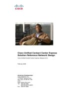
Corporate Headquarters
Cisco Systems, Inc.
170 West Tasman Drive
San Jose, CA 95134-1706
USA
Tel: 408 526-4000
800 553-NETS (6387)
Fax: 408 526-4100
Cisco AVVID Network Infrastructure:
Implementing 802.1w and 802.1s in
Campus Networks
Implementation Guide
April, 2003
Customer Order Number: 956652
THE SPECIFICATIONS AND INFORMATION REGARDING THE PRODUCTS IN THIS MANUAL ARE SUBJECT TO CHANGE WITHOUT NOTICE. ALL
STATEMENTS, INFORMATION, AND RECOMMENDATIONS IN THIS MANUAL ARE BELIEVED TO BE ACCURATE BUT ARE PRESENTED WITHOUT
WARRANTY OF ANY KIND, EXPRESS OR IMPLIED. USERS MUST TAKE FULL RESPONSIBILITY FOR THEIR APPLICATION OF ANY PRODUCTS.
THE SOFTWARE LICENSE AND LIMITED WARRANTY FOR THE ACCOMPANYING PRODUCT ARE SET FORTH IN THE INFORMATION PACKET THAT
SHIPPED WITH THE PRODUCT AND ARE INCORPORATED HEREIN BY THIS REFERENCE. IF YOU ARE UNABLE TO LOCATE THE SOFTWARE LICENSE
OR LIMITED WARRANTY, CONTACT YOUR CISCO REPRESENTATIVE FOR A COPY.
The Cisco implementation of TCP header compression is an adaptation of a program developed by the University of California, Berkeley (UCB) as part of UCB’s public
domain version of the UNIX operating system. All rights reserved. Copyright © 1981, Regents of the University of California.
NOTWITHSTANDING ANY OTHER WARRANTY HEREIN, ALL DOCUMENT FILES AND SOFTWARE OF THESE SUPPLIERS ARE PROVIDED “AS IS” WITH
ALL FAULTS. CISCO AND THE ABOVE-NAMED SUPPLIERS DISCLAIM ALL WARRANTIES, EXPRESSED OR IMPLIED, INCLUDING, WITHOUT
LIMITATION, THOSE OF MERCHANTABILITY, FITNESS FOR A PARTICULAR PURPOSE AND NONINFRINGEMENT OR ARISING FROM A COURSE OF
DEALING, USAGE, OR TRADE PRACTICE.
IN NO EVENT SHALL CISCO OR ITS SUPPLIERS BE LIABLE FOR ANY INDIRECT, SPECIAL, CONSEQUENTIAL, OR INCIDENTAL DAMAGES, INCLUDING,
WITHOUT LIMITATION, LOST PROFITS OR LOSS OR DAMAGE TO DATA ARISING OUT OF THE USE OR INABILITY TO USE THIS MANUAL, EVEN IF CISCO
OR ITS SUPPLIERS HAVE BEEN ADVISED OF THE POSSIBILITY OF SUCH DAMAGES.
Cisco AVVID Network Infrastructure: Implementing 802.1w and 802.1s in Campus Networks
Copyright © 2003, Cisco Systems, Inc.
All rights reserved.
CCIP, the Cisco Powered Network mark, the Cisco Systems Verified logo, Cisco Unity, Fast Step, Follow Me Browsing, FormShare, Internet Quotient, iQ Breakthrough, iQ
Expertise, iQ FastTrack, the iQ Logo, iQ Net Readiness Scorecard, Networking Academy, ScriptShare, SMARTnet, TransPath, and Voice LAN are trademarks of Cisco Systems,
Inc.; Changing the Way We Work, Live, Play, and Learn, Discover All That’s Possible, The Fastest Way to Increase Your Internet Quotient, and iQuick Study are service marks of
Cisco Systems, Inc.; and Aironet, ASIST, BPX, Catalyst, CCDA, CCDP, CCIE, CCNA, CCNP, Cisco, the Cisco Certified Internetwork Expert logo, Cisco IOS, the Cisco IOS logo,
Cisco Press, Cisco Systems, Cisco Systems Capital, the Cisco Systems logo, Empowering the Internet Generation, Enterprise/Solver, EtherChannel, EtherSwitch, GigaStack, IOS,
IP/TV, LightStream, MGX, MICA, the Networkers logo, Network Registrar, Packet, PIX, Post-Routing, Pre-Routing, RateMUX, Registrar, SlideCast, StrataView Plus, Stratm,
SwitchProbe, TeleRouter, and VCO are registered trademarks of Cisco Systems, Inc. and/or its affiliates in the U.S. and certain other countries.
All other trademarks mentioned in this document or Web site are the property of their respective owners. The use of the word partner does not imply a partnership relationship
between Cisco and any other company. (0201R)
iii
Cisco AVVID Network Infrastructure: Implementing 802.1w and 802.1s in Campus Networks
956652
CONTENTS
About this Guide vii
Intended Audience vii
Document Organization vii
Document Conventions viii
Obtaining Documentation viii
World Wide Web ix
Documentation CD-ROM ix
Ordering Documentation ix
Documentation Feedback ix
Obtaining Technical Assistance x
Cisco.com x
Technical Assistance Center x
CHAPTER
1 Introduction 1-1
Hierarchical Campus Networks 1-1
Data Centers 1-2
Wireless LANs 1-3
Spanning Tree Evolution 1-4
802.1D 1-4
Cisco 802.1D Enhancements 1-5
Rapid and Multiple Spanning Tree 1-5
CHAPTER
2 Understanding Rapid Spanning-Tree Protocol (802.1w) 2-1
New Port States and Port Roles 2-2
Port States 2-2
Port Roles 2-2
New BPDU Format 2-5
New BPDU Handling 2-6
Faster Aging of Information 2-6
Accepting Inferior BPDUs 2-6
Rapid Transition to Forwarding State 2-7
Edge Ports 2-7
Link Type 2-7
Convergence in 802.1D 2-7
Contents
iv
Cisco AVVID Network Infrastructure: Implementing 802.1w and 802.1s in Campus Networks
956652
Convergence in RSTP 2-9
Proposal/Agreement Handshake Sequence 2-10
New Topology Change Mechanisms 2-12
Topology Change Detection 2-13
Topology Change Propagation 2-13
Compatibility with 802.1D 2-14
CHAPTER
3 Understanding Multiple Spanning-Tree Protocol (802.1s) 3-1
Comparing MSTP with Other STPs 3-1
Per-VLAN Spanning Tree+ 3-2
Rapid Per-VLAN Spanning Tree+ 3-2
Standard 802.1q 3-2
Multiple Spanning Tree 3-3
MST Regions 3-4
MSTP Configuration and MST Region 3-5
Region Boundary 3-5
MST Instances 3-6
MSTIs 3-6
IST 3-7
MST Hop Count 3-8
Interaction Between the MST Region and the Outside World 3-9
Recommended Configuration 3-10
Alternate Configuration (Not Recommended) 3-11
Invalid Configuration 3-12
Common Misconfigurations 3-13
IST Instance is Active on All Ports, Whether Trunk or Access 3-13
Two VLANs Mapped to the Same Instance Will Block the Same Ports 3-14
CHAPTER
4 Deploying RSTP and MSTP 4-1
Data Center Topology 4-1
RSTP Active Topology 4-2
RSTP Convergence Example 4-2
RSTP Link Failure Recovery 4-5
Configuring Rapid-PVST+ 4-7
Configuring MSTP 4-9
MST Region 4-9
MAC Address Reduction 4-10
Configuring MSTP at the Distribution Level 4-11
Contents
v
Cisco AVVID Network Infrastructure: Implementing 802.1w and 802.1s in Campus Networks
956652
Configuring MSTP at the Access Layer 4-13
Interaction Between STPs 4-15
Rapid-PVST+ Interacting with PVST+ 4-15
Rapid-PVST+ Interacting with MSTP 4-16
MSTP Interaction (General) 4-16
IST Interacting with STP 4-16
IST Interacting with PVST+ 4-17
IST Interacting with 802.1q CST 4-19
RSTP in a Stack 4-20
Link Type 4-21
Migration Strategy 4-22
Spanning Tree Logical Ports 4-23
Spanning Tree Extensions 4-23
Spanning-Tree PortFast, BPDU Guard, and BPDU Filtering 4-23
Spanning-Tree Loop Guard 4-26
Contents
vi
Cisco AVVID Network Infrastructure: Implementing 802.1w and 802.1s in Campus Networks
956652
vii
Cisco AVVID Network Infrastructure: Implementing 802.1w and 802.1s in Campus Networks
956652
About this Guide
This document presents an overview of Rapid Spanning-Tree Protocol (RSTP) and Multiple
Spanning-Tree Protocol (MSTP) and how to implement each.
Intended Audience
This document is an implementation guide for deploying the recently ratified 802.1w (RSTP) and 802.1s
(MSTP) in enterprises where Layer 2 redundancy is required and spanning tree is used to prevent Layer
2 loops.
This document includes an over view of RSTP and MSTP as well as configuration examples,
implementation details, and a discussion of interoperability issues with legacy spanning tree.
Document Organization
This document contains the following chapters:
Chapter or Appendix Description
Chapter 1, “Introduction” Provides an introduction for this implementation guide.
Chapter 2, “Understanding
Rapid Spanning-Tree
Protocol (802.1w)”
Provides an overview of the RSTP (802.1w).
Chapter 3, “Understanding
Multiple Spanning-Tree
Protocol (802.1s)”
Provides an overview of the MSTP (802.1s).
Chapter 4, “Deploying
RSTP and MSTP”
Provides guidelines and examples for implementing RSTP and MSTP.
viii
Cisco AVVID Network Infrastructure: Implementing 802.1w and 802.1s in Campus Networks
956652
About this Guide
Document Conventions
Document Conventions
This guide uses the following conventions to convey instructions and information:
Note Means reader take note. Notes contain helpful suggestions or references to material not
covered in the manual.
Timesaver Means the described action saves time. You can save time by performing the action
described in the paragraph.
Tips Means the following information will help you solve a problem. The tips information might
not be troubleshooting or even an action, but could be useful information, similar to a
Timesaver.
Caution Means reader be careful. In this situation, you might do something that could result in
equipment damage or loss of data.
Obtaining Documentation
These sections explain how to obtain documentation from Cisco Systems.
Table 1 Document Conventions
Convention Description
boldface font Commands and keywords.
italic font Variables for which you supply values.
[ ] Keywords or arguments that appear within square brackets are optional.
{x | y | z} A choice of required keywords appears in braces separated by vertical bars. You must select one.
screen font
Examples of information displayed on the screen.
boldface screen
font
Examples of information you must enter.
< > Nonprinting characters, for example passwords, appear in angle brackets.
[ ] Default responses to system prompts appear in square brackets.
ix
Cisco AVVID Network Infrastructure: Implementing 802.1w and 802.1s in Campus Networks
956652
About this Guide
Obtaining Documentation
World Wide Web
You can access the most current Cisco documentation on the World Wide Web at this URL:
Translated documentation is available at this URL:
/>Documentation CD-ROM
Cisco documentation and additional literature are available in a Cisco Documentation CD-ROM
package, which is shipped with your product. The Documentation CD-ROM is updated monthly and may
be more current than printed documentation. The CD-ROM package is available as a single unit or
through an annual subscription.
Ordering Documentation
You can order Cisco documentation in these ways:
• Registered Cisco.com users (Cisco direct customers) can order Cisco product documentation from
the Networking Products MarketPlace:
/>• Registered Cisco.com users can order the Documentation CD-ROM through the online Subscription
Store:
/>• Nonregistered Cisco.com users can order documentation through a local account representative by
calling Cisco Systems Corporate Headquarters (California, U.S.A.) at 408 526-7208 or, elsewhere
in North America, by calling 800 553-NETS (6387).
Documentation Feedback
You can submit comments electronically on Cisco.com. In the Cisco Documentation home page, click
the Fax or Email option in the “Leave Feedback” section at the bottom of the page.
You can e-mail your comments to
You can submit your comments by mail by using the response card behind the front cover of your
document or by writing to the following address:
Cisco Systems
Attn: Document Resource Connection
170 West Tasman Drive
San Jose, CA 95134-9883
We appreciate your comments.
x
Cisco AVVID Network Infrastructure: Implementing 802.1w and 802.1s in Campus Networks
956652
About this Guide
Obtaining Technical Assistance
Obtaining Technical Assistance
Cisco provides Cisco.com as a starting point for all technical assistance. Customers and partners can
obtain online documentation, troubleshooting tips, and sample configurations from online tools by using
the Cisco Technical Assistance Center (TAC) Web Site. Cisco.com registered users have complete access
to the technical support resources on the Cisco TAC Web Site.
Cisco.com
Cisco.com is the foundation of a suite of interactive, networked services that provides immediate, open
access to Cisco information, networking solutions, services, programs, and resources at any time, from
anywhere in the world.
Cisco.com is a highly integrated Internet application and a powerful, easy-to-use tool that provides a
broad range of features and services to help you with these tasks:
• Streamline business processes and improve productivity
• Resolve technical issues with online support
• Download and test software packages
• Order Cisco learning materials and merchandise
• Register for online skill assessment, training, and certification programs
If you want to obtain customized information and service, you can self-register on Cisco.com. To access
Cisco.com, go to this URL:
Technical Assistance Center
The Cisco Technical Assistance Center (TAC) is available to all customers who need technical assistance
with a Cisco product, technology, or solution. Two levels of support are available: the Cisco TAC
Web Site and the Cisco TAC Escalation Center.
Cisco TAC inquiries are categorized according to the urgency of the issue:
• Priority level 4 (P4)—You need information or assistance concerning Cisco product capabilities,
product installation, or basic product configuration.
• Priority level 3 (P3)—Your network performance is degraded. Network functionality is noticeably
impaired, but most business operations continue.
• Priority level 2 (P2)—Your production network is severely degraded, affecting significant aspects
of business operations. No workaround is available.
• Priority level 1 (P1)—Your production network is down, and a critical impact to business operations
will occur if service is not restored quickly. No workaround is available.
The Cisco TAC resource that you choose is based on the priority of the problem and the conditions of
service contracts, when applicable.
xi
Cisco AVVID Network Infrastructure: Implementing 802.1w and 802.1s in Campus Networks
956652
About this Guide
Obtaining Technical Assistance
Cisco TAC Web Site
You can use the Cisco TAC Web Site to resolve P3 and P4 issues yourself, saving both cost and time.
The site provides around-the-clock access to online tools, knowledge bases, and software. To access the
Cisco TAC Web Site, go to this URL:
/>All customers, partners, and resellers who have a valid Cisco service contract have complete access to
the technical support resources on the Cisco TAC Web Site. The Cisco TAC Web Site requires a
Cisco.com login ID and password. If you have a valid service contract but do not have a login ID or
password, go to this URL to register:
/>If you are a Cisco.com registered user, and you cannot resolve your technical issues by using the Cisco
TAC Web Site, you can open a case online by using the TAC Case Open tool at this URL:
/>If you have Internet access, we recommend that you open P3 and P4 cases through the Cisco TAC
Web Site.
Cisco TAC Escalation Center
The Cisco TAC Escalation Center addresses priority level 1 or priority level 2 issues. These
classifications are assigned when severe network degradation significantly impacts business operations.
When you contact the TAC Escalation Center with a P1 or P2 problem, a Cisco TAC engineer
automatically opens a case.
To obtain a directory of toll-free Cisco TAC telephone numbers for your country, go to this URL:
/>Before calling, please check with your network operations center to determine the level of Cisco support
services to which your company is entitled: for example, SMARTnet, SMARTnet Onsite, or Network
Supported Accounts (NSA). When you call the center, please have available your service agreement
number and your product serial number.
xii
Cisco AVVID Network Infrastructure: Implementing 802.1w and 802.1s in Campus Networks
956652
About this Guide
Obtaining Technical Assistance
CHAPTER
1-1
Cisco AVVID Network Infrastructure: Implementing 802.1w and 802.1s in Campus Networks
956652
1
Introduction
This chapter provides an overview of the situations where Layer 2 loops may exist in campus networks
and the tools that are available to address these loops.
Hierarchical Campus Networks
For campus networks, Cisco recommends a hierarchical network design that distributes networking
function at each layer through a layered organization. The hierarchical model enables the design of a
modular topology using “building blocks” that are scalable and allow the network to meet evolving
business needs.
The hierarchical model is based on a modular design, which is easy to scale, understand, and
troubleshoot because it follows a deterministic traffic pattern. The principle advantages of the
hierarchical model are:
• Hierarchy—With a hierarchical design, flows get larger as they traverse points of aggregation and
move up the hierarchy. Functions are distributed at each layer in an optimal way through a layered
organization. And a hierarchical design avoids the need for a fully meshed network, in which all
devices are connected to each other. This promotes scalability.
• Modularity—Modular networks are made from building blocks, which are easy to replicate,
redesign, and grow. Each time a module is added or taken out, there should be no need to redesign
the whole network. Distinct blocks can be put in-service and taken out-of-service without impacting
other blocks or the core of the network. This greatly enhances the ease of troubleshooting, problem
isolation, and network management.
Cisco introduced the hierarchical design model in 1999. This model, shown in Figure 1-1, uses a layered
approach with the primary components being the access layer, the distribution layer, and the core
(backbone) layer. Server farms (data centers), WANs, Internet connections, and PSTNs can be plugged
in as building blocks in this model.
1-2
Cisco AVVID Network Infrastructure: Implementing 802.1w and 802.1s in Campus Networks
956652
Chapter 1 Introduction
Hierarchical Campus Networks
Figure 1-1 Hierarchical Campus Network Design
Cisco recommends that campus designs avoid the use of Layer 2 loops whenever possible. With the
advent of hardware-accelerated, Layer 3 switches, which offer intelligent network services (INS) and
routing at Layer 2 switching rates, there are few reasons to extend a Layer 2 domain across campus.
However, there are two situations in which Layer 2 loops might be unavoidable and a Spanning Tree
Protocol (STP) must be used. These situations include the use of:
• Data Centers
• Wireless LANs
Data Centers
A data center houses server farms, which consist of a logical group of networked servers. These servers
are tasked with handling various processes, like those of web, application, and database services. Server
farms often take advantage of other infrastructure devices, such as Content Switches, Content Engines,
and Secure Sockets Layer (SSL) appliances, to assist in offloading the processing requirements of
individual servers and the server farm as a whole.
Access
Distribution
Building block
additions
WAN Internet PSTN
76765
VLAN G
VLAN A Data
VLAN B Voice
VLAN G WLAN
VLAN C Data
VLAN D Voice
VLAN G WLAN
VLAN E Data
VLAN F Voice
VLAN G WLAN
VLAN T, U
VLAN T, U
VLAN T, U VLAN T, U
Data center
VLAN H Data
VLAN I Voice
VLAN J Data
VLAN K Voice
VLAN L Data
VLAN M Voice
VLAN N Data
VLAN O Voice
VLAN P Data
VLAN Q Voice
VLAN R Data
VLAN S Voice
Backbone
Core
1-3
Cisco AVVID Network Infrastructure: Implementing 802.1w and 802.1s in Campus Networks
956652
Chapter 1 Introduction
Hierarchical Campus Networks
Designing a data center is different from designing a standard Distribution-Access layer block for end
users. When using dual-homed servers, it is necessary to have the same Layer 2 VLAN appear in
multiple devices (as shown in Figure 1-2). This means that a Spanning Tree, such as 802.1D or 802.1w,
is required to create a loop-free Layer 2 topology.
Figure 1-2 Data Centers and Layer 2 Loops
Wireless LANs
Wireless LANs enable users to connect to a network from any location within an enterprise. However,
moving (or roaming) from one wireless access point (AP) to another without being dropped is not
possible if the APs are in different IP subnets—unless Mobile IP is used. To avoid the complexities of
Mobile IP, APs can be located in within the same Layer 2 domain, or VLAN, to provide the fastest
roaming time for mobile end stations. This means that the wireless VLAN must exist in the entire
building or even an entire campus. Because the devices in the wiring closet should be redundantly
connected for availability, this introduces the likelihood of Layer 2 loops (as shown in Figure 1-3).
Therefore, a Spanning Tree, such as 802.1D or 802.1w, is required to create a loop-free Layer 2 topology.
Aggregation-1
(root)
76766
Server
Server
Aggregation-2
(secondary root)
Campus Core
Trunk
Front End-1
Front End-2
Content service modules
(content switch, content
engine, SSL appliance)
Content service modules
(content switch, content
engine, SSL appliance)
VLAN X
VLAN X
VLAN X
VLAN X
1-4
Cisco AVVID Network Infrastructure: Implementing 802.1w and 802.1s in Campus Networks
956652
Chapter 1 Introduction
Spanning Tree Evolution
Figure 1-3 WLAN s and Layer 2 Loops
Spanning Tree Evolution
For many years, STP existed as an unenhanced standard. In recent years, however, the protocol has seen
many enhancements and changes.
802.1D
Initially, redundant switched networks had to rely on the relatively sluggish 802.1D STP to address the
problems of Layer 2 loops. The 802.1D standard was designed by the Institute of Electrical and
Electronics Engineers (IEEE) at a time where recovering connectivity (and cycling through the STP
states, shown in Figure 1-4) after an outage within a minute or so was considered adequate performance.
As the tolerance level for outages reduced, maintaining 802.1D often turned out to be the network
administrator's most challenging task, as tuning the protocol timers was the only way to get a few
seconds of faster convergence, but often to the detriment of the network's stability.
To core To core
Layer 3
Data, Voice
and Wireless
VLAN trunk
Access layer
Distribution layer
VLAN X WLAN
VLAN A Data
VLAN B Voice
VLAN X WLAN
VLAN C Data
VLAN D Voice
VLAN X WLAN
VLAN E Data
VLAN F Voice
87380
VLAN X
1-5
Cisco AVVID Network Infrastructure: Implementing 802.1w and 802.1s in Campus Networks
956652
Chapter 1 Introduction
Spanning Tree Evolution
Figure 1-4 802.1D Cycle
Cisco 802.1D Enhancements
In the late 1990s, Cisco enhanced the original 802.1D specification with features such as UplinkFast,
BackboneFast, and PortFast to speed up the convergence time of a bridged network.
• UplinkFast is an access-layer STP solution that provides fast failover when the root port or root
switch fails.
• BackboneFast is a distribution and access-layer STP solution that provides fast convergence in the
network for indirect link failures.
• PortFast is an access-layer STP solution that causes a port to enter the spanning tree forwarding state
immediately, bypassing the listening and learning states.
The drawback of these mechanisms is that they are proprietary and require additional configuration.
Cisco also answered the scalability issues of Layer 2 based networks by developing the Multiple
Instance Spanning Tree Protocol (MISTP).
Rapid and Multiple Spanning Tree
In 1999, the IEEE decided to incorporate most of these concepts into two standards, which were ratified
in 2002: Rapid Spanning-Tree Protocol (RSTP; 802.1w) and Multiple Spanning-Tree Protocol (MSTP;
802.1s). Using these new protocols, convergence times in the hundreds of milliseconds can be expected
while scaling to thousands of VLANs.
Cisco remains the leader in the industry by offering these two protocols in addition to the proprietary
STP enhancements (discussed in the previous section) to facilitate the migration and interoperability
with legacy bridges.
The remainder of this document provides an overview of the new spanning-tree protocols and how they
should be implemented in enterprises that use the multilayer design model.
87105
Listening
LinkUp
20 seconds
(max-age)
Blocking
State Transition
Forwarding
15 seconds
Learning
15 seconds
(fwd-delay)
802.1D
(STP)
1-6
Cisco AVVID Network Infrastructure: Implementing 802.1w and 802.1s in Campus Networks
956652
Chapter 1 Introduction
Spanning Tree Evolution
CHAPTER
2-1
Cisco AVVID Network Infrastructure: Implementing 802.1w and 802.1s in Campus Networks
956652
2
Understanding Rapid Spanning-Tree Protocol
(802.1w)
Rapid Spanning-Tree Protocol (RSTP; IEEE 802.1w) is an evolution of the IEEE 802.1D standard.
RSTP is a Layer 2 loop prevention algorithm like 802.1D. However, RSTP achieves rapid failover and
convergence times in many situations, such as switch failure, cable failure, and topology change for
Layer 2 networks.
RSTP is not a timer-based spanning tree algorithm (STA) like 802.1D. Therefore, RSTP offers an
improvement over the 30 seconds or more that 802.1D takes to move a link to forwarding. The heart of
the protocol is a new bridge-bridge handshake mechanism, which allows ports to move directly to
forwarding.
RSTP is now the recommended STA for resilient networks relying on Layer 2 cable paths for
redundancy. It is backwardly compatible with 802.1D, transparent to end users, and more importantly
standards based. Some of the enhancements in RSTP are achieved through the introduction of:
• New port role assignments and port states
• New BPDU format and BPDU processing
• A bridge-bridge handshake mechanism, which rapidly determines protocol state for the link
• A different Topology Change Notification and processing procedure
The 802.1D terminology remains primarily the same and most parameters have been left unchanged.
Therefore, users familiar with 802.1D can quickly and easily configure the new protocol. 802.1w is also
capable of reverting back to 802.1D in order to interoperate with legacy bridges (thus dropping the
benefits it introduces) on a per-port basis.
This chapter provides an overview of the enhancements added by RSTP to the previous 802.1D standard.
Note RSTP was first implemented as part of Multiple Spanning-Tree Protocol (MSTP) in Catalyst OS 7.1 and
IOS software release 12.1(11)EX and later. It is currently available as a standalone protocol with the
Rapid Per-VLAN-Spanning-Tree Plus (Rapid-PVST+) mode on the Catalyst 6000 in IOS software
release 12.1(13)E and Catalyst OS 7.4, on the Catalyst 3550 switch in IOS software release
12.1(13)EA1, and on the Catalyst 4000 in Catalyst OS 7.4. In this mode, the switch runs an RSTP
instance on each VLAN.
2-2
Cisco AVVID Network Infrastructure: Implementing 802.1w and 802.1s in Campus Networks
956652
Chapter 2 Understanding Rapid Spanning-Tree Protocol (802.1w)
New Port States and Port Roles
New Port States and Port Roles
802.1D defined four different port states: listening, learning, blocking, and forwarding. This was a bit
confusing because it mixed the state of a port (whether it blocks or forwards traffic) and the role it plays
in the active topology (root port, designated port, and so on). For example, from an operational point of
view, there is no difference between a port in blocking state and a port in listening state; they both discard
frames and do not learn MAC addresses. The real difference lies in the role that the spanning tree assigns
to the port. It can safely be assumed that a listening port is either designated or root and is on its way to
the forwarding state. Unfortunately, once in forwarding state, there is no way to infer from the port state
whether the port is root or designated. RSTP addresses this confusion by decoupling the role and the
state of a port.
Note RSTP calculates the final topology for the spanning tree using the same criteria as 802.1D. There is no
change in the way the different bridge and port priorities are used.
Port States
There are only three port states in RSTP, which correspond to the three possible operational states.
• Learning
• Forwarding
• Discarding
The 802.1D states disabled, blocking, and listening have been merged into a unique 802.1w discarding
state.
Note In the Cisco implementation, the name blocking is used for the discarding state. Catalyst OS release 7.1
and later still display the listening and learning states, giving even more information about a port than
the IEEE standard requires. However, there now is a difference between the role the protocol has
determined for a port and its current state. For example, it is now perfectly valid for a port to be
designated and blocking at the same time. While this will typically happen for very short periods of time,
it simply means that this port is in a transitory state towards designated forwarding.
Port Roles
The role is now a variable assigned to a given port. The root port and designated port roles remain. The
blocking port role is now split into the backup and alternate port roles. The STA determines the role of
a port based on an examination of the Bridge Protocol Data Units (BPDUs) to decide whether one is
more useful than the other. This decision is based on the value stored in the BPDU (and occasionally on
the port on which they are received). The value of the BPDU then determines the role of the port, as
explained in the following sections.
2-3
Cisco AVVID Network Infrastructure: Implementing 802.1w and 802.1s in Campus Networks
956652
Chapter 2 Understanding Rapid Spanning-Tree Protocol (802.1w)
New Port States and Port Roles
Root Port Roles
With STP, the STA elects a single root bridge for the whole bridged network (per-VLAN). The root
bridge sends BPDUs that are more useful than the ones that any other bridge can send. The port receiving
the best BPDU on a bridge is the root port. This is the port that is the closest to the root bridge in terms
of path cost.
Figure 2-1 Root Port
Note The root bridge is the only bridge in the network that does not have a root port. All other bridges receive
BPDUs on at least one port.
Designated Port Role
802.1D bridges create a bridged domain by linking together different segments (Ethernet segments, for
example). On any given segment, there can be only one path toward the root bridge. If there were two,
there would be a bridging loop in the network. All bridges connected to a given segment listen to each
other's BPDUs and agree on the bridge sending the best BPDU as the designated bridge for the segment.
The corresponding port on that bridge is the designated port.
A
B
Root
76747
R
R
R - Root port
2-4
Cisco AVVID Network Infrastructure: Implementing 802.1w and 802.1s in Campus Networks
956652
Chapter 2 Understanding Rapid Spanning-Tree Protocol (802.1w)
New Port States and Port Roles
Figure 2-2 Designated Port
Alternate and Backup Port Roles
These two port roles correspond to the blocking state of 802.1D. A blocked port is defined as any port
that is not the designated or root port. A port remains blocked as long as it receives more useful BPDUs
than the one it would send out on its segment. Therefore, a port must receive BPDUs in order to stay
blocked.
With RSTP, there are two types of blocked ports.
• An alternate port is a port that is blocked because it is receiving more useful BPDUs from another
bridge, as shown in Figure 2-3.
Figure 2-3 Alternate Port
• A backup port is a port that is blocked because it is receiving more useful BPDUs from the same
bridge it is on, as shown in Figure 2-4.
A
B
Root
76748
R
R
R - Root port
D - Designated port
D
D
D
A
B
Root
76749
R
R
R - Root port
D - Designated port
D
D
D
Alternate
port
2-5
Cisco AVVID Network Infrastructure: Implementing 802.1w and 802.1s in Campus Networks
956652
Chapter 2 Understanding Rapid Spanning-Tree Protocol (802.1w)
New BPDU Format
Figure 2-4 Backup Port
This distinction was already made internally within 802.1D and this is essentially how Cisco's
UplinkFast feature functions. The rationale behind this is that an alternate port provides an alternate path
to the root bridge and could, therefore, replace the root port should it fail. A backup port provides
redundant connectivity to the same segment and cannot guarantee an alternate connectivity to the root
bridge.
New BPDU Format
A few changes to the BPDU format have been introduced by RSTP (as shown in Figure 2-5). Only two
flags, Topology Change (TC) and TC Acknowledgment (TCA), were defined in 802.1D. However, RSTP
now uses the six remaining bits of the flag byte to do the following:
• Encode the role and state of the port from which the BPDU originated
• Handle the proposal/agreement mechanism
Figure 2-5 RSTP BPDU Format
A
B
Root
76750
R
R
R - Root port
D - Designated port
D
D
D
Backup
port
76751
Bit 7-Topology Change ACK
Bit 0-Topology Change
Protocol ID (2 Bytes)
Version (1 Byte)
Root ID (8 Bytes)
Path Cost (4 Bytes)
Bridge ID (8 Bytes)
Port ID (2 Bytes)
Message Age (2 Bytes)
Maximum Age (2 Bytes)
Hello Time (2 Bytes)
Forwarding Delay (2 Bytes)
Message Type (1 Byte)
Flags (1 Byte)
Version 1 Length (2 Bytes)
Updated Field
Configurable
Root Set and
Configurable
Bit 1-Proposal
Bit 4-Learning
Bit 5-Forwarding
Bit 6-Agreement
Bit 2-3-Port role
00 Unknown
01 Alternate/backup
10 Root
11 Designated
2-6
Cisco AVVID Network Infrastructure: Implementing 802.1w and 802.1s in Campus Networks
956652
Chapter 2 Understanding Rapid Spanning-Tree Protocol (802.1w)
New BPDU Handling
Another important change is that the RSTP BPDU is now of Type 2, Version 2. The implication of this
is that legacy bridges must drop this new BPDU. This makes it easy for a 802.1w bridge to detect the
legacy bridges connected to it. RSTP BPDUs are of Type 2, Version 2 and MST BPDUs are Type 2,
Version 3 format.
Note BPDUs are sent to the same IEEE MAC address.
New BPDU Handling
With 802.1D, a non-root bridge only generates BPDUs when it receives one on its root port. In fact, with
802.1D, a bridge relays BPDUs instead of generating them.
With 802.1w, a bridge sends a BPDU with its current information at the hello time interval (2 seconds
by default), even if it does not receive any BPDUs from the root bridge.
Faster Aging of Information
In 802.1D on any given port, if BPDUs are not received before the max_age timer (20 seconds, by
default) expires, the protocol information is aged out. With 802.1w, BPDUs are now used as a keep-alive
mechanism between bridges. If a bridge misses three BPDUs in a row, it considers the connection to its
direct neighboring root or designated bridge to be lost and immediately ages out the protocol
information. This is in contrast to 802.1D where the problem could have been anywhere on the path to
the root. This fast aging of the information allows for quick failure detection.
Note Failures are detected even faster in the case of a physical link failure.
Accepting Inferior BPDUs
Accepting inferior BPDUs is what makes up the core of the BackboneFast feature. The IEEE 802.1w
committee decided to incorporate a similar mechanism into RSTP. When a bridge receives inferior
information from its designated or root bridge, it immediately accepts it and replaces the one previously
stored, as shown in Figure 2-6.
Figure 2-6 Inferior BPDUs
Root
B
C
76752
Inferior BPDU
"I am the root"
2-7
Cisco AVVID Network Infrastructure: Implementing 802.1w and 802.1s in Campus Networks
956652
Chapter 2 Understanding Rapid Spanning-Tree Protocol (802.1w)
Rapid Transition to Forwarding State
Because Bridge C still knows the root is alive and well, it immediately sends a BPDU to Bridge B
containing information about the root bridge. As a result, Bridge B stops sending its own BPDUs and
accepts the port leading to Bridge C as its new root port.
Rapid Transition to Forwarding State
Rapid transition is the most important feature introduced by 802.1w. The legacy STA passively waited
for the network to converge before moving a port into the forwarding state. Achieving faster convergence
was a matter of tuning the conservative default parameters (forward delay and max_age timers), often
sacrificing the stability of the network.
RSTP is able to actively confirm that a port can safely transition to forwarding without relying on any
timer configuration. There is a feedback mechanism that operates between RSTP-compliant bridges. To
achieve fast convergence on a port, the RSTP relies on two new variables: edge ports and link type.
Edge Ports
The edge port concept is already well known to Cisco's spanning tree users as it basically corresponds
to the PortFast feature. The idea is that ports that are directly connected to end stations cannot create
bridging loops in the network and can thus directly transition to forwarding, skipping the listening and
learning stages. An edge port does not generate topology changes when its link toggles. Unlike PortFast
though, an edge port that receives a BPDU immediately loses its edge port status and becomes a normal
spanning-tree port. At this point, there is a user-configured value and an operational value for the edge
port state.
In Cisco's implementation, the portfast command is used for edge port configuration, thus making the
transition to RSTP simpler.
For more information about the portfast command, see the “PortFast” section on page 4-23.
Link Type
RSTP can only achieve rapid transition to forwarding on edge ports and on point-to-point links. The link
type is automatically derived from the duplex mode of a port. A port operating in full-duplex will be
assumed to be point-to-point, while a half-duplex port will be considered as a shared port by default.
This automatic link type setting can be overridden by explicit configuration.
In today's switched networks, most links are operating in full-duplex mode and are therefore treated as
point-to-point links by RSTP. This makes them candidates for rapid transition to forwarding.
Convergence in 802.1D
In this scenario, a link between the root bridge and Bridge A has just been added. Let’s assume there was
already an indirect connection between Bridge A and the root bridge (via Bridge C to Bridge D in the
diagram). The STA disables the bridging loop by blocking a port.
1. As they are just coming up, both ports on the link between the root and A are put in listening state.
Bridge A is now able to hear the root directly and it immediately propagates its BPDUs on its
designated port (as shown in Figure 2-7).