Tài liệu Lab 5.1.3 Connecting Router LAN Interfaces pdf
Bạn đang xem bản rút gọn của tài liệu. Xem và tải ngay bản đầy đủ của tài liệu tại đây (103.33 KB, 2 trang )
1 - 2 CCNA 1: Networking Basics v 3.0 - Lab 5.1.3 Copyright 2003, Cisco Systems, Inc.
Lab 5.1.3 Connecting Router LAN Interfaces
Objective
• Identify the Ethernet or Fast Ethernet interfaces on the router
• Identify and locate the proper cables to connect the router and PC to a hub or switch
• Use the cables to connect the router and PC to the hub or switch
Background / Preparation
This lab focuses on the ability to connect the physical cabling between Ethernet LAN devices such
as hubs and switches and the appropriate Ethernet interface on a router. The computer(s) and router
should be preconfigured with the correct IP network settings. Start this lab with the computer(s),
router, and the hub or switch all turned off and unplugged. The following resources will be required:
• At least one workstation with an Ethernet 10/100 NIC installed
• One Ethernet switch or hub
• One router with an RJ-45 Ethernet or Fast Ethernet interface or an AUI interface
• 10BASE-T AUI transceiver (DB15 to RJ45) for a router with an AUI Ethernet interface (2500
Series)
• Several Ethernet cables, which are straight-through and crossover, to choose from for
connecting the workstation and router to the hub or switch.
Step 1 Identify the Ethernet or FastEthernet interfaces on the router
a. Examine the router.
What is the model number of the router?
_______________________________________________
b. Locate one or more RJ45 connectors on the router labeled “10/100 Ethernet”. This identifier may
vary depending on the type of router used. A 2500 series router will have an AUI DB15 Ethernet
or
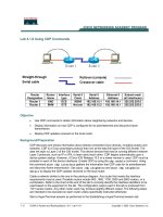
Crossover cable
Straight-through cable
Serial cable
Rollover or console
cable
2 - 2 CCNA 1: Networking Basics v 3.0 - Lab 5.1.3 Copyright 2003, Cisco Systems, Inc.
port labeled AUI 0. These will require a 10BASE-T transceiver to connect to the RJ45 cable.
c. Identify the Ethernet ports shown that could be used for connecting the routers. Record the
information below. Record the AUI port numbers if a Cisco 2500 series router is being used.
Router Port Port
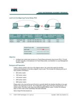
Step 2 Identify the proper cables and connect router
a. The connection between the router and the hub will be accomplished using a CAT 5 straight-
through patch cable. Locate a patch cable that is long enough to reach from the router to the
hub. Be sure to examine the cable ends carefully and select only straight through cables.
b. Use a cable to connect the Ethernet interface that uses zero designation on the router to a port
on the hub or switch. Also use the 10BASE-T AUI transceiver for the 2500 series.
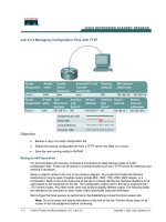
Step 3 Connect the workstation Ethernet cabling
a. The computer(s) will also connect to the hub using a straight-through patch cable. Run CAT 5
patch cables from each PC to where the switch or hub is located. Connect one end of these
cables to the RJ45 connector on the computer NIC and connect the other end to a port on the
hub or switch. Be sure to examine the cable ends carefully and select only straight-through
cables.
Step 4 Verifying the connection
a. Plug in and turn on the routers, computers, and hub or switch.
b. To verify the router connections, insure that the link light on the router interface and the
hub/switch interface are both lit.
c. To verify the computer connections, insure that the link light on the NIC and the hub interface are
both lit.