Tài liệu Ambit and Envisia Tutorial doc
Bạn đang xem bản rút gọn của tài liệu. Xem và tải ngay bản đầy đủ của tài liệu tại đây (301.98 KB, 45 trang )
Ambit and Envisia Tutorial
Product Version 4.0
August 2000
1999-2000 Cadence Design Systems, Inc. All rights reserved.
Printed in the United States of America.
Cadence Design Systems, Inc., 555 River Oaks Parkway, San Jose, CA 95134, USA
Trademarks: Trademarks and service marks of Cadence Design Systems, Inc. (Cadence) contained in this
document are attributed to Cadence with the appropriate symbol. For queries regarding Cadence’s trademarks,
contact the corporate legal department at the address shown above or call 1-800-862-4522.
All other trademarks are the property of their respective holders.
Restricted Print Permission: This publication is protected by copyright and any unauthorized use of this
publication may violate copyright, trademark, and other laws. Except as specified in this permission statement,
this publication may not be copied, reproduced, modified, published, uploaded, posted, transmitted, or
distributed in any way, without prior written permission from Cadence. This statement grants you permission to
print one (1) hard copy of this publication subject to the following conditions:
1. The publication may be used solely for personal, informational, and noncommercial purposes;
2. The publication may not be modified in any way;
3. Any copy of the publication or portion thereof must include all original copyright, trademark, and other
proprietary notices and this permission statement; and
4. Cadence reserves the right to revoke this authorization at any time, and any such use shall be
discontinued immediately upon written notice from Cadence.
Disclaimer: Information in this publication is subject to change without notice and does not represent a
commitment on the part of Cadence. The information contained herein is the proprietary and confidential
information of Cadence or its licensors, and is supplied subject to, and may be used only by Cadence’s customer
in accordance with, a written agreement between Cadence and its customer. Except as may be explicitly set
forth in such agreement, Cadence does not make, and expressly disclaims, any representations or warranties
as to the completeness, accuracy or usefulness of the information contained in this document. Cadence does
not warrant that use of such information will not infringe any third party rights, nor does Cadence assume any
liability for damages or costs of any kind that may result from use of such information.
Restricted Rights: Use, duplication, or disclosure by the Government is subject to restrictions as set forth in
FAR52.227-14 and DFAR252.227-7013 et seq. or its successor.
Ambit and Envisia Synthesis Tutorial
August 2000 2 Product Version 4.0
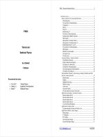
1
Introduction . . . . . . . . . . . . . . . . . . . . . . . . . . . . . . . . . . . . . . . . . . . . . . . . . . . . . . . . . . . . 4
Ambit BuildGates . . . . . . . . . . . . . . . . . . . . . . . . . . . . . . . . . . . . . . . . . . . . . . . . . . . . . . . . 5
Envisia Timing Analysis . . . . . . . . . . . . . . . . . . . . . . . . . . . . . . . . . . . . . . . . . . . . . . . . . . . 6
Envisia Test Synthesis . . . . . . . . . . . . . . . . . . . . . . . . . . . . . . . . . . . . . . . . . . . . . . . . . . . . 7
The CPU Example . . . . . . . . . . . . . . . . . . . . . . . . . . . . . . . . . . . . . . . . . . . . . . . . . . . . . . . 8
Defining Environment Variables . . . . . . . . . . . . . . . . . . . . . . . . . . . . . . . . . . . . . . . . . . . . . 9
More Information . . . . . . . . . . . . . . . . . . . . . . . . . . . . . . . . . . . . . . . . . . . . . . . . . . . . . . . . 9
2
Synthesizing a Design from the Top Down . . . . . . . . . . . . . . . . . . . . . . . . . . . . . . . . 10
Invoking the Synthesis Tool . . . . . . . . . . . . . . . . . . . . . . . . . . . . . . . . . . . . . . . . . . . . . . . 10
Reading a Technology Library . . . . . . . . . . . . . . . . . . . . . . . . . . . . . . . . . . . . . . . . . . . . . 10
Reading the Design Modules . . . . . . . . . . . . . . . . . . . . . . . . . . . . . . . . . . . . . . . . . . . . . . 11
Building a Generic Netlist . . . . . . . . . . . . . . . . . . . . . . . . . . . . . . . . . . . . . . . . . . . . . . . . 11
Setting Timing Constraints . . . . . . . . . . . . . . . . . . . . . . . . . . . . . . . . . . . . . . . . . . . . . . . . 12
Defining Data Arrival and Required Times . . . . . . . . . . . . . . . . . . . . . . . . . . . . . . . . . . . 13
Optimizing the Design . . . . . . . . . . . . . . . . . . . . . . . . . . . . . . . . . . . . . . . . . . . . . . . . . . . 14
Generating a Timing Report . . . . . . . . . . . . . . . . . . . . . . . . . . . . . . . . . . . . . . . . . . . . . . 15
Saving the Netlist . . . . . . . . . . . . . . . . . . . . . . . . . . . . . . . . . . . . . . . . . . . . . . . . . . . . . . . 17
Exiting from Ambit BuildGates . . . . . . . . . . . . . . . . . . . . . . . . . . . . . . . . . . . . . . . . . . . . . 17
3
Creating a Flattened Netlist . . . . . . . . . . . . . . . . . . . . . . . . . . . . . . . . . . . . . . . . . . . . . 19
Invoking the GUI . . . . . . . . . . . . . . . . . . . . . . . . . . . . . . . . . . . . . . . . . . . . . . . . . . . . . . . 19
Reading a Technology Library . . . . . . . . . . . . . . . . . . . . . . . . . . . . . . . . . . . . . . . . . . . . . 20
Reading the Design Modules and Building the Generic Netlist . . . . . . . . . . . . . . . . . . . . 21
Defining the Timing Constraints . . . . . . . . . . . . . . . . . . . . . . . . . . . . . . . . . . . . . . . . . . . . 24
Optimizing the Netlist . . . . . . . . . . . . . . . . . . . . . . . . . . . . . . . . . . . . . . . . . . . . . . . . . . . . 28
Flattening the Netlist . . . . . . . . . . . . . . . . . . . . . . . . . . . . . . . . . . . . . . . . . . . . . . . . . . . . 30
Generating the Timing Report . . . . . . . . . . . . . . . . . . . . . . . . . . . . . . . . . . . . . . . . . . . . . 31
Saving the Netlist . . . . . . . . . . . . . . . . . . . . . . . . . . . . . . . . . . . . . . . . . . . . . . . . . . . . . . . 32
Exiting from the GUI . . . . . . . . . . . . . . . . . . . . . . . . . . . . . . . . . . . . . . . . . . . . . . . . . . . . 33
Contents
Ambit and Envisia Synthesis Tutorial
August 2000 3 Product Version 4.0
4
Synthesizing a Design from the Bottom Up . . . . . . . . . . . . . . . . . . . . . . . . . . . . . . . 34
Preparing for Synthesis . . . . . . . . . . . . . . . . . . . . . . . . . . . . . . . . . . . . . . . . . . . . . . . . . . 34
Setting the Ideal Clock . . . . . . . . . . . . . . . . . . . . . . . . . . . . . . . . . . . . . . . . . . . . . . . . . . . 35
Synthesizing Individual Design Blocks . . . . . . . . . . . . . . . . . . . . . . . . . . . . . . . . . . . . . . . 35
Generating a Netlist for the Top Module in the Design . . . . . . . . . . . . . . . . . . . . . . . . . . 37
5
Inserting a Scan Chain . . . . . . . . . . . . . . . . . . . . . . . . . . . . . . . . . . . . . . . . . . . . . . . . . 38
Preparing for Synthesis . . . . . . . . . . . . . . . . . . . . . . . . . . . . . . . . . . . . . . . . . . . . . . . . . . 38
Setting Test Synthesis Assertions . . . . . . . . . . . . . . . . . . . . . . . . . . . . . . . . . . . . . . . . . . 39
Adding the Scan Logic . . . . . . . . . . . . . . . . . . . . . . . . . . . . . . . . . . . . . . . . . . . . . . . . . . . 39
Setting Timing Constraints and Optimizing the Design . . . . . . . . . . . . . . . . . . . . . . . . . . 40
Connecting the Scan Chain . . . . . . . . . . . . . . . . . . . . . . . . . . . . . . . . . . . . . . . . . . . . . . . 40
Saving the Netlist and Exiting . . . . . . . . . . . . . . . . . . . . . . . . . . . . . . . . . . . . . . . . . . . . . 41
Viewing the Scan Chain File . . . . . . . . . . . . . . . . . . . . . . . . . . . . . . . . . . . . . . . . . . . . . . 42
Glossary 44
Ambit and Envisia Synthesis Tutorial
August 2000 4 Product Version 4.0
1
Introduction
Synthesis
is the process by which you convert a design written at the register-transfer level
(RTL) into a gate-level netlist. The RTL specification is written in Verilog or VHDL, using
high-level constructs such as for loops and case statements. The synthesis tool transforms
this RTL specification into a set of logic gates,such as AND, OR, and BUF, that are connected
in a network.
To specify the gates that the synthesis tool uses to build a netlist, you need to choose a
technology from a specific vendor. The vendor that you have chosen to fabricate your chip or
system supplies a technology library for you to use in synthesis. The technology library
defines the physical properties of the gates, including the amount of time that is required for
a signal to pass through each gate.
In addition to creating a gate-level netlist, the synthesis tool can perform the following
functions:
■ Analyze the timing of the netlist to ensure that no timing errors can occur.
■ Optimize the design for either the best performance or the smallest size.
■ Automatically insert a chain of scan elements or test signals into the netlist.
Figure 1-1 on page 5 shows how you can use the Ambit® and Envisia® synthesis tools to
develop a design, from an RTL description through test insertion. These are the steps that
are covered in this tutorial. However, you can also use the Ambit and Envisia tools during the
back-end development process. Layout and floor planning tools, for example, are also
supported by the Ambit and Envisia tools.
Ambit and Envisia Synthesis Tutorial
Introduction
August 2000 5 Product Version 4.0
Figure 1-1 Design Stages from Synthesis through Scan Insertion
Ambit BuildGates
You can use Ambit® BuildGates® to generate optimized gate-level netlists from your RTL
models, as follows:
1. Read your technology library into the synthesis database.
2. Read the HDL source code for your design, written in Verilog or VHDL, into the synthesis
database.
3. Generate a generic netlist based on the generic Ambit library.
4. Map the generic netlist to cells in the technology library and optimize the netlist.
These steps are illustrated in
Figure 1-2 on page 5.
Figure 1-2 Synthesis Steps
Ambit
BuildGates
RTL
Model
Gate- level
Netlist
Modified
Netlist
Envisia timing
analysis
Modified
Netlist
Envisia test
synthesis
RTL
model
Generic
netlist
Optimize
Optimized
netlist
Generic
Ambit library
Technology
library
Build a generic
database
Ambit and Envisia Synthesis Tutorial
Introduction
August 2000 6 Product Version 4.0
Ambit BuildGates has both a command-line interface and a graphical user interface (GUI).
Both provide the same synthesis functions. The GUI provides the following additional
features:
■ Module browser—Displays the design hierarchy. You can navigate through the hierarchy,
and perform operations on the hierarchy, such as setting the top module or dissolving
modules and branches in the hierarchy.
■ Source code editor—Gives you access to your HDL source files. You can load any
changes that you make to the source files back into the synthesis tool, and generate a
new netlist with those changes.
■ Schematic viewer—Displays your design in schematic form. You can pan and zoom,
display fanin and fanout cones, and display critical paths and timing values. You can
group instances, dissolve instances, or change the reference point of an instance.
■ Report viewer—Displays timing reports, area reports, and other reports that are
generated during your synthesis session.
■ TCL editor—Lets you create, edit, save, and source your TCL scripts.
■ ac_shell console—Lets you use the command-line interface from within the graphical
user interface.
Envisia Timing Analysis
Envisia® timing analysis is tightly integrated into Ambit BuildGates. It analyzes the timing of
your design, as follows:
1. It determines which paths need to be optimized to ensure that the design meets the
timing constraints that you have provided.
2. It generates a timing report, so that you can verify that your design meets your
constraints.
These steps are illustrated in
Figure 1-3 on page 7.
Ambit and Envisia Synthesis Tutorial
Introduction
August 2000 7 Product Version 4.0
Figure 1-3 Timing Analysis Steps
Envisia Test Synthesis
Envisia® test synthesis automates the process of adding design-for-test (DFT) logic to your
designs. This test logic, or
scan chain
, does not affect the intended function of the chip.
Rather, it lets the foundry verify that the chip works properly.
Envisia test synthesis can perform
one-pass scan insertion
, as follows:
1. Given a set of DFT assertions, it adds preliminary test logic to the design.
2. It generates a netlist that contains the preliminary test logic based on your technology
library, and it optimizes the netlist to meet your timing constraints.
3. It connects the scan chain into the optimized netlist.
Figure 1-4 on page 7 illustrates these steps.
Figure 1-4 Scan Insertion Steps
Generic
netlist
Optimized
netlist
Report
Timing
constraints
Timing
report
Optimize
timing
Technology
library
Generic
netlist
Optimized
netlist
Timing
constraints
Netlist with
scan chain
Add preliminary test logic
Optimize
Connect the scan chain
Technology
library
Ambit and Envisia Synthesis Tutorial
Introduction
August 2000 8 Product Version 4.0
Because it adds test logic prior to and during optimization, Envisia test synthesis can reduce
the impact of the added logic on the area and timing of your design.
The CPU Example
This document takes you through a few synthesis scenarios with a simple CPU design. This
design, shown in
Figure 1-5 on page 8, is made up of several modules—accumulator,
arithmetic logic unit, instruction register, program counter, and decoder.
Figure 1-5 CPU Design
The source files for the RTL design, the gate-level netlist, and the library that these designs
reference are stored in the
your_install_dir
/demo/flow directory, where
your_install_dir
represents the top of your Cadence installation hierarchy.
IR
ALU
Decode
PC
SEL_DAT
DATA_IN
8
ENA
LD_ACC
DATA_OUT<7 0>
MEM_WR
MEM_RD
ADDRESS<4 0>
3
ZERO
Accum
ENA
LD_IR
5
5
SEL_ADR
ENA
LD_PC
OPCODE
8
IR_ADD
Ambit and Envisia Synthesis Tutorial
Introduction
August 2000 9 Product Version 4.0
If you want to run the examples in this document, you must change to a working directory and
copy the example directories, as follows:
cp -r
your_install_dir
/demo/flow .
By running the examples in this document, you will see how you can use the Ambit and
Envisia tools at many points in the design process. However, please note that this document
gives you only a quick introduction to the tool. You can read more about the Ambit and Envisia
tools in the Ambit and Envisia online documentation.
Defining Environment Variables
Before you use the Ambit and Envisia tools, you must define the following environment
variables (where
your_install_dir
is the top-level directory in which the tools are
installed).
More Information
For more information about the Ambit and Envisia tools described here, please refer to the
following documents:
■
Ambit BuildGates User Guide
■
Envisia Timing Analysis User Guide
■
Envisia Test Insertion User Guide
Variable Description
CDS_LIC_FILE Specifies the path to the Cadence license file on your
system.
LD_LIBRARY_PATH
(Solaris) or
SHLIB_PATH (HPUX)
Specifies the path to the directory in which your Cadence
shared libraries have been installed (usually
your_install_dir
/tools/lib).
PATH Specifies the default search path for binary files. This
variable must include the path to the directory in which the
Ambit and Envisia executable files are installed.
AMBIT_SLIB_PATH Specifies the search path for technology libraries. If you do
not define this variable, you must specify the entire directory
path for the libraries that you use.
Ambit and Envisia Synthesis Tutorial
August 2000 10 Product Version 4.0
2
Synthesizing a Design from the Top Down
Top-down synthesis
is the most desirable method of synthesis. Using this method, you can
apply optimizations and perform timing verification of the design as a whole. This chapter
describes how to synthesize the CPU design from the top down using the command-line
interface.
Important
All of the commands in this chapter assume that you are running from the flow
directory in your example hierarchy.
Invoking the Synthesis Tool
To invoke Ambit BuildGates, enter the following command from the flow directory:
ac_shell
After Ambit BuildGates displays a copyright notice, it displays the ac_shell prompt, as
follows:
ac_shell[1]>
The number in brackets increments after each command that you enter.
Reading a Technology Library
A
technology library
defines the characteristics of the gates that you are going to use in your
design. All technology library files must have the .alf suffix. AMBIT Library format (ALF)
libraries contain compacted, optimized and precomputed data that load quickly into the
synthesis tool. You can generate these libraries with the Ambit Technology Compiler,
libcompile. The Ambit BuildGates installation provides several libraries that you can use.
This example uses the lca300k.alf library.
To read the lca300k.alf library into the synthesis database, enter the following command:
read_alf lca300k.alf
Ambit and Envisia Synthesis Tutorial
Synthesizing a Design from the Top Down
August 2000 11 Product Version 4.0
Ambit BuildGates displays the following messages as it loads the library into its internal
database:
Info: Library ’lca300kv [compiled with LIBCOMPILE{v4.0-b004 (Jul 27 2000
15:32:47)}]’ was loaded from file
’
your_install_dir
/lib/technology/ambit/alf/lca300k.alf’
<TCLCMD-701>.
lca300kv
When it loads the library, Ambit BuildGates makes lca300k the target technology. Whenever
Ambit BuildGates maps a gate in the design to a specific library cell, it uses that technology
library.
Reading the Design Modules
You are now ready to read the design source files into the synthesis tool’s internal database.
As Ambit BuildGates reads the files, it parses them and reports any syntax errors that it finds.
It creates a parse tree that other commands use during synthesis.
To read the CPU design into the synthesis tool, enter the following command:
read_verilog “alu_rtl.v count5_rtl.v cpu_rtl.v decode_rtl.v reg8_rtl.v”
Building a Generic Netlist
After Ambit BuildGates has read the HDL source files, you must convert them into generic
logic with the do_build_generic command. The do_build_generic command
generates a generic, hierarchical netlist for all of the modules in the design. This netlist uses
technology-independent logic gates, defined in the AMBIT Technology Library (ATL) or the
Extended AMBIT Technology Library (XATL). Operators such as adders and shifters are
instantiated as black boxes at this stage of the synthesis process. That is, their internal
implementation is unknown at this time.
To create a generic netlist, enter the following command:
do_build_generic
Ambit BuildGates displays the following messages as it processes each module:
Info: Processing design ’cpu’ <CDFG-303>.
Info: Processing design ’reg8’ <CDFG-303>.
Info: Processing design ’alu’ <CDFG-303>.
Each case statement in the design is reported in a table similar to the following:
Statistics for case statements in module ’alu’ (File alu_rtl.v)
<CDFG-800>.
+ +
| Case Statistics Table |
Ambit and Envisia Synthesis Tutorial
Synthesizing a Design from the Top Down
August 2000 12 Product Version 4.0
| |
| Line | Type | Full | Parallel |
| + + + |
| 20 | case | AUTO | AUTO |
+ +
Each sequential device that the do_build_generic command infers is reported in a table
similar to the following:
+ +
| Table for sequential elements |
| |
| File Name | Line | Register | Type | Width | AS | AR | SS | SR |
| | | Name | | | | | | |
| + + + + + + + + |
| reg8_rtl.v | 10 | dataOut_reg | D_FF | 8 | N | Y | N | N |
+ +
This table shows the name of the source file and the line number in that file at which the
sequential element is defined. The table also shows the name of the register that is
associated with the sequential element and the type of generic cell that the synthesis tool has
chosen to represent the element. In this example, the synthesis tool selected a D flip-flop that
has a width of 8 bits.
The remaining columns describe characteristics of the sequential element. For example, this
register does not have an asynchronous set (AS) control. It does have an asynchronous reset
(AR) control. It does not have a synchronous set (SS) or a synchronous reset (SR) control.
When it has processed all of the modules in the design, Ambit BuildGates displays the
following messages:
Finished processing module: ’cpu’ <ALLOC-110>.
Info: Setting ’cpu’ as the top of the design hierarchy <FNP-704>.
Info: Setting ’cpu’ as the default top timing module <FNP-705>.
Ambit BuildGates sets the top of the design hierarchy to cpu, and it sets cpu as the default
top timing module. For top-down synthesis, you want the current top module to be at the top
of the design hierarchy, and you want the timing constraints to apply to all of the modules in
the design, from the top down. Therefore, you do not need to change these settings.
Setting Timing Constraints
For all sequential logic, you specify timing constraints with respect to an ideal clock. An
ideal
clock
lets the logic synthesis process determine the intended relationship between various
clocks and clock ports. You define the period and cycle duty for an ideal clock, as follows:
set_clock clk1 -period 4 -waveform “0 2”
In this example, the set_clock command defines an ideal clock named clk1. This ideal
clock has a period of 4ns, a rising edge of 0ns, and a falling edge of 2ns.
Ambit and Envisia Synthesis Tutorial
Synthesizing a Design from the Top Down
August 2000 13 Product Version 4.0
After defining the ideal clock, you must bind a physical clock pin in the design to this ideal
clock. The actual arrival times — rising edge and falling edge — for a clock signal on the clock
port of a module may be different from the ideal clock. Therefore, in this example, you must
specify how the clock port of the CPU (clock) behaves in relation to the ideal clock (clk1),
including the arrival time of the clock signal to the pins of the sequential elements. You define
this relationship with the set_clock_arrival_time command, as follows:
set_clock_arrival_time -clock clk1 -early -late -rise 0.1 -fall 2.1 clock
This command associates the clock signal with the ideal clock signal, clk1, by establishing
a rising edge at 0.1ns and a falling edge at 2.1ns.
Defining Data Arrival and Required Times
Data arrival times and data required times specify the length of the delay that a signal
experiences due to other devices that are connected externally. The arrival time is the amount
of time that it takes for data to arrive at the input ports of the top-level module.
You define the data arrival time and associate it with the ideal clock by using the
set_data_arrival_time command. For example:
set_data_arrival_time 1.0 -clock clk1 [find -inputs -noclocks]
This command specifies that the data arrives at all input signals at 1.0ns, with respect to the
ideal clock, clk1. The find command locates all of the input ports to which you want to
apply the constraints.
The set_data_arrival_time command in the previous example applies to both setup
and hold times. If you want to specify separate arrival times for setup and hold checks, you
need to issue two separate commands using the -early and -late options. For example:
set_data_arrival_time 0.5 -early -clock clk1 [find -inputs -noclocks]
set_data_arrival_time 1.0 -late -clock clk1 [find -inputs -noclocks]
The -early arrival time setting is associatied with the hold timing checks; the -late setting
is associated with the setup timing checks. The find command locates all of the inputs on
which you want to apply the constraints.
Note: For combinational logic, the data arrival time is independent of the clock. Therefore,
you do not include the -clock option for a combinational input port.
The set_external_delay command models the delay that is associatied with designs that
are downstream from this design. The external delay must be relative to the ideal clock. For
example, if you assume that the downstream device and all interconnecting delays account
for a delay of 0.4ns, you can issue the following command:
set_external_delay 0.4 -clock clk1 [find -outputs]
Ambit and Envisia Synthesis Tutorial
Synthesizing a Design from the Top Down
August 2000 14 Product Version 4.0
The -late and -early options can define separate delays for setup and hold, just as they
do for data arrival times.
Optimizing the Design
The do_optimize command performs logic optimization of the generic netlist. This
command maps the resulting logic to the cells in the technology library, and ensures that the
resulting logic does not violate any timing constraints.
To map the design to the technology library and optimize it, enter the following command:
do_optimize
Mapping occurs in a number of steps, as indicated by the following messages:
Info: Dissolving AmbitWare instance ’i_337’ (cellref ’AWMUX_2_8’) in
module ’alu’ <TCLNL-605>.
Info: Dissolving AmbitWare instance ’i_320’ (cellref ’AWMUX_8_8’) in
module ’alu’ <TCLNL-605>.
Info: Dissolving AmbitWare instance ’i_567’ (cellref ’AWMUX_2_5’) in
module ’count5’ <TCLNL-605>.
Info: Dissolving AmbitWare instance ’i_566’ (cellref ’AWMUX_2_5’) in
module ’count5’ <TCLNL-605>.
Info: Dissolving AmbitWare instance ’i_565’ (cellref ’AWMUX_2_5’) in
module ’count5’ <TCLNL-605>.
Info: Dissolving AmbitWare instance ’i_54’ (cellref ’AWMUX_2_8’) in
module ’reg8’ <TCLNL-605>.
Info: Dissolving AmbitWare instance ’i_1292’ (cellref ’AWMUX_2_5’) in
module ’cpu’ <TCLNL-605>.
Info: Dissolving AmbitWare instance ’i_176’ (cellref ’AWACL_UNS_EQ_8’)
in module ’alu’ <TCLNL-605>.
Info: Dissolving AmbitWare instance ’i_536’ (cellref ’AWACL_UNS_EQ_5’)
in module ’count5’ <TCLNL-605>.
Info: Duplicated module ’reg8’ as ’reg8_0’ and bound to instance ’ireg1’
in module ’cpu’ <FNP-700>.
Info: Duplicated module ’reg8’ as ’reg8_1’ and bound to instance
’accum1’ in module ’cpu’ <FNP-700>.
Info: Propagating constants <TCLNL-505>.
Info: Dissolving AmbitWare instance ’i_564’ (cellref ’AWACL_UNS_INC_5_
C’) in module ’count5’ <TCLNL-605>.
Info: Structuring module ’reg8_1’ <TCLNL-500>.
Info: Structuring module ’reg8_0’ <TCLNL-500>.
Info: Structuring module ’count5’ <TCLNL-500>.
Info: Structuring module ’decode’ <TCLNL-500>.
Info: Structuring module ’alu’ <TCLNL-500>.
Info: Structuring module ’cpu’ <TCLNL-500>.
Info: Propagating constants <TCLNL-505>.
Info: Removing redundancies <TCLNL-504>.
Info: Mapping module ’AWACL_UNS_ADD_8_C’ <TCLNL-501>.
Info: Mapping module ’alu’ <TCLNL-501>.
Info: Mapping module ’count5’ <TCLNL-501>.
Info: Mapping module ’decode’ <TCLNL-501>.
Info: Mapping module ’reg8_0’ <TCLNL-501>.
Info: Mapping module ’reg8_1’ <TCLNL-501>.
Info: Mapping module ’cpu’ <TCLNL-501>.
Ambit and Envisia Synthesis Tutorial
Synthesizing a Design from the Top Down
August 2000 15 Product Version 4.0
After it has mapped the cells in the technology library to the gates in your design, Ambit
BuildGates optimizes the design. The tool may go through several optimization steps before
it completes the entire process. After each optimization step, you may see the late slack time
decrease. For example:
Info: Optimizing module ’cpu’ to meet constraints(medium effort)
<TCLNL-506>.
+ +
| cpu |
| |
| Cell area | Net area | Total area | Late slack |
| + + + |
| 636.50 | 0.00 | 636.50 | 0.0412 |
+ +
Critical Begin Point(s): decode1_state_reg_1_Q <TOPT-515>.
Critical End Point(s): alu1_aluout_reg_0_D <TOPT-516>.
Fixing design rule violations <TOPT-505>.
Fixed all design rule violations <TOPT-405>.
+ +
| cpu |
| |
| Cell area | Net area | Total area | Late slack |
| + + + |
| 638.50 | 0.00 | 638.50 | 0.2651 |
*** Checking endpoints
*** Finished checking endpoints
+ +
When it has completed the optimizations and cell mapping, Ambit BuildGates reports the size
of the design and, if timing constraints have been satisfied, any late slack that it detects. In
this example, Ambit BuildGates reports a positive slack time. This indicates that the design
meets the timing constraints.
Generating a Timing Report
To generate the timing report, enter the following command:
report_timing
The first part of the timing report shows the options that you used to generate the report, the
version of the tool that you are running, and information about the type of timing analysis that
you performed. For example, this report shows the results of a late mode analysis:
Ambit and Envisia Synthesis Tutorial
Synthesizing a Design from the Top Down
August 2000 16 Product Version 4.0
+ +
| Report | report_timing |
| + |
| Options | |
+ + +
| Date | 20000808.101153 |
| Tool | ac_shell |
| Release | v4.0-b004 |
| Version | Jul 27 2000 19:09:27 |
+ + +
| Module | cpu |
| Timing | LATE |
| Slew Propagation | FAST |
| Operating Condition | NOM |
| PVT Mode | worst_case |
| Tree Type | balanced |
| Process | 1.00 |
| Voltage | 5.00 |
| Temperature | 25.00 |
| time unit | 1.00 ns |
| capacitance unit | 1.00 pF |
| resistance unit | 1.00 kOhm |
+ +
The next part of the timing report shows the critical path of this design. The critical path in this
design has a positive slack after optimization, which means that all of the paths in the design
have been optimized enough to meet the timing demands. A negative slack indicates that you
need to reconsider your optimization strategy, make some design changes at the RTL level,
or loosen your constraints—that is, give the logic more time.
Note: If you apply new constraints to reduce the slack time to 0, you must regenerate the
timing report.
For example, the report shows the beginning and ending points of the critical path, from
ireg1/dataOut_reg_6/Q to alu1/aluout_reg_7/SI , and it shows the timing results
for that path:
Path 1: MET Setup Check with Pin ireg1/dataOut_reg_1/CP
Endpoint: ireg1/dataOut_reg_1/D (^) checked with leading edge of ’clk1’
Beginpoint: ireg1/dataOut_reg_6/Q (^) triggered by leading edge of ’clk1’
Other End Arrival Time 0.10
- Setup 0.16
+ Phase Shift 4.00
= Required Time 3.94
- Arrival Time 3.67
= Slack Time 0.27
The last part of the report shows the path itself, from pin to pin, including the module or cell
through which the signal passed, and the delay, arrival, and required times at each point
along the path:
Ambit and Envisia Synthesis Tutorial
Synthesizing a Design from the Top Down
August 2000 17 Product Version 4.0
+ +
| Instance | Arc | Cell | Delay | Arrival | Required |
| | | | | Time | Time |
| + + + + + |
| | clock ^ | | | 0.10 | 0.37 |
| ireg1 | clock ^ | reg8_0 | | 0.10 | 0.37 |
| ireg1/dataOut_reg_6 | CP ^ -> Q ^ | FD2 | 1.04 | 1.14 | 1.40 |
| ireg1 | dataOut[6] ^ | reg8_0 | | 1.14 | 1.40 |
| decode1 | opcode[0] ^ | decode | | 1.14 | 1.40 |
| decode1/i_417 | A ^ -> Z v | IV | 0.29 | 1.42 | 1.69 |
| decode1/i_12 | B v -> Z ^ | ND2 | 0.24 | 1.67 | 1.93 |
| decode1/i_756 | A ^ -> Z v | MUX21L | 0.26 | 1.93 | 2.19 |
| decode1/i_822 | A v -> Z ^ | NR2 | 0.87 | 2.80 | 3.06 |
| decode1 | sel_dat ^ | decode | | 2.80 | 3.06 |
| i_047 | S ^ -> Z ^ | MUX21SP | 0.54 | 3.34 | 3.60 |
| ireg1 | dataIn[1] ^ | reg8_0 | | 3.34 | 3.60 |
| ireg1/i_0 | B ^ -> Z ^ | MUX21SP | 0.33 | 3.67 | 3.94 |
| ireg1/dataOut_reg_1 | D ^ | FD2 | 0.00 | 3.67 | 3.94 |
+ +
Saving the Netlist
Ambit BuildGates stores in memory all of the logic synthesis data, including the netlist,
constraints, and technology library cells. You can write this information in memory as a Verilog
or VHDL netlist, or as an AMBIT database (ADB). You can use the netlist for gate-level
verification. You can load an AMBIT database quickly into Ambit BuildGates to perform further
synthesis or analysis of the netlist.
To save the netlist for this example design, enter the following command:
write_verilog -hierarchical gates.v
To save the AMBIT database, enter the following command:
write_adb -hierarchical cpu.adb
Note: The AMBIT database is a binary data file; you should not try to edit or decompile it for
any purpose.
Exiting from Ambit BuildGates
To exit from Ambit BuildGates, enter the following command:
exit
Ambit BuildGates writes the following files to your run directory. These files give you a record
of the synthesis steps that you have performed:
■ ac_shell.cmd contains all of the commands that you entered during the session. You
can use the commands in this file to generate a script with which to rerun this session.
Ambit and Envisia Synthesis Tutorial
Synthesizing a Design from the Top Down
August 2000 18 Product Version 4.0
■ ac_shell.log contains all of the messages that Ambit BuildGates generated during
the session. You can use this file as a record of the results of the synthesis session.
■ time_rpt
n
contains the timing report that Ambit BuildGates generated during the
session. The number
n
is incremented every time you generate another report.
Ambit and Envisia Synthesis Tutorial
August 2000 19 Product Version 4.0
3
Creating a Flattened Netlist
A
flattened netlist
is one in which all of the modules are collapsed into the top level of the
hierarchy. For example, if you flatten the CPU design, there is only one module (cpu), and all
of the submodules are contained within it. Flattened netlists are often necessary at the
physical design stage, because many layout and place-and-route tools cannot handle
hierarchical netlists.
This chapter shows you how to create a flattened netlist for the CPU design, using the Ambit
BuildGates graphical user interface (GUI).
Invoking the GUI
To invoke the GUI, enter the following command from the flow directory:
ac_shell -gui
After the copyright notice appears, the GUI main window opens, as shown in Figure 3-1 on
page 20.
The main window gives you access to the synthesis functions, such as reading libraries and
designs, defining timing constraints, and optimizing the netlist. The main window also gives
you access to the module browser, the schematic browser, and all of the online
documentation for the Ambit and Envisia tools.
Ambit and Envisia Synthesis Tutorial
Creating a Flattened Netlist
August 2000 20 Product Version 4.0
Figure 3-1 GUI Main Window
Reading a Technology Library
The technology library defines the characteristics of the gates that you are going to use in
your design. All technology library files must be precompiled and have the .alf suffix. These
libraries are generated by the Ambit Technology Compiler. They contain compacted,
optimized, and precomputed data that you can load quickly into the synthesis tool.
To read a technology library:
1. Click the Open File icon or choose
File–Open
from the menu bar. This opens the Open
a File form.
2. Select
Ambit Library
from the list of file types. When you do, the GUI displays the
technology libraries in the Ambit installation hierarchy, as shown in
Figure 3-2 on
page 21.
Ambit and Envisia Synthesis Tutorial
Creating a Flattened Netlist
August 2000 21 Product Version 4.0
Figure 3-2 Reading an ALF File
3. Select lca300k.alf from the list of files and click
OK
.
Reading the Design Modules and Building the Generic
Netlist
You are now ready to read the design source files and build a generic netlist. When it builds
the generic netlist, Ambit BuildGates uses the AMBIT Technology Library (ATL) or Extended
Ambit Technology Library (XATL) cells to produce a hierarchical gate-level representation of
your design.
To read and build the CPU design:
1. Click the Open File icon or choose
File–Open
from the menu bar. The GUI opens the
Open a File form.
2. Select
Verilog
from the list of file types, and the GUI displays a list of the Verilog files that
you can load from the flow examples directory.
3. Select the files that make up the CPU design—alu_rtl.v, count5_rtl.v,
cpu_rtl.v, decode_rtl.v, and reg8_rtl.v.
As you select each file, it appears in the list of files, as shown in
Figure 3-3 on page 22.
Ambit and Envisia Synthesis Tutorial
Creating a Flattened Netlist
August 2000 22 Product Version 4.0
Figure 3-3 Reading Verilog Files
If you select a file that does not belong in the design, you can remove it from the list. First,
select the file that you want to remove. Then click on the
X
button to the right of the list.
Click
OK
to read the files into the synthesis database.
4. Click the Build Generic icon or select
Commands–Build Generic
from the menu bar.
The GUI pops up the Build Generic form, shown in
Figure 3-4 on page 22.
Figure 3-4 Building a Generic Netlist
Click
OK
to build the generic netlist.
Ambit and Envisia Synthesis Tutorial
Creating a Flattened Netlist
August 2000 23 Product Version 4.0
The GUI builds a generic netlist for the design and displays the netlist in the Modules tab,
as shown in
Figure 3-5 on page 23.
Figure 3-5 Modules Tab
The (g) symbols that appear after accum1, alu1, decode1, ireg1, and pcount1
indicate that these instances have been mapped to generic library cells. (You have not
yet mapped your design to the technology library.) The ACL in these component names
stands for Ambit Component Library. These components are known good architectures
that save you time, because they are preoptimized and are used to implement common
functions. They are not mapped, however, until you get to the optimization and mapping
stage.
5. Open the Schematic tab and double-click on cpu in the Modules tab. The GUI displays
the schematic with cpu as the top-level module, as shown in
Figure 3-6 on page 24. You
can double-click on other modules in the design to see the schematics for only those
portions of the design.
Ambit and Envisia Synthesis Tutorial
Creating a Flattened Netlist
August 2000 24 Product Version 4.0
Figure 3-6 Schematic Tab for the CPU Design
As you move your mouse cursor over the schematic, the GUI displays the name of the
gate or wire to which you are pointing in the status bar at the bottom of the window.
Defining the Timing Constraints
To specify timing constraints, you need to define an ideal clock, the clock arrival time, and the
data setup and hold times for the design.
To define the timing constraints:
1. Open the Constraints tab, shown in
Figure 3-7 on page 25.
Important
The top portion of this tab contains two tables—one that defines the ideal clock, and
one that binds the clock ports of module instances to the ideal clock. If only the ideal
clock table appears, use the split-pane slider to make both tables appear.
Ambit and Envisia Synthesis Tutorial
Creating a Flattened Netlist
August 2000 25 Product Version 4.0
Figure 3-7 Constraints Tab
2. Click on the New Ideal Clock icon, or press MB3 inside the ideal clock table and choose
New Ideal Clock
from the pop-up menu. The GUI opens a form in which you define the
ideal clock name and clock period, as shown in
Figure 3-8 on page 25.
Figure 3-8 Defining a New Ideal Clock
Enter clk1 in the
Ideal clock name
field, enter 4 in the
Ideal clock period
field, and
press Return.