Tài liệu vanced Vehicle Technology P2 docx
Bạn đang xem bản rút gọn của tài liệu. Xem và tải ngay bản đầy đủ của tài liệu tại đây (331.73 KB, 20 trang )
designed to be used with convergent `V' formation
engine suspension system where the blocks are
inclined on either side of the engine. This configura-
tion enables the rubber to be loaded in both shear
and compression with the majority of engine rota-
tional flexibility being carried out in shear. Vertical
deflection due to body pitch when accelerating or
braking is absorbed mostly in compression. Vertical
elastic stiffness may be increased without greatly
effecting engine roll flexibility by having metal
spacer interleafs bonded into the rubber.
Double inclined wedge with longitudinal control
mounting (Fig. 1.18(d)) Where heavy vertical
loads and large rotational reactions are to be
absorbed, double inclined wedge mounts positioned
on either side of the power unit's bell housing
at principal axis level may be used. Longitudinal
movement is restricted by the double `V' formed
between the inner and two outer members seen in
a plan view. This `V' and wedge configuration pro-
vides a combined shear and compressive strain to
the rubber when there is a relative fore and aft move-
ment between the engine and chassis, in addition to
that created by the vertical loading of the mount.
This mounting's major application is for the rear
mountings forming part of a four point suspension
for heavy diesel engines.
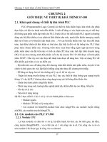
Metaxentric bush mounting (Fig. 1.18(e)) When
the bush is in the unloaded state, the steel inner
sleeve is eccentric relative to the outer one so that
Fig. 1.18 contd
22
there is more rubber on one side of it than on the
other. Precompression is applied to the rubber
expanding the inner sleeve. The bush is set so that
the greatest thickness of rubber is in compression
in the laden condition. A slot is incorporated in
the rubber on either side where the rubber is at its
minimum in such a position as to avoid stressing
any part of it in tension.
When installed, its stiffness in the fore and aft
direction is greater than in the vertical direction, the
ratio being about 2.5 : 1. This type of bush provides
a large amount of vertical deflection with very little
fore and aft movement which makes it suitable for
rear gearbox mounts using three point power unit
suspension and leaf spring eye shackle pin bushes.
Metacone sleeve mountings (Fig. 1.18(f and g))
These mounts are formed from male and female
conical sleeves, the inner male member being
centrally positioned by rubber occupying the
space between both surfaces (Fig. 1.18(f)). During
vertical vibrational deflection, the rubber between
the sleeves is subjected to a combined shear and
compression which progressively increases the stiff-
ness of the rubber as it moves towards full distor-
tion. The exposed rubber at either end overlaps the
flanged outer sleeve and there is an upper and
lower plate bolted rigidly to the ends of the inner
sleeve. These plates act as both overload (bump)
and rebound stops, so that when the inner member
deflects up or down towards the end of its move-
ment it rapidly stiffens due to the surplus rubber
being squeezed in between. Mounts of this kind are
used where stiffness is needed in the horizontal
direction with comparative freedom of movement
for vertical deflection.
An alternative version of the Metacone mount
uses a solid aluminium central cone with a flanged
pedestal conical outer steel sleeve which can be
bolted directly onto the chassis side member, see
Fig. 1.18(g). An overload plate is clamped between
the inner cone and mount support arm, but no
rebound plate is considered necessary.
These mountings are used for suspension appli-
cations such as engine to chassis, cab to chassis,
bus body and tanker tanks to chassis.
Double inclined rectangular sandwich mounting
(Fig. 1.18(h)) A pair of rectangular sandwich
rubber blocks are supported on the slopes of a
triangular pedestal. A bridging plate merges the
resilience of the inclined rubber blocks so that
they provide a combined shear and compressive
distortion within the rubber. Under small deflec-
tion conditions the shear and compression is
almost equal, but as the load and thus deflection
increases, the proportion of compression over the
shear loading predominates.
These mounts provide very good lateral stability
without impairing vertical deflection flexibility and
progressive stiffness control. When used for road
wheel axle suspension mountings, they offer good
insulation against road and other noises.
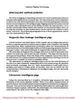
Flanged sleeve bobbin mounting with rebound
control (Fig. 1.19(a and b)) These mountings
have the rubber moulded partially around the outer
flange sleeve and in between this sleeve and an inner
tube. A central bolt attaches the inner tube to the
body structure while the outer member is bolted on
two sides to the subframe.
When loaded in the vertical downward direction,
the rubber between the sleeve and tube walls will be
in shear and the rubber on the outside of the
flanged sleeve will be in compression.
There is very little relative sideway movement
between the flanged sleeve and inner tube due to
rubber distortion. An overload plate limits the down-
ward deflection and rebound is controlled by the
lower plate and the amount and shape of rubber
trapped between it and the underside of the flanged
sleeve. A reduction of rubber between the flanged
sleeve and lower plate (Fig. 1.19(a)) reduces the
rebound, but an increase in depth of rubber increases
rebound (Fig. 1.19(b)). The load deflection charac-
teristics are given for both mounts in Fig. 1.19c.
These mountings are used extensively for body to
subframe and cab to chassis mounting points.
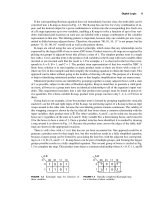
Hydroelastic engine mountings (Figs 1.20(a±c) and
1.21) A flanged steel pressing houses and sup-
ports an upper and lower rubber spring diaphragm.
The space between both diaphragms is filled and
sealed with fluid and is divided in two by a separator
plate and small transfer holes interlink the fluid
occupying these chambers (Fig. 1.20(a and b)).
Under vertical vibratory conditions the fluid will
be displaced from one chamber to the other
through transfer holes. During downward deflec-
tion (Fig. 1.20(b)), both rubber diaphragms are
subjected to a combined shear and compressive
action and some of the fluid in the upper chamber
will be pushed into the lower and back again by
way of the transfer holes when the rubber rebounds
(Fig. 1.20(a)). For low vertical vibratory frequencies,
23
the movement of fluid between the chambers is
unrestricted, but as the vibratory frequencies
increase, the transfer holes offer increasing resist-
ance to the flow of fluid and so slow down the up
and down motion of the engine support arm. This
damps and reduces the amplitude of mountings
vertical vibratory movement over a number of
cycles. A comparison of conventional rubber and
hydroelastic damping resistance over the normal
operating frequency range for engine mountings is
shown in Fig. 1.20(c).
Instead of adopting a combined rubber mount
with integral hydraulic damping, separate diagon-
ally mounted telescopic dampers may be used in
conjunction with inclined rubber mounts to reduce
both vertical and horizontal vibration (Fig. 1.21).
1.3 Fifth wheel coupling assembly
(Fig. 1.22(a and b))
The fifth wheel coupling attaches the semi-trailer to
the tractor unit. This coupling consists of a semi-
circular table plate with a central hole and a vee
section cut-out towards the rear (Fig. 1.22(b)).
Attached underneath this plate are a pair of pivot-
ing coupling jaws (Fig. 1.22(a)). The semi-trailer
has an upper fifth wheel plate welded or bolted to
the underside of its chassis at the front and in the
centre of this plate is bolted a kingpin which faces
downwards (Fig. 1.22(a)).
When the trailer is coupled to the tractor unit,
this upper plate rests and is supported on top of the
tractor fifth wheel table plate with the two halves of
the coupling jaws engaging the kingpin. To permit
Fig. 1.19 (a±c) Flanged sleeve bobbin mounting with
rebound control
24
relative swivelling between the kingpin and jaws,
the two interfaces of the tractor fifth wheel
tables and trailer upper plate should be heavily
greased. Thus, although the trailer articulates
about the kingpin, its load is carried by the tractor
table.
Flexible articulation between the tractor and
semi-trailer in the horizontal plane is achieved by
permitting the fifth wheel table to pivot on hori-
zontal trunnion bearings that lie in the same vertical
plane as the kingpin, but with their axes at right
angles to that of the tractor's wheel base (Fig.
1.22(b)). Rubber trunnion rubber bushes normally
provide longitudinal oscillations of about Æ10
.
The fifth wheel table assembly is made from
either a machined cast or forged steel sections, or
from heavy section rolled steel fabrications, and the
upper fifth wheel plate is generally hot rolled steel
welded to the trailer chassis. The coupling locking
system consisting of the jaws, pawl, pivot pins and
kingpin is produced from forged high carbon man-
ganese steels and the pressure areas of these com-
ponents are induction hardened to withstand shock
loading and wear.
1.3.1 Operation of twin jaw coupling
(Fig. 1.23(a±d))
With the trailer kingpin uncoupled, the jaws will be
in their closed position with the plunger withdrawn
from the lock gap between the rear of the jaws,
which are maintained in this position by the pawl
contacting the hold-off stop (Fig. 1.23(a)). When
coupling the tractor to the trailer, the jaws of the
Fig. 1.20 (a±c) Hydroelastic engine mount
25
fifth wheel strike the kingpin of the trailer. The
jaws are then forced open and the kingpin enters
the space between the jaws (Fig. 1.23(b)). The king-
pin contacts the rear of the jaws which then
automatically pushes them together. At the same
time, one of the coupler jaws causes the trip pin to
strike the pawl. The pawl turns on its pivot against
the force of the spring, releasing the plunger, allow-
ing it to be forced into the jaws' lock gap by its
spring (Fig. 1.23(c)). When the tractor is moving,
the drag of the kingpin increases the lateral force of
the jaws on the plunger.
To disconnect the coupling, the release hand
lever is pulled fully back (Fig. 1.23(d)). This
draws the plunger clear of the rear of the jaws
and, at the same time, allows the pawl to swing
round so that it engages a projection hold-off stop
situated at the upper end of the plunger, thus jam-
ming the plunger in the fully out position in readi-
ness for uncoupling.
1.3.2 Operation of single jaw and pawl coupling
(Fig. 1.24(a±d))
With the trailer kingpin uncoupled, the jaw will be
held open by the pawl in readiness for coupling
(Fig. 1.24(a)). When coupling the tractor to the
trailer, the jaw of the fifth wheel strikes the kingpin
of the trailer and swivels the jaw about its pivot pin
against the return spring, slightly pushing out the
pawl (Fig. 1.24(b)). Further rearward movement of
the tractor towards the trailer will swing the jaw
round until it traps and encloses the kingpin. The
spring load notched pawl will then snap over the
jaw projection to lock the kingpin in the coupling
position (Fig. 1.24(c)). The securing pin should
then be inserted through the pull lever and table
eye holes. When the tractor is driving forward, the
reaction on the kingpin increases the locking
force between the jaw projection and the notched
pawl.
To disconnect the coupling, lift out the securing
pin and pull the release hand lever fully out
(Fig. 1.24(d)). With both the tractor and trailer
stationary, the majority of the locking force
applied to notched pawl will be removed so that
with very little effort, the pawl is able to swing clear
of the jaw in readiness for uncoupling, that is, by
just driving the tractor away from the trailer. Thus
the jaw will simply swivel allowing the kingpin to
pull out and away from the jaw.
1.4 Trailer and caravan drawbar couplings
1.4.1 Eye and bolt drawbar coupling for heavy
goods trailers (Figs 1.25 and 1.26)
Drawbar trailers are normally hitched to the truck
by means of an `A' frame drawbar which is coupled
by means of a towing eye formed on the end of the
drawbar (Fig. 1.25). When coupled, the towing eye
hole is aligned with the vertical holes in the upper
and lower jaws of the truck coupling and an eye
bolt passes through both coupling jaws and draw-
bar eye to complete the attachment (Fig. 1.26).
Lateral drawbar swing is permitted owing to the
eye bolt pivoting action and the slots between the
Fig. 1.21 Diagonally mounted hydraulic dampers suppress both vertical and horizontal vibrations
26
jaws on either side. Aligning the towing eye to the
jaws is made easier by the converging upper and
lower lips of the jaws which guide the towing eye as
the truck is reversed and the jaws approach the
drawbar. Isolating the coupling jaws from the
truck draw beam are two rubber blocks which act
as a damping media between the towing vehicle and
trailer. These rubber blocks also permit additional
deflection of the coupling jaw shaft relative to the
draw beam under rough abnormal operating con-
ditions, thus preventing over-straining the drawbar
and chassis system.
Fig. 1.22 (a and b) Fifth wheel coupling assembly
27
Fig. 1.23 (a±d) Fifth wheel coupling with twin jaws plunger and pawl
28
Fig. 1.24 (a±d) Fifth wheel coupling with single jaw and pawl
29
The coupling jaws, eye bolt and towing eye are
generally made from forged manganese steel with
induction hardened pressure areas to increase the
wear resistance.
Operation of the automatic drawbar coupling
(Fig. 1.26) In the uncoupled position the eyebolt
is held in the open position ready for coupling
(Fig. 1.26(a)). When the truck is reversed, the jaws
of the coupling slip over the towing eye and in the
process strike the conical lower end of the eye bolt
(Fig. 1.26(b)). Subsequently, the eye bolt will lift. This
trips the spring-loaded wedge lever which now rotates
clockwise so that it bears down on the eye bolt.
Further inward movement of the eye bolt between
the coupling jaws aligns the towing eye with the eye
bolt. The spring pressure now acts through the wedge
lever to push the eye bolt through the towing eye and
the lower coupling jaw (Fig. 1.26(c)). When the eye
bolt stop-plate has been fully lowered by the spring
tension, the wedge lever will slot into its groove
formed in the centre of the eye bolt so that it locks
the eye bolt in the coupled position.
To uncouple the drawbar, the handle is pulled
upwards against the tension of the coil spring
mounted on the wedge level operating shaft
(Fig. 1.26(d)). This unlocks the wedge, freeing the
eyebolt and then raises the eye bolt to the
uncoupled position where the wedge lever jams it
in the open position (Fig. 1.26(a)).
1.4.2 Ball and socket towing bar coupling for
light caravan/trailers (Fig. 1.27)
Light trailers or caravans are usually attached to
the rear of the towing car by means of a ball and
socket type coupling. The ball part of the attach-
ment is bolted onto a bracing bracket fitted directly
to the boot pan or the towing load may be shared
out between two side brackets attached to the rear
longitudinal box-section members of the body.
A single channel section or pair of triangularly
arranged angle-section arms may be used to form
the towbar which both supports and draws the
trailer.
Attached to the end of the towbar is the socket
housing with an internally formed spherical cavity.
This fits over the ball member of the coupling so
that it forms a pivot joint which can operate in both
the horizontal and vertical plane (Fig. 1.27).
To secure the socket over the ball, a lock device
must be incorporated which enables the coupling to
be readily connected or disconnected. This lock
may take the form of a spring-loaded horizontally
positioned wedge with a groove formed across its
top face which slips underneath and against the
ball. The wedge is held in the closed engaged pos-
ition by a spring-loaded vertical plunger which has
a horizontal groove cut on one side. An uncoupling
lever engages the plunger's groove so that when the
coupling is disconnected the lever is squeezed to lift
and release the plunger from the wedge. At the
same time the whole towbar is raised by the handle
to clear the socket and from the ball member.
Coupling the tow bar to the car simply reverses
the process, the uncoupling lever is again squeezed
against the handle to withdraw the plunger and the
socket housing is pushed down over the ball mem-
ber. The wedge moves outwards and allows the ball
to enter the socket and immediately the wedge
springs back into the engaged position. Releasing
the lever and handle completes the coupling by
permitting the plunger to enter the wedge lock
groove.
Sometimes a strong compression spring is inter-
posed between the socket housing member and the
towing (draw) bar to cushion the shock load when
the car/trailer combination is initially driven away
from a standstill.
1.5 Semi-trailer landing gear (Fig. 1.28)
Landing legs are used to support the front of the
semi-trailer when the tractor unit is uncoupled.
Extendable landing legs are bolted vertically to
each chassis side-member behind the rear wheels of
Fig. 1.25 Drawbar trailer
30
Fig. 1.26 (a±e) Automatic drawbar coupling
31
the tractor unit, just sufficiently back to clear the
rear tractor road wheels when the trailer is coupled
and the combination is being manoeuvred
(Fig. 1.28(a)). To provide additional support for
the legs, bracing stays are attached between the legs
and from the legs diagonally to the chassis cross-
member (Fig. 1.28(b)).
The legs consist of inner and outer high tensile
steel tubes of square section. A jackscrew with a
bevel wheel attached at its top end supported by the
outer leg horizontal plate in a bronze bush bearing.
The jawscrew fits into a nut which is mounted at
the top of the inner leg and a taper roller bearing
race is placed underneath the outer leg horizontal
support plate and the upper part of the jackscrew
to minimize friction when the screw is rotated (Fig.
1.28(b)). The bottom ends of the inner legs may
support either twin wheels, which enable the trailer
to be manoeuvred, or simply flat feet. The latter are
able to spread the load and so permit greater load
capacity.
To extend or retract the inner legs, a winding
handle is attached to either the low or high speed
shaft protruding from the side of the gearbox. The
upper high speed shaft supports a bevel pinion
which meshes with a vertically mounted bevel
wheel forming part of the jackscrew.
Rotating the upper shaft imparts motion directly
to the jackscrew through the bevel gears. If greater
leverage is required to raise or lower the front of the
trailer, the lower shaft is engaged and rotated.
This provides a gear reduction through a com-
pound gear train to the upper shaft which then
drives the bevel pinion and wheel and hence the
jackscrew.
1.6 Automatic chassis lubrication system
1.6.1 The need for automatic lubrication system
(Fig. 1.29)
Owing to the heavy loads they carry commercial
vehicles still prefer to use metal to metal joints which
are externally lubricated. Such joints are kingpins
and bushes, shackle pins and bushes, steering ball
joints, fifth wheel coupling, parking brake linkage
etc. (Fig. 1.29). These joints require lubricating in
proportion to the amount of relative movement and
the loads exerted. If lubrication is to be effective in
reducing wear between the moving parts, fresh oil
must be pumped between the joints frequently. This
can best be achieved by incorporating an automatic
lubrication system which pumps oil to the bearing's
surfaces in accordance to the distance travelled by
the vehicle.
1.6.2 Description of airdromic automatic chassis
lubrication system (Fig. 1.30)
This lubrication system comprises four major com-
ponents; a combined pump assembly, a power unit,
an oil unloader valve and an air control unit.
Pump assembly (Fig. 1.30) The pump assembly
consists of a circular housing containing a ratchet
operated drive (cam) shaft upon which are
mounted one, two or three single lobe cams (only
one cam shown). Each cam operates a row of 20
pumping units disposed radially around the pump
casing, the units being connected to the chassis
bearings by nylon tubing.
Power unit (Fig. 1.30) This unit comprises a
cylinder and spring-loaded air operated piston
which is mounted on the front face of the pump
assembly housing, the piston rod being connected
indirectly to the drive shaft ratchet wheel by way of
a ratchet housing and pawl.
Oil unloader valve (Fig. 1.30) This consists of a
shuttle valve mounted on the front of the pump
assembly housing. The oil unloader valve allows air
pressure to flow to the power unit for the power
stroke. During the exhaust stroke, however, when
air flow is reversed and the shuttle valve is lifted
from its seat, any oil in the line between the power
unit and the oil unloader valve is then discharged to
atmosphere.
Fig. 1.27 Ball and socket caravan/trailer towing
attachment
32
Fig. 1.28 (a and b) Semi-trailer landing gear
33
Air control unit (Fig. 1.30) This unit is mounted
on the gearbox and is driven via the speedometer
take-off point. It consists of a worm and wheel drive
which operates an air proportioning control
unit. This air proportioning unit is operated by a
single lift face cam which actuates two poppet
valves, one controlling air supply to the power
unit, the other controlling the exhaust air from the
power unit.
1.6.3 Operation of airdromic automatic chassis
lubrication system (Fig. 1.30)
Air from the air brake auxiliary reservoir passes by
way of the safety valve to the air control (propor-
tioning) unit inlet valve. Whilst the inlet valve is
held open by the continuously rotating face cam
lobe, air pressure is supplied via the oil unloader
valve to the power unit attached to the multipump
assembly housing. The power unit cylinder is sup-
ported by a pivot to the pump assembly casing,
whilst the piston is linked to the ratchet and pawl
housing. Because the pawl meshes with one of the
ratchet teeth and the ratchet wheel forms part of
the camshaft, air pressure in the power cylinder will
partially rotate both the ratchet and pawl housing
and the camshaft clockwise. The cam (or cams) are
in contact with one or more pump unit, and so each
partial rotation contributes to a proportion of the
jerk plunger and barrel pumping cycle of each unit
(Fig. 1.30).
As the control unit face cam continues to rotate,
the inlet poppet inlet valve is closed and the exhaust
poppet valve opens. Compressed air in the air con-
trol unit and above the oil control shuttle valve will
now escape through the air control unit exhaust
port to the atmosphere. Consequently the com-
pressed air underneath the oil unloader shuttle
valve will be able to lift it and any trapped air and
oil in the power cylinder will now be released via
the hole under the exhaust port. The power unit
piston will be returned to its innermost position by
the spring and in doing so will rotate the ratchet
and pawl housing anti-clockwise. The pawl is thus
Fig. 1.29 Tractor unit automatic lubrication system
34
Fig. 1.30 Airdromic automatic chassis lubrication system
35
able to slip over one or more of the ratchet teeth to
take up a new position. The net result of the power
cylinder being charged and discharged with com-
pressed air is a slow but progressive rotation of the
camshaft (Fig. 1.30).
A typical worm drive shaft to distance travelled
relationship is 500 revolutions per 1 km. For 900
worm drive shaft revolutions the pumping cam
revolves once. Therefore, every chassis lubrication
point will receive one shot of lubricant in this
distance.
When the individual lubrication pump unit's
primary plunger is in its outermost position, oil
surrounding the barrel will enter the inlet port,
filling the space between the two plungers. As the
cam rotates and the lobe lifts the primary plunger,
it cuts off the inlet port. Further plunger rise will
partially push out the secondary plunger and so
open the check valve. Pressurised oil will then
pass between the loose fitting secondary plunger
and barrel to lubricate the chassis moving part it
services (Fig. 1.30).
36
2 Friction clutch
2.1 Clutch fundamentals
Clutches are designed to engage and disengage the
transmission system from the engine when a vehicle
is being driven away from a standstill and when the
gearbox gear changes are necessary. The gradual
increase in the transfer of engine torque to the
transmission must be smooth. Once the vehicle is
in motion, separation and take-up of the drive for
gear selection must be carried out rapidly without
any fierceness, snatch or shock.
2.1.1 Driven plate inertia
To enable the clutch to be operated effectively, the
driven plate must be as light as possible so that
when the clutch is disengaged, it will have the mini-
mum of spin, i.e. very little flywheel effect. Spin
prevention is of the utmost importance if the vari-
ous pairs of dog teeth of the gearbox gears, be they
constant mesh or synchromesh, are to align in the
shortest time without causing excessive pressure,
wear and noise between the initial chamfer of the
dog teeth during the engagement phase.
Smoothness of clutch engagement may be
achieved by building into the driven plate some
sort of cushioning device, which will be discussed
later in the chapter, whilst rapid slowing down of
the driven plate is obtained by keeping the diameter,
centre of gravity and weight of the driven plate to
the minimum for a given torque carrying capacity.
2.1.2 Driven plate transmitted torque capacity
The torque capacity of a friction clutch can be
raised by increasing the coefficient of friction of
the rubbing materials, the diameter and/or the
spring thrust sandwiching the driven plate. The
friction lining materials now available limit the
coefficient of friction to something of the order of
0.35. There are materials which have higher coeffi-
cient of friction values, but these tend to be
unstable and to snatch during take-up. Increasing
the diameter of the driven plate unfortunately
raises its inertia, its tendency to continue spinning
when the driven plate is freed while the clutch is in
the disengaged position, and there is also a limit to
the clamping pressure to which the friction lining
material may be subjected if it is to maintain its
friction properties over a long period of time.
2.1.3 Multi-pairs of rubbing surfaces (Fig. 2.1)
An alternative approach to raising the transmitted
torque capacity of the clutch is to increase the
number of pairs of rubbing surfaces. Theoretically
the torque capacity of a clutch is directly propor-
tional to the number of pairs of surfaces for a given
clamping load. Thus the conventional single driven
plate has two pairs of friction faces so that a twin
or triple driven plate clutch for the same spring
thrust would ideally have twice or three times the
torque transmitting capacity respectively of that of
the single driven plate unit (Fig. 2.1). However,
because it is very difficult to dissipate the extra
heat generated in a clutch unit, a larger safety factor
is necessary per driven plate so that the torque
capacity is generally only of the order 80% per pair
of surfaces relative to the single driven plate clutch.
2.1.4 Driven plate wear (Fig. 2.1)
Lining life is also improved by increasing the
number of pairs of rubbing surfaces because wear
is directly related to the energy dissipation per unit
area of contact surface. Ideally, by doubling the
surface area as in a twin plate clutch, the energy
input per unit lining area will be halved for a given
slip time which would result in a 50% decrease in
facing wear. In practice, however, this rarely occurs
(Fig. 2.1) as the wear rate is also greatly influenced
by the peak surface rubbing temperature and the
intermediate plate of a twin plate clutch operates at
a higher working temperature than either the fly-
wheel or pressure plate which can be more effect-
ively cooled. Thus in a twin plate clutch, half the
energy generated whilst slipping must be absorbed
by the intermediate plate and only a quarter each
by the flywheel and pressure plate. This is usually
borne out by the appearance of the intermediate
plate and its corresponding lining faces showing
evidence of high temperatures and increased wear
compared to the linings facing the flywheel and
pressure plate. Nevertheless, multiplate clutches
do have a life expectancy which is more or less
related to the number of pairs of friction faces for
a given diameter of clutch.
For heavy duty applications such as those
required for large trucks, twin driven plates are
used, while for high performance cars where very
37
rapid gear changes are necessary and large
amounts of power are to be developed, small
diameter multiplate clutches are preferred.
2.2 Angular driven plate cushioning and torsional
damping (Figs 2.2±2.8)
2.2.1 Axial driven plate friction lining cushioning
(Figs 2.2, 2.3 and 2.4)
In its simplest form the driven plate consists of
a central splined hub. Mounted on this hub is a
thin steel disc which in turn supports, by means of
a ring of rivets, both halves of the annular friction
linings (Figs 2.2 and 2.3).
Axial cushioning between the friction lining
faces may be achieved by forming a series of evenly
spaced `T' slots around the outer rim of the disc.
This then divides the rim into a number of seg-
ments (Arcuate) (Fig. 2.4(a)). A horseshoe shape
is further punched out of each segment. The central
portion or blade of each horseshoe is given a per-
manent set to one side and consecutive segments
have opposite sets so that every second segment is
riveted to the same friction lining. The alternative
set of these central blades formed by the horseshoe
punch-out spreads the two half friction linings apart.
An improved version uses separately attached, very
thin spring steel segments (borglite) (Fig. 2.4(b)), pos-
itioned end-on around a slightly thicker disc plate.
These segments are provided with a wavy `set' so as
to distance the two half annular friction linings.
Both forms of crimped spring steel segments
situated between the friction linings provide
Fig. 2.1 Relationship of torque capacity wear rate and pairs of rubbing faces for multiplate clutch
Fig. 2.2 Clutch driven centre plate (pictorial view)
38
progressive take-up over a greater pedal travel and
prevent snatch. The separately attached spring
segments are thinner than the segments formed out
of the single piece driven plate, so that the squeeze
take-up is generally softer and the spin inertia of the
thinner segments is noticeably reduced.
A further benefit created by the spring segments
ensures satisfactory bedding of the facing material
and a more even distribution of the work load. In
addition, cooling between the friction linings occurs
when the clutch is disengaged which helps to sta-
bilise the frictional properties of the face material.
The advantages of axial cushioning of the face
linings provide the following:
a) Better clutch engagement control, allowing
lower engine speeds to be used at take-up thus
prolonging the life of the friction faces.
b) Improved distribution of the friction work over
the lining faces reduces peak operating tempera-
tures and prevents lining fade, with the resulting
reduction in coefficient of friction and subse-
quent clutch slip.
The spring take-up characteristics of the driven
plate are such that when the clutch is initially
engaged, the segments are progressively flattened so
that the rate of increase in clamping load is provided
by the rate of reaction offered by the spring
segments (Fig. 2.5). This first low rate take-up
period is followed by a second high rate engage-
ment, caused by the effects of the pressure plate
springs exerting their clamping thrust as they are
allowed to expand against the pressure plate and
so sandwich the friction lining between the flywheel
and pressure plate faces.
2.2.2 Torsional damping of driven plate
Crankshaft torsional vibration (Fig. 2.6) Engine
crankshafts are subjected to torsional wind-up
and vibration at certain speeds due to the power
impulses. Superimposed onto some steady mean
rotational speed of the crankshaft will be additional
fluctuating torques which will accelerate and decel-
erate the crankshaft, particularly at the front pulley
Fig. 2.3 Clutch driven centre plate (sectional view)
Fig. 2.4 (a and b) Driven plate cushion take-up
39
end and to a lesser extent the rear flywheel end
(Fig. 2.6). If the flywheel end of the crankshaft
were allowed to twist in one direction and then the
other while rotating at certain critical speeds, the
oscillating angular movements would take up the
backlash between meshing gear teeth in the transmis-
sion system. Consequently, the teeth of the driving
gears would be moving between the drive (pressure
side) and non-drive tooth profiles of the driven gears.
This would result in repeated shockloads imposed on
the gear teeth, wear, and noise in the form of
gear clatter. To overcome the effects of crankshaft
torsional vibrations a torsion damping device is
normally incorporated within the driven plate hub
assembly which will now be described and explained.
Construction and operation of torsional damper
springs (Figs 2.2, 2.3 and 2.7) To transmit torque
more smoothly and progressively during take-up of
normal driving and to reduce torsional oscillations
being transmitted from the crankshaft to the trans-
mission, compressed springs are generally arranged
circumferentially around the hub of the driven
plate (Figs 2.2 and 2.3). These springs are inserted
in elongated slots formed in both the flange of the
splined hub and the side plates which enclose the
hub's flange (Fig. 2.3). These side plates are riveted
together by either three or six rivet posts which pass
through the flanged hub limit slots. This thus
provides a degree of relative angular movement
between hub and side plates. The ends of the helical
coil springs bear against both central hub flange
and the side plates. Engine torque is therefore
transmitted from the friction face linings and side
plates through the springs to the hub flange, so that
any fluctuation of torque will cause the springs to
compress and rebound accordingly.
Multistage driven plate torsional spring dampers
may be incorporated by using a range of different
springs having various stiffnesses and spring loca-
tion slots of different lengths to produce a variety
of parabolic torsional load±deflection characteris-
tics (Fig. 2.7) to suit specific vehicle applications.
The amount of torsional deflection necessary
varies for each particular application. For example,
with a front mounted engine and rear wheel drive
vehicle, a moderate driven plate angular movement
is necessary, say six degrees, since the normal trans-
mission elastic wind-up is almost adequate, but with
an integral engine, gearbox and final drive arrange-
ment, the short transmission drive length necessit-
ates considerably more relative angular deflection,
say twelve degrees, within the driven plate hub
assembly to produce the same quality of take-up.
Construction and operation of torsional damper
washers (Figs 2.2, 2.3 and 2.8) The torsional
energy created by the oscillating crankshaft is
partially absorbed and damped by the friction
washer clutch situated on either side of the hub
flange (Figs 2.2 and 2.3). Axial damping load is
achieved by a Belleville dished washer spring
mounted between one of the side plates and a four
lug thrust washer.
Fig. 2.5 Characteristics of driven plate axial clamping
load to deflection take-up
Fig. 2.6 Characteristics of crankshaft torsional
vibrations undamped and damped
40
The outer diameter of this dished spring presses
against the side plate and the inner diameter pushes
onto the lugged thrust washer. In its free state
the Belleville spring is conical in shape but when
assembled it is compressed almost flat. As the fric-
tion washers wear, the dished spring cone angle
increases. This exerts a greater axial thrust, but
since the distance between the side plate and lugged
thrust washer has increased, the resultant clamping
thrust remains almost constant (Fig. 2.8).
2.3 Clutch friction materials
Clutch friction linings or buttons are subjected to
severe rubbing and generation of heat for relatively
short periods. Therefore it is desirable that they
have a combination of these properties:
a) Relatively high coefficient of friction under
operating conditions,
b) capability of maintaining friction properties
over its working life,
c) relatively high energy absorption capacity for
short periods,
d) capability of withstanding high pressure plate
compressive loads,
e) capability of withstanding bursts of centrifugal
force when gear changing,
f) adequate shear strength to transmit engine
torque,
g) high level of cyclic working endurance without
the deterioration in friction properties,
h) good compatibility with cast iron facings over
the normal operating temperature range,
i) a high degree of interface contamination toler-
ance without affecting its friction take-up and
grip characteristics.
2.3.1 Asbestos-based linings (Figs 2.2 and 2.3)
Generally, clutch driven plate asbestos-based lin-
ings are of the woven variety. These woven linings
are made from asbestos fibre spun around lengths
of brass or zinc wire to make lengths of threads
which are both heat resistant and strong. The
woven cloth can be processed in one of two ways:
a) The fibre wire thread is woven into a cloth and
pressed out into discs of the required diameter,
followed by stitching several of these discs
together to obtain the desired thickness. The
resultant disc is then dipped into resin to bond
the woven asbestos threads together.
b) The asbestos fibre wire is woven in three dimen-
sions in the form of a disc to obtain in a single
stage the desired thickness. It is then pressed
into shape and bonded together by again dip-
ping it into a resin solution. Finally, the rigid
lining is machined and drilled ready for riveting
to the driven plate.
Development in weaving techniques has, in
certain cases, eliminated the use of wire coring so
that asbestos woven lining may be offered as either
non- or semi-metallic to match a variety of working
conditions.
Asbestos is a condensate produced by the solidi-
fication of rock masses which cool at differential
Fig. 2.7 Characteristics of driven plate torsional spring
torques to deflection take-up
Fig. 2.8 Characteristics of driven plate torsional
damper thrust spring
41