Tài liệu U.S.Sensor P2 docx
Bạn đang xem bản rút gọn của tài liệu. Xem và tải ngay bản đầy đủ của tài liệu tại đây (2.08 MB, 20 trang )
Surface Mount
End-Banded Chip Thermistors
0805 and 1206 Style
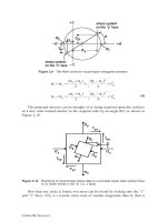
U.S. Sensor’s surface mount end-banded thermistor elements are
designed for use on hybrid substrates, integrated circuits or printed
circuit boards. They have a solder coated metallization which is suitable
for various contact techniques including wire bond, epoxy or solder.
Since they are manufactured using the most advanced equipment and
technology available, their dimensional parameters are extremely uniform
making the devices especially suitable for use with automatic handling
and placement equipment.
“LR” SERIES
0.120"
± 0.010"
0.050"
MAX
Features
• Surface mountable
• Small size
• Low cost
• Rated to 150˚C operating temperature
0.060" ±0.010"
0.008"
MIN
Options
• Non-standard resistance values and tolerances
• Special electrode materials
• Special dimensions
• Tape and reel packaging
• Solder coated metallization
SOLDER COATED "LB-2000" LEACH
RESISTANT TERMINATIONS (TYP)
“KR” SERIES
THICKNESS:
0.055" MAX
0.079"
± 0.008"
Specifications
• Thermal time constant: 10 seconds max.
• Dissipation constant: 1 mW/˚C
0.049" ± 0.008"
0.008" MIN
SOLDER COATED “LB-2000” LEACH
RESISTANT TERMINATIONS (TYP)
Surface Mount End-Banded Chip Thermistors
Part Number
0805 Series
KR102B1K
KR252B1K
KR502F1K
KR103F1K
KR203F1K
KR303J1K
KR503J1K
KR753J1K
KR104J1K
Part Number
1206 Series
Resistance
Ω @ 25˚C
LR102B1K
LR252B1K
LR502F1K
LR103F1K
LR203F1K
LR303J1K
LR503J1K
LR753J1K
LR104J1K
1000
2500
5000
10000
20000
30000
50000
75000
100000
*Resistance
Tol. ± %
R-T Curve
(See Pg. 44-45)
10
10
10
10
10
10
10
10
10
B
B
F
F
F
J
J
J
J
Beta (˚K)
0-50˚C
2930
2930
3420
3420
3420
3890
3890
3890
3890
*Resistance tolerances of ±5%, 20% are available upon request
20
1832 West Collins Avenue, Orange, CA 92867 • Tel. (714) 639-1000 • Fax (714) 639-1220 • www.ussensor.com
Leadless
Top/Bottom Terminated Chip Thermistors
U.S. Sensor’s leadless chip thermistor elements are designed for use on
hybrid substrates, integrated circuits or printed circuit boards. They
have silver metallization on their top and bottom which is suitable for
various contact techniques including wire bond, epoxy or solder. Since
they are manufactured using the most advanced equipment and technology available, their dimensional parameters are extremely uniform,
making the devices especially suitable for use with automatic handling
and placement equipment.
Features
• Surface mountable
• Small size
• Very low profile
• Low cost
• Rapid response time
• Rated to 150˚C
L
W
SILVER METALLIZATION
TOP AND BOTTOM
Options
• Non-standard resistance values and tolerances
• Special electrode materials (silver or gold)
• Special dimensions
• Tape and reel packaging
T
(THICKNESS)
Specifications
• Thermal time constant: 2 seconds max.
• Dissipation constant: 1mW/˚C
Leadless Chip Thermistors
Part
Number
Resistance *Resistance
R-T Curve
Beta (˚K)
Ω @ 25˚C
Tol. ± % (See Pg. 44-45) 0-50˚C
Nominal Dimensions (Inches)
Dim. “L” Dim.“W” Dim. “T”
BC101B1K
BC501F1K
BC102F1K
100
500
1000
10
10
10
B
F
F
2930
3420
3420
0.060
0.075
0.045
0.060
0.075
0.045
0.015
0.015
0.015
BC222J1K
BC302J1K
BC502J1K
2252
3000
5000
10
10
10
J
J
J
3890
3890
3890
0.070
0.065
0.055
0.070
0.065
0.055
0.010
0.010
0.015
BC103J1K
BC203J1K
BC303J1K
10000
20000
30000
10
10
10
J
J
J
3890
3890
3890
0.040
0.030
0.025
0.040
0.030
0.025
0.015
0.015
0.020
BC503J1K
BC104R!K
50000
100000
10
10
J
R
3890
4140
0.020
0.022
0.020
0.022
0.020
0.016
21
1832 West Collins Avenue, Orange, CA 92867 • Tel. (714) 639-1000 • Fax (714) 639-1220 • www.ussensor.com
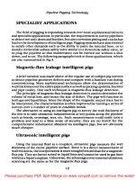
Inrush Current Limiting
Power Thermistors
U.S. Sensor’s inrush current limiting power thermistors are specially formulated
and processed NTC thermistors suitable for suppressing high inrush currents in
switching power supplies and other applications where the high initial starting
currents are undesirable. Their unique design enables them to handle extremely
high current and voltage levels. In a typical power supply application, the device
is used in series with the filter capacitors. Upon application of the initial voltage,
the device, due to its relatively high resistance, limits the current flow to an
acceptable level until the capacitors are charged. Thereafter, the device decreases
in resistance substantially to a level where the voltage drop across it is negligible.
Maximum Steady State Current (Imax)
For power thermistors, the maximum continuous
steady state current, either DC or RMS AC, which
the device is capable of passing. The maximum
steady state current for U.S. Sensor power thermistors is determined assuming a maximum operating
ambient temperature of 65˚C. If a specific application requires ambient temperature operation above
65˚C, custom designed devices are available.
T
1.0" MIN
D
0.310" NOM
TINNED SOLDERABLE WIRE
SEE CHART FOR LEAD DIAMETER
PROTECTIVE COATING
Resistance At Maximum Current (RImax)
For power thermistors, the approximate resistance of the
device under maximum steady state current conditions.
Inrush Current Limiting Power Thermistors
Part
Number
Imax
R0 Resistance
@ 25˚C
Max. Steady State
± 20% Ω
Current (Amps)
RImax Resis.
@ Max.
Current Ω
Dim. “D” Dim. “T” Lead Dia.
(Max. Over (Max. Over (Nom.)
Coating)
Coating)
ST1R020B
ST1R030B
ST2R018B
1.0
1.0
2.0
20
30
18
0.015
0.015
0.030
0.900”
1.250”
0.900"
0.300”
0.250”
0350"
0.040”
0.040”
0.040"
ST2R503B
ST2R507B
ST2R509B
2.5
2.5
2.5
3
7
9
0.150
0.050
0.040
0.600"
0.600"
0.600"
0.250"
0.250"
0.250"
0.032"
0.032"
0.032"
ST2R510B
ST2R515B
ST5R002B
2.5
2.5
5.0
10
15
2
0.040
0.030
0.400
0.900"
0.900"
0.600"
0.300"
0.300"
0.250"
0.040"
0.040"
0.032"
ST5R005B
ST5R007B
ST7R004B
5.0
5.0
7.0
5
7
4
0.100
0.070
0.200
0.600"
0.600"
0.600"
0.250"
0.250"
0.300"
0.032"
0.032"
0.040"
ST10003B
ST10005B
ST10006B
10.0
10.0
10.0
3
5
6
0.200
0.200
0.150
0.450"
0.600"
0.600"
0.300"
0.350"
0.350"
0.032"
0.040"
0.040"
ST10010B
ST20002B
ST40002B
10.0
20.0
40.0
10
2
2
0.100
0.600
0.600
1.250”
0.500"
0.625"
0.300”
0.300"
0.250"
0.040”
0.032"
0.032"
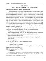
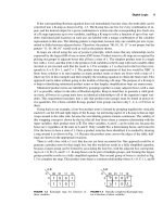
The circuit diagram above
demonstrates a typical method to
limit inrush current at turn on in
a power supply. Two or more
inrush current limiting devices
may be used in series or in separate legs of the supply circuit.
The devices may not be used in
parallel since one will tend to
pass nearly all the current available. U.S. Sensor’s inrush current
limiters may be used in either the
AC or DC portions of the circuit.
22
1832 West Collins Avenue, Orange, CA 92867 • Tel. (714) 639-1000 • Fax (714) 639-1220 • www.ussensor.com
Thin Film
Platinum RTD’s
U.S. Sensor’s thin film platinum resistance temperature detectors (PtRTD) consist of a thin film platinum deposited on a ceramic substrate.
Thin film Pt-RTD’s provide cost advantages when compared to wire
wound Pt-RTD’s because of their lower material cost factor.
Features
• Glass coated platinum element
• Virtually linear relationship between temperature and resistance
• Capable of withstanding temperatures ranging from -50˚C to +500˚C.
Higher temperature ratings are available by special order
• High accuracy: Resistance and temperature
deviation can be controlled to within ±0.06% and
±0.15˚C, a tolerance that corresponds to Class “A” of
IEC 751 or 1/2 DIN of DIN 43760
• High Reliability: Capable of withstanding extreme
environmental conditions
• Available in various probe configurations for specific
applications
• Excellent stability even at high temperatures
Specifications
• Thermal time constant: 15 seconds max. (moving air)
• Dissipation constant: 2 mW/˚C (moving air)
• Maximum applied current: 1 mA
Thin Film Platinum RTD Elements
Part
Number
PPG101A1
PPG101B1
PPG101C1
PPG101D1
PPG501A1
PPG501B1
PPG501C1
PPG501D1
PPG102A1
PPG102B1
PPG102C1
PPG102D1
PPG102A2
PPG102B2
PPG102C2
PPG102D2
Resistance
Ω @ 0˚C
100
100
100
100
500
500
500
500
1000
1000
1000
1000
1000
1000
1000
1000
DIN 43760
Class
Resistance
Tol. ± % @ 0˚C
A
B
C
D
A
B
C
D
A
B
C
D
A
B
C
D
0.06
0.12
0.24
0.48
0.06
0.12
0.24
0.48
0.06
0.12
0.24
0.48
0.06
0.12
0.24
0.48
Temp.
Dev. ±˚C @ 0˚C
0.15
0.30
0.60
1.20
0.15
0.30
0.60
1.20
0.15
0.30
0.60
1.20
0.15
0.30
0.60
1.20
TCR
ppm/˚C
Dim “W”
(± 0.007”)
3850
3850
3850
3850
3850
3850
3850
3850
3850
3850
3850
3850
3750
3750
3750
3750
0.067”
0.067”
0.067”
0.067”
0.079”
0.079”
0.079”
0.079”
0.079”
0.079”
0.079”
0.079”
0.079”
0.079”
0.079”
0.079”
Dim “L”
(± 0.008”)
0.095”
0.095”
0.095”
0.095”
0.118”
0.118”
0.118”
0.118”
0.118”
0.118”
0.118”
0.118”
0.118”
0.118”
0.118”
0.118”
23
1832 West Collins Avenue, Orange, CA 92867 • Tel. (714) 639-1000 • Fax (714) 639-1220 • www.ussensor.com
Calibrated
Thermistor Probes
U.S. Sensor’s calibrated thermistor probes are manufactured with ultra
high stability thermistor elements. This low cost high accuracy probe is
provided with a NIST traceable calibration certificate with data points
and a Resistance vs. Temperature (R/T) chart in 0.01˚C increments.
The ultra high stability, precision, cost, and inherent ruggedness of this
thermistor probe make it an excellent temperature standard for applications ranging from the metrology laboratory to the factory floor.
Features
• Excellent long term stability
• High accuracy
• Durable
• Low Cost
• NIST Traceability
9.50" ± 0.500"
“L2”
0.250" ± 0.005"
Options
• Custom temperature ranges
• Probe lengths and styles
• Fahrenheit calibration certificate
STRIP:
0.250" ± 0.070"
LEAD WIRE:
24 AWG, TWO CONDUCTOR,
STRANDED CONDUCTOR,
PVC INSULATED ZIPCORD
THERMISTOR ELEMENT POTTED
NEAR TIP OF 300 SERIES
STAINLESS STEEL PROBE HOUSING
Specifications
• Accuracy: ±0.01˚C
• Typical Drift: less than 0.01˚C per year
Calibrated Thermistor Probes
Part
Number
USP3021
USP3986
Nominal
Resistance Ω @ 25˚C
10,000
100,000
Accuracy
Temperature
Range
0.01˚C
0.01˚C
-20˚C to +70˚C
0 to +105˚C
24
1832 West Collins Avenue, Orange, CA 92867 • Tel. (714) 639-1000 • Fax (714) 639-1220 • www.ussensor.com
U.S. Sensor manufactures an extensive line of thermistor and
RTD probes designed to meet the most demanding environmental applications. In most cases, the probe housings are
available with various probe lengths as well as with a wide
selection of lead wire materials and terminations.
25
U.S. Sensor has automated equipment for attaching all major
brands of wire terminals and connector housings. The photo
below shows just a small sampling of our capabilities. Please
contact U.S. Sensor’s application engineering department for
assistance in selecting the wire terminations for your
application.
26
1832 West Collins Avenue, Orange, CA 92867 • Tel. (714) 639-1000 • Fax (714) 639-1220 • www.ussensor.com
H2081
NPT Stainless Steel
“L2”
“L1”
“D”
STRIP: 0.250" ± 0.070"
NPT THREAD SIZES
AVAILABLE:
1/8"
1/4"
3/8"
1/2"
3/4"
H3475
1/8" NPT Brass
0.560"
± 0.035"
“L2”
0.4375"
± 0.035"
HEX
H2998
DIM “D”:
1/8" (0.125")
3/16" (0.188")
1/4" (0.250")
STRIP: 0.250" ± 0.070"
0.200"
± 0.025"
THERMISTOR ELEMENT
POTTED IN
BRASS PIPE PLUG
1/8" - 27
NPT THREAD
(RHT)
1/4" NPT Brass
“L2”
0.880"
± 0.015"
0.650"
± 0.050"
0.250" ± 0.010"
0.562"
± 0.035"
HEX
H3476
STRIP: 0.250" ± 0.070"
0.250"
± 0.020"
1/4" - 18
NPT THREAD
(RHT)
SENSOR ELEMENT POTTED
NEAR TIP OF BRASS HOUSING
1/4" NPT Brass
“L2”
0.562"
± 0.030"
HEX
0.740"
± 0.035"
THERMISTOR ELEMENT
POTTED IN
BRASS PIPE PLUG
STRIP: 0.250" ± 0.070"
0.190"
± 0.020
1/4" - 18
NPT THREAD
(RHT)
Dimensions “L1” “L2” and “D” are user
,
selectable. Contact U.S. Sensor’s application engineering department to design a
probe assembly to best suit your use.
27
THERMISTOR and RTD PROBE ASSEMBLIES
1832 West Collins Avenue, Orange, CA 92867 • Tel. (714) 639-1000 • Fax (714) 639-1220 • www.ussensor.com
H1060
Stainless Steel, round flange
2 #6 SCREW
MTG. HOLES
1.5"
± 0.05"
“L2”
STRAIN
RELIEF
STAINLESS STEEL
0.250"
NOM
0.125"
0.037"
0.750"
THERMISTOR POTTED
IN TIP
H3535
1.0"
± 0.010"
Stainless Steel, round flange
0.032"
± 0.008"
0.145" ± 0.010"
#6 STUD SIZE
MOUNTING HOLES
2.250" ± 0.250"
“L2”
0.314" ± 0.010"
DIAMETER
STRIP:
0.250" ± 0.070"
NICKEL PLATED
STEEL MOUNTING
FLANGE
H3783
0.400"
± 0.035"
0.250"
± 0.005"
SENSOR ELEMENT POTTED
NEAR CLOSED TIP OF 300 SERIES
STAINLESS STEEL TUBE
0.815"
± 0.015"
Stainless Steel, rectangle flange
0.750" ± 0.010" (TYP)
0.530" ± 0.010" (TYP)
8.200" ± 0.045"
“L2”
0.380"
NOM
0.530" ± 0.010" (TYP)
1.000"
± 0.010"
(TYP)
0.750" ± 0.010"
(TYP)
0.202" ± 0.007"
DIAMETER MOUNTING
HOLES (TYP)
H3964
0.595"
NOM C-C
STRIP:
0.250"
± 0.070"
0.048"
± 0.008"
0.310"
NOM
0.225" ± 0.010"
RADIUS(TYP)
0.250" 0.090"
± 0.005" NOM
THERMISTOR ELEMENT POTTED
NEAR TIP OF 300 SERIES
STAINLESS STEEL PROBE HOUSING
Stainless Steel, round flange
0.500"
± 0.110"
0.185" ± 0.018" DIAMETER
MOUNTING HOLES (TYP)
2.720"
± 0.100"
“L2”
STRIP:
0.250" ± 0.070"
0.250"
± 0.015"
0.062"
± 0.008"
1.000"
± 0.035" (TYP)
1.5"
± 0.050"
THERMISTOR ELEMENT POTTED
IN ALUMINUM PROBE HOUSING
Dimensions “L1” “L2” and “D” are user
,
selectable. Contact U.S. Sensor’s application engineering department to design a
probe assembly to best suit your use.
28
THERMISTOR and RTD PROBE ASSEMBLIES
1832 West Collins Avenue, Orange, CA 92867 • Tel. (714) 639-1000 • Fax (714) 639-1220 • www.ussensor.com
H3457
Fast response Micro-Probe
0.187" ± 0.015"
“L2”
0.180" ± 0.015"
STRIP:
0.375" ± 0.150"
38 AWG, TWO CONDUCTOR,
0.074"
SOLID NICKEL CONDUCTOR, ± 0.005"
HEAVY POLYURETHANE NYLON
INSULATED LEAD WIRE
H2022
0.047" ± 0.005"
THERMISTOR ELEMENT
POTTED IN GOLD PLATED
COPPER PROBE HOUSING
Stainless Steel
THERMISTOR POTTED
IN TIP
STAINLESS
STEEL HOUSING
0.250"
NOM
“D”
“L2”
“L1”
DIM “D” = 1/8" (0.125")
3/16" (0.1875")
1/4" (0.250")
H2766
Stainless Steel
STRIP: 0.250" ± 0.070"
SENSOR ELEMENT POTTED
NEAR TIP OF 300 SERIES
STAINLESS STEEL PROBE HOUSING
0.250" ± 0.005"
“L2”
H3699
3.00" ± 0.100"
Stainless Steel
STRIP: 0.250" ± 0.070"
SENSOR ELEMENT POTTED
NEAR TIP OF 300 SERIES
STAINLESS STEEL PROBE HOUSING
0.125" ± 0.005"
“L2”
0.625" ± 0.050"
Dimensions “L1” “L2” and “D” are user
,
selectable. Contact U.S. Sensor’s application engineering department to design a
probe assembly to best suit your use.
29
THERMISTOR and RTD PROBE ASSEMBLIES
1832 West Collins Avenue, Orange, CA 92867 • Tel. (714) 639-1000 • Fax (714) 639-1220 • www.ussensor.com
H3700
Stainless Steel
SENSOR ELEMENT POTTED
NEAR TIP OF 300 SERIES
STAINLESS STEEL PROBE HOUSING
STRIP: 0.250" ± 0.070"
0.250" ± 0.005"
2.00" ± 0.070"
“L2”
H3171
Brass
STRIP: 0.250" ± 0.070"
SENSOR ELEMENT POTTED
NEAR TIP OF BRASS HOUSING
0.243" ± 0.010"
“L2”
H0927
1.230" ± 0.130"
Vinyl
“L2”
0.600"
NOM
0.200"
NOM
0.250"
NOM
H3686
SENSOR POTTED IN
VINYL CUP
Vinyl
“L2”
1.350" ± 0.150"
0.236" ± 0.040"
STRIP: 0.250" ± 0.070"
THERMISTOR ELEMENT POTTED
IN VINYL PROBE HOUSING
Dimensions “L1” “L2” and “D” are user
,
selectable. Contact U.S. Sensor’s application engineering department to design a
probe assembly to best suit your use.
30
THERMISTOR and RTD PROBE ASSEMBLIES
1832 West Collins Avenue, Orange, CA 92867 • Tel. (714) 639-1000 • Fax (714) 639-1220 • www.ussensor.com
H0934
Epoxy
“L1”
STRIP
0.250"
NOM
0.1"
NOM
“L2”
THERMISTOR POTTED
IN EPOXY CUP
H1817
Epoxy
0.600"
±0.050"
“L2”
0.200"
±0.010"
0.250"
NOM
THERMISTOR
ELEMENT POTTED
IN TIP OF EPOXY
CUP
H2933
Epoxy
“L2”
0.080"
± 0.010"
0.140"
± 0.010"
0.154"
± 0.010"
STRIP: 0.250" ± 0.070"
H3241
THERMISTOR ELEMENT
POTTED IN EPOXY HOUSING
Epoxy
“L2”
0.150"
± 0.010"
0.700"
± 0.020"
0.300"
± 0.015"
STRIP: 0.250" ± 0.070"
THERMISTOR ELEMENT
POTTED IN EPOXY HOUSING
Dimensions “L1” “L2” and “D” are user
,
selectable. Contact U.S. Sensor’s application engineering department to design a
probe assembly to best suit your use.
31
THERMISTOR and RTD PROBE ASSEMBLIES
1832 West Collins Avenue, Orange, CA 92867 • Tel. (714) 639-1000 • Fax (714) 639-1220 • www.ussensor.com
H3336
Plastic
STRIP: 0.250" ± 0.070"
SENSOR ELEMENT POTTED
NEAR TIP OF PLASTIC HOUSING
0.369" ± 0.010"
1.250" ± 0.035"
“L2”
H1801
Aluminum
0.250"
NOM
THERMISTOR ELEMENT
POTTED IN TIP OF
IRIDIZED ALUMINUM
HOUSING
H2011
Pinched Aluminum
TOP VIEW
0.250"
NOM
1.175"
NOM
0.030"
NOM
0.170"
NOM
0.190"
± 0.012"
“L2”
THERMISTOR POTTED IN
TIP OF ALUMINUM HOUSING
SIDE VIEW
H2098
BNC Connector
“L2”
1.250"
0.125"
GRAY VINYL
JACKETED LEAD WIRE
SPRING
STRAIN RELIEF
BNC
CONNECTOR
Dimensions “L1” “L2” and “D” are user
,
selectable. Contact U.S. Sensor’s application engineering department to design a
probe assembly to best suit your use.
32
THERMISTOR and RTD PROBE ASSEMBLIES
1832 West Collins Avenue, Orange, CA 92867 • Tel. (714) 639-1000 • Fax (714) 639-1220 • www.ussensor.com
H3863
Plastic Housing
POLYOLEFIN SHRINK
TUBING STRAIN RELIEF
STRIP: 0.250" ± 0.070"
0.400"
NOM
1.250" ± 0.375"
“L2”
THERMISTOR ELEMENT POTTED
IN PLASTIC HOUSING WITH
THERMALLY CONDUCTIVE EPOXY
0.300"
NOM
1.350"
NOM
GROOVE FOR O-RING
0.740" 0.575"
NOM NOM
H2635
0.365"
NOM
Ring Lug #8 Stud
THERMISTOR ELEMENT POTTED MOUNTING HOLE DIAMETER:
IN BARREL OF RING LUG
0.171" NOMINAL
(BARREL DIAMETER: 0.210" ± 0.020")
(#8 STUD SIZE)
STRIP: 0.250" ± 0.070"
0.312" ± 0.015"
“L2”
H1327
0.720" MAX
Ring Lug #6 Stud
THERMISTOR POTTED IN
BARREL OF RING LUG
0.250"
NOM
#6 STUD SIZE
0.281" NOM
“L2”
H2946
0.640" MAX
Ring Lug #4 Stud
THERMISTOR ELEMENT POTTED MOUNTING HOLE DIAMETER:
IN BARREL OF RING LUG
0.120" NOMINAL
(BARREL DIAMETER: 0.215" ± 0.015")
(#4 STUD SIZE)
STRIP: 0.250" ± 0.070"
0.281"± 0.015"
“L2”
0.620" ± 0.020"
Dimensions “L1” “L2” and “D” are user
,
selectable. Contact U.S. Sensor’s application engineering department to design a
probe assembly to best suit your use.
33
THERMISTOR and RTD PROBE ASSEMBLIES
1832 West Collins Avenue, Orange, CA 92867 • Tel. (714) 639-1000 • Fax (714) 639-1220 • www.ussensor.com
H3011
Ring Lug #2 Stud
THERMISTOR ELEMENT POTTED MOUNTING HOLE DIAMETER:
IN BARREL OF RING LUG
0.094" NOMINAL
(BARREL DIAMETER: 0.155" ± 0.020")
(#2 STUD SIZE)
STRIP: 0.250" ± 0.070"
0.250"
± 0.025"
“L2”
H3390
0.530" ± 0.035"
Ring Lug 1/4" Stud
THERMISTOR ELEMENT POTTED MOUNTING HOLE DIAMETER:
IN BARREL OF RING LUG
0.265" NOMINAL
(BARREL DIAMETER: 0.310" MAX)
(1/4" STUD SIZE)
STRIP: 0.250" ± 0.070"
0.469" ± 0.015"
“L2”
H0220
1.00" MAX
T0220 Package
THIS LEAD ELECTRICALLY
CONNECTED TO MOUNTING TAB
0.595"
± 0.035"
0.200" ± 0.010"
C-C
0.150" ± 0.011"
DIAMETER MOUNTING HOLE
0.400"
± 0.020"
0.033"
± 0.013"
0.057"
± 0.013"
METAL
MOUNTING
TAB
0.250"
± 0.020"
0.250"
MAX
0.531" ± 0.031"
0.020"
± 0.005"
H3646
0.165"
± 0.025"
TINNED SOLDERABLE
LEAD WIRES (TYP)
MOLDED
PLASTIC
CASE
0.050"
± 0.006"
Copper Lug
H3646
SENSOR ELEMENT POTTED IN
BARREL OF COPPER LUG HOUSING
(BARREL DIAMETER: 0.290" ± 0.025")
MOUNTING HOLE DIAMETER:
0.180" NOMINAL
(#8 STUD SIZE)
TAB THICKNESS:
0.025" ± 0.008"
STRIP: 0.250" ± 0.070"
0.440"
± 0.020"
“L2”
2.00" ± 0.070"
SIDE VIEW
Dimensions “L1” “L2” and “D” are user
,
selectable. Contact U.S. Sensor’s application engineering department to design a
probe assembly to best suit your use.
34
THERMISTOR and RTD PROBE ASSEMBLIES
1832 West Collins Avenue, Orange, CA 92867 • Tel. (714) 639-1000 • Fax (714) 639-1220 • www.ussensor.com
H2965
Flag Terminal #6 Stud
0.310"
± 0.015"
MOUNTING HOLE DIAMETER:
0.145" NOMINAL
(#6 STUD SIZE)
STRIP: 0.250" ± 0.070"
H3123
0.645"
± 0.025"
THERMISTOR ELEMENT POTTED IN
BARREL OF FLAG TERMINAL
(BARREL DIAMETER: 0.220" NOMINAL)
Aluminum Hex 4/40 Thread
0.375"
± 0.015"
“L2”
4/40
THREAD
(RHT)
0.250"
± 0.007"
STRIP: 0.250" ± 0.070"
THERMISTOR ELEMENT POTTED
IN WELL OF ALUMINUM HEX HOUSING
H2867
0.187"
± 0.015"
Aluminum Hex 8/32 Thread
“L2”
0.375"
± 0.015"
8/32
THREAD
(RHT)
0.250"
± 0.007"
STRIP: 0.250" ± 0.070"
THERMISTOR ELEMENT POTTED
IN WELL OF ALUMINUM HEX HOUSING
H1887
0.375"
± 0.015"
Aluminum Hex 6/32 Thread
“L2”
0.375"
6/32 THREAD
0.250"
0.250"
NOM
0.250"
THERMISTOR POTTED
IN WELL OF ALUMINUM
HEX HOUSING
Dimensions “L1” “L2” and “D” are user
,
selectable. Contact U.S. Sensor’s application engineering department to design a
probe assembly to best suit your use.
35
THERMISTOR and RTD PROBE ASSEMBLIES
1832 West Collins Avenue, Orange, CA 92867 • Tel. (714) 639-1000 • Fax (714) 639-1220 • www.ussensor.com
H3433
Brass Hex 1/4"
0.250"
± 0.030"
“L2”
THERMISTOR ELEMENT
POTTED IN 1/4"-20 THREADED
BRASS HEX HEAD SCREW
0.375"
± 0.022"
HEX
STRIP: 0.250" ± 0.070"
0.190"
± 0.025
H3432
S/S Hex 10/32 Thread
0.250"
± 0.030"
“L2”
THERMISTOR ELEMENT POTTED IN
10/32 THREADED 300 SERIES
STAINLESS STEEL HEX HEAD SCREW
0.3125"
± 0.017"
HEX
STRIP: 0.250" ± 0.070"
0.120"
± 0.025"
H3134
S/S Set Screw 8/32
0.375"
± 0.025"
“L2”
0.164"
NOM
STRIP: 0.250" ± 0.070"
H3135
THERMISTOR ELEMENT POTTED
IN 8/32 THREADED
STAINLESS STEEL SET SCREW
S/S Set Screw 10/32
0.375"
± 0.025"
“L2”
0.190"
NOM
STRIP: 0.250" ± 0.070"
THERMISTOR ELEMENT POTTED
IN 10/32 THREADED
STAINLESS STEEL SET SCREW
Dimensions “L1” “L2” and “D” are user
,
selectable. Contact U.S. Sensor’s application engineering department to design a
probe assembly to best suit your use.
36
THERMISTOR and RTD PROBE ASSEMBLIES
1832 West Collins Avenue, Orange, CA 92867 • Tel. (714) 639-1000 • Fax (714) 639-1220 • www.ussensor.com
H1917
High Temperature
THERMISTOR SENSOR POTTED
WITHIN HOUSING NEAR
THIS SURFACE
0.325" ± 0.005"
0.359"
± 0.005"
0.235"
± 0.010"
0.012"
± 0.003"
“L2”
BOTTOM VIEW
H1744
24 AWG. SOLID CONDUCTOR WIRE
TEFLON INSULATED (2 PLACES)
INSULATED SPLICE
(2 PLACES)
26AWG. STRANDED
TEFLON INSULATED WIRE
(2 PLACES)
Polyimide 0.017" Diameter
0.150"
MAX
“L2”
0.017"
MAX
0.250"
NOM
38 AWG, BIFILAR,
SOLID NICKEL, 2 CONDUCTOR,
HEAVY POLYURETHANE NYLON INSULATION
H3192
THERMISTOR
ENCAPSULATED IN
POLYIMIDE TUBE
Polyimide 0.059" Diameter
30 AWG (0.010" DIAMETER),
SINGLE CONDUCTOR, SOLID CONDUCTOR,
KYNAR INSULATED LEAD WIRE
STRIP: 0.250" ± 0.070"
THERMISTOR ELEMENT
ENCAPSULATED IN
POLYIMIDE TUBE
0.059" MAX
0.140" ± 0.040"
“L2”
H2010
Vinyl
“L2”
0.340" ± 0.050"
0.080"
MAX
0.250"
NOM
30 AWG. PVC INSULATED,
2 CONDUCTOR, SOLID,
ZIP CORD, WHITE
THERMISTOR ENCAPSULATED
IN VINYL PROBE TIP
Dimensions “L1” “L2” and “D” are user
,
selectable. Contact U.S. Sensor’s application engineering department to design a
probe assembly to best suit your use.
37
THERMISTOR and RTD PROBE ASSEMBLIES
1832 West Collins Avenue, Orange, CA 92867 • Tel. (714) 639-1000 • Fax (714) 639-1220 • www.ussensor.com
H1492
Epoxy Dip
EPOXY COATED
TIP
0.250"
NOM
24 AWG, PVC INSULATED
ZIP CORD
0.165"
MAX
“L2”
H2049
Shrink Sleeve
“L2”
0.950"
MAX
0.150" MAX
0.250"
NOM
SHRINK
SLEEVE
Dimensions “L1” “L2” and “D” are user
,
selectable. Contact U.S. Sensor’s application engineering department to design a
probe assembly to best suit your use.
In addition to the products pictured in the previous pages,
U.S. Sensor manufactures numerous custom thermistor probes
and assemblies. Please contact U.S. Sensor’s engineering
department for assistance in designing a temperature sensing
probe best suited to your specific application.
38
THERMISTOR and RTD PROBE ASSEMBLIES
1832 West Collins Avenue, Orange, CA 92867 • Tel. (714) 639-1000 • Fax (714) 639-1220 • www.ussensor.com
The following pages contain the resistance versus temperature
tables for all U.S. Sensor standard catalog thermistors.
U.S. Sensor manufactures numerous thermistors with nonstandard characteristics to suit particular applications. If you
require a “Custom” resistance versus temperature characteristic,
please contact U.S. Sensor’s application engineering
department. All U.S. Sensor resistance versus temperature
tables are available printed in degrees Fahrenheit or in degrees
Celsius. In addition, tables covering extended temperature
ranges are also available.
39
1832 West Collins Avenue, Orange, CA 92867 • Tel. (714) 639-1000 • Fax (714) 639-1220 • www.ussensor.com