Tài liệu Weld Joints doc
Bạn đang xem bản rút gọn của tài liệu. Xem và tải ngay bản đầy đủ của tài liệu tại đây (1.78 MB, 44 trang )
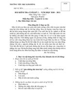
Manufacturing Processes for Engineering Materials, 5th ed.
Kalpakjian •!Schmid
© 2008, Pearson Education
ISBN No. 0-13-227271-7
Weld Joints
FIGURE 12.1 Examples of welded joints.
(a) Butt joint (b) Corner joint (c) T joint (d) Lap joint (e) Edge joint
Method
Strength
Design Variability
Small Parts
Large Parts
Tolerances
Relibility
Ease of Maintenance
Visual Inspection
Cost
Arc welding 1 2 3 1 3 1 2 2 2
Resistance welding 1 2 1 1 3 3 3 3 1
Brazing 1 1 1 1 3 1 3 2 3
Bolts and nuts 1 2 3 1 2 1 1 1 3
Riveting 1 2 3 1 1 1 3 1 2
Fasteners 2 3 3 1 2 2 2 1 3
Seaming, crimping 2 2 1 3 3 1 3 1 1
Adhesive bonding 3 1 1 2 3 2 3 3 2
Note: 1, very good; 2, good; 3, poor.
TABLE 12.1 Comparison of various joining
methods.
Manufacturing Processes for Engineering Materials, 5th ed.
Kalpakjian •!Schmid
© 2008, Pearson Education
ISBN No. 0-13-227271-7
General Summary
Joining Skill Level Welding Current Distor- Cost of
Process Operation Advantage Required Position Type tion
∗
Equipment
Shielded
metal arc
Manual Portable
and flexible
High All ac, dc 1 to 2 Low
Submerged
arc
Automatic High deposi-
tion
Low to
medium
Flat and
horizontal
ac, dc 1 to 2 Medium
Gas metal
arc
Semiautomatic
or automatic
Works with
most metals
Low to
high
All dc 2 to 3 Medium to
high
Gas tung-
sten arc
Manual or
automatic
Works with
most metals
Low to
high
All ac, dc 2 to 3 Medium
Flux-cored
arc
Semiautomatic
or automatic
High deposi-
tion
Low to
high
All dc 1 to 3 Medium
Oxyfuel Manual Portable
and flexible
High All – 2 to 4 Low
Electron
beam, laser
beam
Semiautomatic
or automatic
Works with
most metals
Medium to
high
All – 3 to 5 High
∗
1, highest; 5, lowest
TABLE 12.2 General characteristics of joining processes.
Manufacturing Processes for Engineering Materials, 5th ed.
Kalpakjian •!Schmid
© 2008, Pearson Education
ISBN No. 0-13-227271-7
Oxyfuel Gas Welding
FIGURE 12.2 Three basic types of oxyacetylene flames used in oxyfuel gas welding and cutting
operations: (a) neutral flame; (b) oxidizing flame; (c) carburizing, or reducing, flame. (d) The principle of
the oxyfuel gas welding operation.
(a) Neutral flame (b) Oxidizing flame (c) Carburizing (reducing) flame
2100°C
(3800°F)
1260°C
(2300°F)
Inner cone
3040 to 3300°C
(5500 to 6000°F)
Outer
envelope
Outer envelope
(small and narrow)
Inner cone
(pointed)
Acetylene
feather
Bright luminous
inner cone
Blue
envelope
(d)
Gas mixture
Welding torch
Flame
Solidified
weld metal
Molten
weld metal
Filler rod
Base metal
Manufacturing Processes for Engineering Materials, 5th ed.
Kalpakjian •!Schmid
© 2008, Pearson Education
ISBN No. 0-13-227271-7
Pressure Gas Welding
FIGURE 12.3 Schematic illustration of the pressure gas welding process; (a) before, and
(b) after. Note the formation of a flash at the joint, which can later be trimmed off.
C
2
H
2
+ O
2
mixture
Torch
Flame heating
of surfaces
Clamp
Upsetting
force
Torch
withdrawn
(a) (b)
Manufacturing Processes for Engineering Materials, 5th ed.
Kalpakjian •!Schmid
© 2008, Pearson Education
ISBN No. 0-13-227271-7
Heat Transfer in Welding
Specific Energy, u
Material J/mm
3
BTU/in
3
Aluminum and its alloys 2.9 41
Cast irons 7.8 112
Copper 6.1 87
Bronze (90Cu-10Sn) 4.2 59
Magnesium 2.9 42
Nickel 9.8 142
Steels 9.1-10.3 128-146
Stainless steels 9.3-9.6 133-137
Titanium 14.3 204
TABLE 12.3 Approximate specific energy
required to melt a unit volume of commonly
welded materials.
Heat input
Welding speed
H
l
= e
V I
v
v = e
V I
uA
Manufacturing Processes for Engineering Materials, 5th ed.
Kalpakjian •!Schmid
© 2008, Pearson Education
ISBN No. 0-13-227271-7
Shielded Metal Arc Welding
FIGURE 12.4 (a) Schematic illustration of the shielded metal arc welding process. About one-half of all
large-scale industrial welding operations use this process. (b) Schematic illustration of the shielded
metal arc welding operation.
Welding machine AC or DC
power source and controls
Electrode
Electrode
holder
Arc
Solidified slag
Coating
Electrode
Shielding
gas
Base metal
Arc
Weld metal
Work
Work
cable
Electrode
cable
FIGURE 12.5 A weld zone showing the build-up
sequence of individual weld beads in deep welds.
7
1
2
8
5
4
6
3
Manufacturing Processes for Engineering Materials, 5th ed.
Kalpakjian •!Schmid
© 2008, Pearson Education
ISBN No. 0-13-227271-7
Submerged Arc Welding
FIGURE 12.6 Schematic illustration of the submerged arc welding process and equipment. Unfused
flux is recovered and reused.
Electrode-wire reel
Electrode cable
Voltage and
current control
Voltage-pickup
leads (optional)
Ground
Wire-feed motor
Unfused-flux
recovery tube
Flux hopper
Contact tube
Workpiece
Weld backing
Manufacturing Processes for Engineering Materials, 5th ed.
Kalpakjian •!Schmid
© 2008, Pearson Education
ISBN No. 0-13-227271-7
Gas Metal Arc Welding
FIGURE 12.7 (a) Gas metal arc welding process,
formerly known as MIG welding (for metal inert
gas). (b) Basic equipment used in gas metal arc
welding operations.
Shielding gas
Nozzle
Travel
Arc
Base metal
Molten weld metal
Solidified weld metal
Wire guide and
contact tube
Shielding gas
Solid wire electrode
Current conductor
Workpiece
Gun
Feed control
Control system
Gas out
Gun control
Gas in
Wire
Shielding-gas source
Wire-feed
drive motor
110 V supply
Voltage control
Contactor control
(a)
(b)
Welding machine
Manufacturing Processes for Engineering Materials, 5th ed.
Kalpakjian •!Schmid
© 2008, Pearson Education
ISBN No. 0-13-227271-7
Flux-Cored Arc Welding
FIGURE 12.8 Schematic illustration of the flux-cored arc welding process. This
operation is similar to gas metal arc welding.
Metal droplets covered with
thin slag coating forming
molten puddle
Powdered metal, vapor-or
gas-forming materials,
deoxidizers and scavengers
Insulated extension tip
Current-carrying guide tube
Arc
Base metal
Arc shield composed of
vaporized and slag-forming
compounds protects metal
transfer through arc
Solidified slag
Molten slag
Solidified weld metal
Molten
weld metal
Manufacturing Processes for Engineering Materials, 5th ed.
Kalpakjian •!Schmid
© 2008, Pearson Education
ISBN No. 0-13-227271-7
Electrogas & Electroslag Welding
FIGURE 12.9 Schematic illustration of the
electrogas welding process.
Welding wire
Drive rolls
Electrode conduit
Gas
Welding gun
Welding wire
Water out
Water in
Water in
Water out
Moveable shoe
Fixed shoe
Primary shielding gas
Supplementary
shielding gas
Gas
Gas box
Water
Gas
Oscillator
FIGURE 12.10 Equipment used for electroslag
welding operations.
Control panel
Wire reel
Wire-feed drive
Oscillation (optional)
Molten slag
Molten weld pool
Retaining shoe
Water in
Consumable
guide tube
Water out
Work
Workpiece
(ground) lead
Electrode lead
Power source
Manufacturing Processes for Engineering Materials, 5th ed.
Kalpakjian •!Schmid
© 2008, Pearson Education
ISBN No. 0-13-227271-7
Gas Tungsten Arc Welding
FIGURE 12.11 (a) Gas tungsten arc welding
process, formerly known as TIG welding (for
tungsten inert gas). (b) Equipment for gas
tungsten arc welding operations.
Electrical conductor
Tungsten electrode
Shielding gas
Arc
Travel
Filler wire
Molten weld metal
Gas passage
Filler rod
Cooling-water
supply
Inert-gas
supply
Foot pedal (optional)
Workpiece
Drain
AC or DC
welder
(a)
(b)
Solidified weld metal
Torch
Manufacturing Processes for Engineering Materials, 5th ed.
Kalpakjian •!Schmid
© 2008, Pearson Education
ISBN No. 0-13-227271-7
Plasma Arc Welding
FIGURE 12.12 Two types of plasma arc welding processes: (a) transferred and (b)
nontransferred. Deep and narrow welds are made by this process at high welding
speeds.
Power
supply
Tungsten
electrode
Plasma gas
Shielding gas
(a) (b)
–
Power
supply
–
+
+
Manufacturing Processes for Engineering Materials, 5th ed.
Kalpakjian •!Schmid
© 2008, Pearson Education
ISBN No. 0-13-227271-7
Weld Bead Comparisons
FIGURE 12.13 Comparison of the size of weld beads in (a)
electron-beam or laser-beam welding with that in (b)
conventional (tungsten arc) welding. Source: American Welding
Society, Welding Handbook, 8th ed., 1991.
(a) (b)
FIGURE 12.14 Gillette Sensor razor cartridge,
with laser-beam welds.
Laser welds
Manufacturing Processes for Engineering Materials, 5th ed.
Kalpakjian •!Schmid
© 2008, Pearson Education
ISBN No. 0-13-227271-7
Fusion Weld Characteristics
FIGURE 12.15 Characteristics of a typical fusion
weld zone in oxyfuel gas welding and arc welding
processes.
Molten weld metal
Melting point of base metal
Temperature at which the
base-metal microstructure
is affected
Original
temperature
of base metal
Temperature
Original
structure
Heat-affected
zone
Fusion zone
(weld metal)
Base metal
FIGURE 12.16 Grain structure in (a) a deep
weld and (b) a shallow weld. Note that the grains
in the solidified weld metal are perpendicular to
their interface with the base metal.
(a) (b)
FIGURE 12.17 (a) Weld bead on a cold-rolled nickel strip
produced by a laser beam. (b) Microhardness profile across the
weld bead. Note the lower hardness of the weld bead as
compared with the base metal. Source: IIT Research Institute.
(a) (b)
145
155
260
330
355
0.1 mm
1 mm
0.43 mm
Hardness (HV)
Heat-affected
zone
Melt zone
Manufacturing Processes for Engineering Materials, 5th ed.
Kalpakjian •!Schmid
© 2008, Pearson Education
ISBN No. 0-13-227271-7
Fusion Defects
FIGURE 12.19 Examples
of various incomplete
fusion in welds.
FIGURE 12.18 Intergranular corrosion of a weld
joint in ferritic stainless-steel welded tube, after
exposure to a caustic solution. The weld line is at
the center of the photograph. Source: Courtesy
of Allegheny Ludlum Corp.
Incomplete fusion in fillet welds.
B is often termed !bridging"
B
Weld
Base
metal
(a) (b) (c)
Weld
Incomplete fusion from oxide
or dross at the center of a joint,
especially in aluminum
Incomplete fusion in a
groove weld
Weld
Manufacturing Processes for Engineering Materials, 5th ed.
Kalpakjian •!Schmid
© 2008, Pearson Education
ISBN No. 0-13-227271-7
Defects in Welded Joints
FIGURE 12.20 Examples of various defects in
fusion welds.
(c)
Good weld
(b)
Lack of
penetration
Undercut
Porosity
Overlap
Underfill Crack
Inclusions
(a)
Incomplete
penetration
Base metal
FIGURE 12.19 Examples of various incomplete
fusion in welds.
Toe crack
Underbead
crack
Toe crack
Base metal
Weld
Longitudinal
crack
Longitudinal
crack
Crater
cracks
Weld
Base
metal
(a) (b)
Transverse
crack
Transverse
crack
Base
metal
Weld
Manufacturing Processes for Engineering Materials, 5th ed.
Kalpakjian •!Schmid
© 2008, Pearson Education
ISBN No. 0-13-227271-7
Weld Crack
FIGURE 12.22 Crack in a weld bead, due to the fact that the two components
were not allowed to contract after the weld was completed. Source: Courtesy of
Packer Engineering.
Manufacturing Processes for Engineering Materials, 5th ed.
Kalpakjian •!Schmid
© 2008, Pearson Education
ISBN No. 0-13-227271-7
Distortion in Welds
FIGURE 12.24 Residual stresses developed in a
straight butt joint. Source: Courtesy of the
American Welding Society.
(a) (c) (d)(b)
Transverse shrinkage
Angular distortion
Weld
Longitudinal
shrinkage
Weld
Neutral axis
Weld
Weld
FIGURE 12.23 Distortion and
warping of parts after welding,
caused by differential thermal
expansion and contraction of
different regions of the welded
assembly. Warping can be reduced
or eliminated by proper weld
design and fixturing prior to
welding.
Weld
Base
metal
(b)(a)
Residual stress
Compressive Tensile
Manufacturing Processes for Engineering Materials, 5th ed.
Kalpakjian •!Schmid
© 2008, Pearson Education
ISBN No. 0-13-227271-7
Distortion of Welded Structures
FIGURE 12.25 Distortion of a welded structure. (a) Before welding; (b) during welding, with
weld bead placed in joint; (c) after welding, showing distortion in the structure. Source: After
J.A. Schey.
Rigid frame Hot zone (expanded)
No shape
change
Melt
(pushed
out)
Contraction
Internal
(residual)
tensile
stress
Distortion
(a) (b) (c)
Manufacturing Processes for Engineering Materials, 5th ed.
Kalpakjian •!Schmid
© 2008, Pearson Education
ISBN No. 0-13-227271-7
Tension-Shear Testing
FIGURE 12.26 (a) Types of specimens for tension-shear testing of welds. (b) Wraparound bend test method.
(c) Three-point bending of welded specimens. (See also Fig. 2.21.)
(a) (b)
Longitudinal
tension-shear
Transverse
tension-shear
(c)
Clamp
Roller
Weld
Side bend
Face bend
Root bend
Manufacturing Processes for Engineering Materials, 5th ed.
Kalpakjian •!Schmid
© 2008, Pearson Education
ISBN No. 0-13-227271-7
Tension-Shear Test of Spot Welds
FIGURE 12.27 (a) Tension-shear test for spot welds; (b) cross-tension test; (c) twist
test; (d) peel test.
Hole left in part
Button diameter
indicates quality
(c)
(b)
(a)
(d)
1.
2.
3.
Raised nugget
Manufacturing Processes for Engineering Materials, 5th ed.
Kalpakjian •!Schmid
© 2008, Pearson Education
ISBN No. 0-13-227271-7
Roll Bonding & Ultrasonic Welding
FIGURE 12.28 Schematic illustration
of the roll-bonding, or cladding,
process.
Rolls
Cladding metal
Base metal
FIGURE 12.29 (a) Components of an ultrasonic welding machine for
lap welds. (b) Ultrasonic seam welding using a roller.
Mass
Anvil
Transducer
DC
polarization
supply
AC
power
supply
Direction of
vibration
(a)
Force
Coupling
system
Tip
Workpiece
(b)
Transducer
Toolholder
Roller
Workpiece
Manufacturing Processes for Engineering Materials, 5th ed.
Kalpakjian •!Schmid
© 2008, Pearson Education
ISBN No. 0-13-227271-7
Friction Welding
FIGURE 12.31 Shapes of the fusion zone in
friction welding as a function of the force applied
and the rotational speed.
Force
increased
Beginning of flash
Flash
1.
2.
3.
4.
Force
Speed
Speed, Force, Upset length
Time
Force
Total upset length
Upset length
FIGURE 12.30 Sequence of operations in the
friction welding process. (1) The part on the left
is rotated at high speed. (2) The part on the right
is brought into contact under an axial force. (3)
The axial force is increased, and the part on the
left stops rotating; flash begins to form. (4) After
a specified upset length or distance is achieved,
the weld is completed. The upset length is the
distance the two pieces move inward during
welding after their initial contact; thus, the total
length after welding is less than the sum of the
lengths of the two pieces. If necessary, the flash
can be removed by secondary operations, such
as machining or grinding.
(a) High pressure
or low speed
(b) Low pressure
or high speed
(c) Optimum
Manufacturing Processes for Engineering Materials, 5th ed.
Kalpakjian •!Schmid
© 2008, Pearson Education
ISBN No. 0-13-227271-7
Friction Stir Welding
FIGURE 12.32 The principle of the friction stir welding process. Aluminum-alloy plates
up to 75 mm (3 in.) thick have been welded by this process. Source: TWI, Cambridge,
United Kingdom.
Shouldered
non-consumable
tool
Weld
Probe
Manufacturing Processes for Engineering Materials, 5th ed.
Kalpakjian •!Schmid
© 2008, Pearson Education
ISBN No. 0-13-227271-7
Resistance Spot Welding
FIGURE 12.33 (a) Sequence in the resistance
spot welding operation. (b) Cross-section of a
spot weld, showing weld nugget and light
indentation by the electrode on sheet surfaces.
(b)
Electrode
Sheet
separation
Indentation
Heat-affected zone
Electrode tip
Weld nugget
Electrode
(a)
1. Pressure
applied
2. Current
on
3. Current off,
pressure on
4. Pressure released
Lap joint
Weld nugget
Electrodes
FIGURE 12.34 Two types of electrode designs
for easy access in spot welding operations for
complex shapes.
(a) (b)
Workpiece
Electrodes
Workpiece