Tài liệu Analog Integrated Circuit Design P2 docx
Bạn đang xem bản rút gọn của tài liệu. Xem và tải ngay bản đầy đủ của tài liệu tại đây (895.86 KB, 20 trang )
24
Chapter
1
Integrated-Circuit Devices
and
Modelling
Triode
,,:
region
"DS
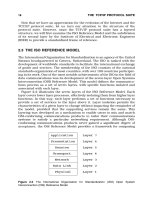
Fig.
1.14
The
ID
versus
VDS
curve
for
an
ideal
MOS
tronsistor. For
VDs
>
VDs-,,,
,
ID
is
approximately constant.
Before
proceeding,
it
is worth discussing the terms
weak,
moderate,
and
strong
inversion.
As just discussed,
a
gate-source voltage greater than
V,,
results in an
inverted channel, and drain-source current can flow. However, as the gate-source
voltage
is
increased, the channel does not become inverted
(i
.e., n-region) suddenly,
but
rather gradually. Thus, it is useful to define three regions of channel inversion
with respect to the gate-source voltage.
In
most circuit applications, noncutoff
MOS-
FET
transistors are operated in strong inversion, with
Veff
>
100
mV
(many
prudent
circuit designers use a
minimum
value
of
200
mV).
As
the
name suggests, strong
inversion occurs when
the
channel is strongly inverted. It should
be
noted that
all
the
equation models in this section assume strong inversion operation. Weak inversion
occurs when
VGS
is approximately
100
mV
or more below
V,,
and is discussed
as
subthreshold operation
in
Section 1.3. Finally, moderate inversion is the region
between weak and strong inversion.
Large-Signal
Modelling
The
triode
region
equation
for
a
MOS transistor relates
the
drain current to the gate-
source
and
drain-source voltages. It
can
be
shown (see Appendix) that this relation-
ship
is given
by
As
V,,
increases,
ID
increases until the drain end of the channel becomes pinched off.
and then
b
no longer increases.
This
pinch-off occurs for
VDG
=
-V,,
,
or approxi-
mately,
VDS
=
VGS
-
Vtn
=
Ve,,
(1.66)
Right at the edge of pinch-off, the drain current resulting from
(1.65)
and the drain
current
in
the active region (which, to
a
first-order approximation, is constant with
1
.2
MOS
Transistors
25
respect to
V,,
)
must have the same value. Therefore, the
active
region equation
can
be found
by
substituting (1.66) into
(1.65),
resulting in
For
V,,
>
Veff,
the current stays constant at the value given
by
(1.67),
ignoring
second-order effects such as the finite output impedance of the transistor. This equation
is perhaps the most important one that describes
the
large-signal operation of a
MOS
transistor.
It
should be noted here that
(1.67)
represents
a
squared current-voltage
relationship for a
MOS
transistor
in
the active region.
In
the case of a
BJT
transistor, an
exponential current-voltage reiationship exists in
the
active region.
As just mentioned.
(
1.67)
implies that the drain current,
ID,
is independent of the
drain-source voltage.
This
independence
is
only true to a first-order approximation.
The major source of error
is
due
to
the channel length shrinking as
V,,
increases. To
see this effect, consider Fig. 1.15, which shows
a
cross section of a transistor in the
active region.
A
pinched-off region with very little charge exists between the drain and
the channel.
The
voltage at the end of the channel closest to
the
drain
is
fixed
at
VGS
-
Vtn
=
Veff.
The voltage difference between the drain and the near end of the
channel lies across a
short
depletion region often called
the
pinch-ofS
region.
As
V,,
becomes
larger
than
V,,,,
this depletion region surrounding the drain junction
increases its width
in
a
square-root relationship with respect to
VDs
This
increase in
the width of the depletion region surrounding the drain junction decreases the effective
channel length. In turn, this decrease in effective channel length increases the drain
current, resulting
in
what
is
commonly referred to-as
channel-lengrh modularion.
To derive
an
equation to account for channel-length modulation, we first make
use of
(I.
I
1)
and denote the width of the depletion region by
xd,
resulting
in
where
I
\
Depletion region
AL
-
&DS
-
v.ff
+
a.
Pinch-off
region
Fig.
1.15
Channel
length
shortening
For
VDs
>
V,,,
26
Chapter
1
IntegratedCircuit
Devices
and
Modelling
and
has units of
m/&.
Note that
NA
is used here since the n-type drain region
is
more heavily doped than the
p-type
channel (i.e.,
ND
>>
N,).
By
writing a Taylor
approximation for
b
around its operating value of
VDs
=
VGs
-
V,,
=
Veff,
we
find
ID
to be given
by
where
ID-,,t
is the drain current when
VDs
=
V,,f
,
or equivalently,
the
drain current
when
the channel-length modulation
is
ignored. Note that in deriving the
final
equa-
tion
of
(1.70).
we
have
used
the
relationshp
dL/aV,,
=
-dx,/dV,,.
Usually,
(1.70)
is
written
as
where
h
is
the output impedance constant (in units of
V-')
given by
Equation
(1.71)
is
accurate until
VDs
is
large enough to cause second-order effects,
often called
short-channel
effects.
For example,
(
1.71) assumes that current flow
down the channel
is
not
veloci9-saturated
(i.e., in~reasing the electric field no longer
increases the
camer speed). Velocity saturation commonly occurs in
new
technolo-
gies
that have very short channel lengths
and
therefore large electric fields. If
VDs
becomes large enough
so
short-channel effects occur,
ID
increases more than is pre-
dicted
by
(1.71).
Of
course, for quite large
values
of
VDs,
the transistor
will
eventu-
ally break down.
A
plot of
ID
versus
VDs
for different values
of
VGS
is
shown
in
Fig. 1.16. Note
that in the active region, the small (but nonzero)
slope
indicates the small dependence
of
ID
on
V,,
.
Triode
,
I
Short-channel
:
effects
I
I
A
Increasing
v,,
,
L
'
1
VGS
>
Vtn
Fig.
1.16
ID
versus
V,,
for
different values
of
V,,.
1.2
MOS
Transistors
27
EXAMPLE
1.8
Find
1,
for
an n-channel transistor that has doping concentrations of
ND
=
NA
=
10",
pnC,,
=
92
p~/~2.
W/L
=
20
pm/2
pm,
VGs
=
1.2
V,
V,,
=
0.8
V,
and
Vos
=
Veff.
Assuming
h
remains constant, estimate the new
value of
1,
if
V,,
is increased
by
0.5
V.
Solution
From (1.69),
we
have
which is used in (1.72) to
find
h
as
h
=
362
x
lop9
=
95.3
x
lo-'
V-I
2x2~ 10-~x&9
Using (1.71), we
find
for
VD,
=
Veff
=
0.4
V,
In
the case where
VDs
=
V,,,
+
0.5
V
=
0.9
V
,
we have
ID,
=
73.6
PA
x
(1
+
h
x
0.3)
=
77.1
pA
Note that this example shows almost a
5
percent increase in drain current for a
0.5
V increase in drain-source voltage.
Body
Effect
The large-signal equations in the preceding section were based on the assumption
that the source voltage was the same as the substrate
(i.e.,
bulk) voltage. However,
often the source
and
substrate can be at different voltage potentials.
In
these situa-
tions,
a second-order effect exists-that
is
modelled as an increase in the threshold
voltage,
V,,
,
as
the source-to-substrate reverse-bias voltage increases. This effect,
typically called the
body
eflect,
is more important for transistors
in
a well of a
CMOS
process where the substrate doping is higher. It should be noted that the body effect
is often important in analog circuit designs and should not be ignored without consid-
eration.
To
account for the body effect, it can
be
shown (see Appendix at the end of this
chapter) that the threshold voltage of an n-channel transistor is now given by
where
V,,,
is the threshold voltage with zero
Vss
(i.e., source-to-substrate voltage),
28
Chapter
1
Integrated-Circuit
Devices
and
Modelling
and
The factor
y
is often called the
body-ef/ect constant
and has units of
fi.
Notice that
y
is proportional to
FA
,lo
so the body effect is larger for transistors
in
a well where
typically the
doping
is
higher than the substrate of the microcircuit.
p-Channel
Transistors
All
of
the preceding equations have been presented for n-channel enhancement tran-
sistors.
In
the case
of
p-channel transistors, these equations can also be used
if
a
negative sign is placed in front of
eveq voltage variable.
Thus,
VGS
becomes
VSG,
VDs
becomes
VSD, Vtn
becomes
-V,,
,
and so on.
The
condition required
for
con-
duction is now
VSG
>
V,,,
where
V,,
is now
a
negative quantity for
an
enhancement
p-channel transistor." The requirement on the source-drain voltage for a p-channel
transistor to be
in
the active region is
VsD
>
VSG
+
Vlp.
The equations
for
I,,
in
both
regions, remain unchanged, because all voltage variables are squared, resulting in
positive hole current flow from the source to the drain in p-channel transistors. For
n-channel depletion transistors, the only difference
is
that
Vtd
<
0
V.
A
typical value
might be
V,,
=
-2
V
.
Small-Signal
Modelling
in
the
Active
Region
The
most commonly used small-signal model for
a
MOS
transistor operating
in
the
active region
is
shown
in
Fig.
1.17.
We
first consider the dc parameters in which all
the capacitors are ignored
(i.e., replaced by open circuits). This leads to the low-
frequency, small-signal model shown in
Fig.
1-18.
The voltage-controlled current
source,
g,~,,,
is
the most important component of the model, with the transistor
transconduc tance
g,
defined as
In
the
active region, we use
(1.67),
which
is
repeated here for convenience,
10.
For
an
n-channel transistor. For
a
p-channel transistor,
y
is proportional to
ND.
1
1.
It
is
possible to realize depletion p-channel transistors.
but
these
are
of little value
and
seldom
worth the
extra
processing involved. Depletion n-channel transislors are also seldom encountered
in
CMOS
microcir-
cuits,
although
they
might
be
wonh
the
extra processing involved in
some
applications. especially
if
they
were
in
a
well.
Fig.
1
.I7
The
small-signal
model
for
a
MOS
transistor
in
the
active
region.
Fig.
1.18
The low-frequency, small-signal model for
an
active
MOS
transistor.
-
and
we apply the derivative shown in
(1.75)
to obtain
or
equivalently,
where the effective gate-source voltage,
V,,,,
is
defined
as
Veff
VGS
-
Vtn.
Thus,
we
see
that the transconductance of a
MOS
transistor
is
directly proportional
to
Veff
.
Sometimes it is desirable to express
g,
in terms
of
ID
rather than
VGS.
From
(
1-76),
we
have
v,,
=
vtn
+
/-
~ncox(w/L)
The
second term in
(1.79)
is
the effective gate-source voltage,
Veff
,
where
30
Chapter
1
IntegrotedCircuit
Devices
and
Modelling
Substituting
(1.80)
in (1.78) results in an alternate expression for
9,.
Thus,
the transistor transconductance
is
proportional to
JD
for
a
MOS
transistor,
whereas
it
is
proportional to
Ic
for
a
BJT.
A
third expression for
g,
is found
by
rearranging
(1.8
1)
and then using
(1.80)
to
obtain
Note that this expression is independent of
pnC,,
and
W/L
,
and it relates the
transconductance to the ratio of drain current
to
effective gate-source voltage. This
simple relationship can be quite useful during an initial circuit design.
The
second voltage-controlled current-source
in
Fig. 1.18, shown as
g,~,,
models the body effect on the small-signal drain current,
id.
When
the source is
connected to small-signal ground, or
when
its voltage does not change appreciably,
then this current source can be ignored. When the body effect cannot be ignored,
we
have
a~,
-
a~,
av,,
gs
=
-
-
avss
av,,av,,
From (1.76) we have
-
Using (1.73), which gives
V,,
as
we have
The negative sign of (1.84) is eliminated by subtracting the current
g,v,
from
the
major component
of
the drain current,
g,~,,
,
as
shown in Fig. 1.18. Thus, using
(1.84) and
(1.86), we have
Note that although
g,
is nonzero
for
V,,
=
0,
if the source
is
connected
to
the bulk,
AVsB
is zero, and so the effect of
gs
does not need to be taken into account. How-
ever, if the source happens to be
biased
at the same potential as the bulk but is not
1.2
MOS
Transistors
31
directly connected to it, then the effect of
g,
should be taken into account since
AVsB
is not necessarily zero.
The
resistor,
rds,
shown
in
Fig.
1.18,
accounts for the finite output impedance
(i.e., it models the channel-length modulation and its effect on the drain current due to
changes in
V,d.
Using
(1.7
l),
repeated here
for
convenience,
we have
where the approximation assumes
h
is
small,
such that
we
can approximate the
drain
bias
current as being
the
same as
ID-sat.
Thus,
where
and
k,,
=
1'
It should
be
noted here that
(1.90)
is
often empirically adjusted to take into account
second-order effects.
EXAMPLE
1.9
Derive
the
low-frequency
model
parameters for an n-channel transistor that has
doping
concentrations of
N,
=
lo2',
N
A
=
pnC,,
=
92
p~/~2,
W/L
=
20
pm/2
pm,
VGs
=
1.2-V,
V,,
=
0.8
V,
and
VDS
=
Veff.
Assume
y
=
0.5
fi
and
VSg
=
0.5
V.
What is the new value of
rdr
if the drain-source volt-
age is increased
by
0.5
V?
Sdufion
Since these parameters
are
the
same
as
in
Example
1.8,
we have
and
from
(1.87),
we have
32
Chapter
1
Integrated-Circuit Devices
and
Modelling
Note that this source-bulk transconductance value
is
about
116
that of the gate-
source transconductance.
For
rds,
we use
(I
-90)
to find
At
this point, it
is
interesting to calculate
the
gain
g,rds
=
52.6,
which
is
the
largest voltage
gain
this single transistor can achieve
for
these
operating
bias
conditions. As we will see, this gain of
52.6
is
much smaller than the corre-
sponding single-transistor gain in
a
bipolar transistor.
Recalling that
V,,,
=
0.4
V,
if
VDs
is increased to
0.9
V1
the
new
value
for
h
is
resulting in a new value of
r,,
given by
An
alternate low-frequency model, known as
a
T
model, is shown in
Fig.
1.19.
This
T
model
can
often result in simpler equations
and
is most often used
by
experi-
enced designers for
a
quick analysis.
At
first glance,
it
might appear that this model
allows for nonzero
gate
current. but
a
quick check confirms that the drain current must
always equal
the
source current, and, therefore, the gate current must always be
zero.
For
this reason, when using the
T
model, one assumes from the beginning that
the
gate
current
is
zero.
Fig.
1
.I9
The small-signal, low-frequency
T
model
for
an
active
MOS
transistor (the body effect
is
not
mod-
elled).
1.2
MOS
Transistors
33
EXAMPLE
1.10
Find
the
T
model parameter,
r,.
for
the
transistor in Example
1.9.
Solution
The value of
r,
is simply the
invcl-se
of
g,!
resulring'in
The value of
rd,
remains
the
same, either
143
WZ
or
170
kR,
depending
on
the
drain-source
voltage.
Most of the capacitors in
the
s~nall-signal
rncx!el
are related to
the
physical
tran-
sistor. Shown
in
Fig.
1.20
is
a cross section of
a
MOS
rr,ansistor, where the parasilic
capacitances are shown at
the
appropriate locations. The
laryest
capacitor in
Fig.
1.20
is
Cg,
.
This
capacitance
is
primarily
due
ro
the change
in
channel charge as a result of
a
chnnse
in
VGS.
It
can be shown
[Tsividis,
19871
that
Cg,
is
approx.irnately
given
by
2
C,,
E
;WLC,,
(1.93)
-
When accuracy
is
important, an additional term should
be
added
to
(1.93)
to
take
into
account
the
overlap between
the
p~tc
and
solrl.ce
junction,
which
sllould include
the,fiinging
ctlpacitance
(fringing capacitance
is
due to boundary effects). This addi-
tional componenl
is
given
by
vs,
=
0
V~~
'
"tn
Polysilicon
p-
substrate
T
Fig.
1.20
A
cross
section of
an
nchonnel
MOS
transistor
showing
!he
small-signal copocitances.
34
Chapter
1
Integrated-Circuit Devices
and
Modelling
where
Lo,
is
the
overlap distance and
is
usually empirically derived. Thus,
when higher accuracy is needed.
The
next largest capacitor
in
Fig.
1.20
is
CJsb,
the capacitor between the source
and the substrate. This capacitor is due to the depletion capacitance of the
reverse-
biased source junction, and it includes the channel-to-bulk capacitance (assuming the
transistor
is
on). Its size is given by
where
A,
is the area of the source junction,
Ach
is the area of the channel (i.e.,
WL)
and
Cj,
is the depletion capacitance
of
the source junction, given
by
fi
Note that the total area of the effective source includes the original area
of
the junc-
tion (when no channel
is
present)
plus
the effective area of the channel.
The
depletion capacitance of the drain
is
smaller because it does not include the
channel area. Here, we have
where
fi
and
Ad
is the area of the drain junction.
The
capacitance
Cgd,
sometimes
cal
led
the
Miller-capacitor,
is
important when the
transistor
is
being used
in
circuits with large voltage gain.
Cgd
is primarily
due
to the
overlap between the gate and the drain and fringing capacitance. Its value is given
by
where,
once again,
Lo,
is usually empirically derived.
Two other capacitors are often important in integrated circuits. These are the
source and drain
sidewall
capacitances,
C,,,
and
Cd-sw.
These capacitances can
be
large because of some highly doped
pi
regions under the thick field oxide calledfield
implants.
The major reason these regions exist
is
to
ensure
there
is
no leakage current
between transistors. Because they are highly doped and they
lie
beside the highly
doped source and drain junctions, the sidewall capacitances can result
in
large
addi-
tional capacitances that must be taken into account
in
determining
Csb
and
Cdb.
The
sidewall capacitances are especially important in modem technologies as dimensions
1.2
MOS
Transistors
35
shrink. For the source, the sidewall capacitance is given by
c,,,
= psc,-,
(1.101)
where
P,
is the length of the perimeter of the source junction, excluding
the
side
adjacent to the channel, and
r\
It should be noted that C,,,, the sidewall capacitance per unit length at 0-V
bias
volt-
age,
can
be
quite
large
because the
field
implants
are
heavily
doped.
The situation
is
similar
for
the
drain
sidewall capacitance, Cd-,,
Cd-sw
=
PdCi-sw
where
Pd
is
the drain perimeter excluding the portion adjacent to the gate.
Finally, the source-bulk capacitance,
C,,
,
is
given by
Csb
=
C'sb
+
Cs-sw
with the drain-bulk capacitance,
Cdb
,
given
by
Cdb
=
C'db
+
Cd-sw
-
EXAMPLE
1.1 1
An
n-channel transistor is modelled as having the following capacitance parameters:
2
Cj
=
2.4
x
pF/(prn)
,
Ci-,,
=
2.0
x
1
o4
pF/pm,
Cox
=
1.9
x
10-~~~1(~rn)~,
4
CgS-,
=
C,,,,
=
2.0
x
10
pF/pm. Find the capacitances
Cg,, Cgd,
Cdb,
and
Csb
for
a
transistor having
W
=
100
m
and
L
=
2
pm
.
Assume the source
and
drain
junctions extend
4
prn
beyond the gate, so that the source and
drain
areas are
A,
=
2
Ad
=
400
(pm) and the perimeter of each
is
P,
=
Pd
=
108
pm.
'
Solution
We
calculate the various capacitances as follows:
Csb
=
C,(As
+
WL)
+
(Ci-,,
x
P,)
=
0.17
pF
Note that the source-bulk and drain-bulk capacitances
are
significant compared
to the gate-source capacitance. Thus, for high-speed circuits, it is important to
keep the
areas
and perimeters of drain and source junctions as
small
as possible
(possibly
by
sharing junctions between transistors, as seen
in
the next chapter).
Small-Signal
Mdling
in
the
Triode
and
Cutoff
Regions
The low-frequency, small-signal model of
a
MOS
transistor in
the
triode region
(which
is
sometimes referred to
as
the linear region) is a resistor.
Using
(1.65), the large-signal
equation
for
ID
in
the
triode region,
results
in
where
rds
is
the
small-signal drain-source resistance
(and
g
ds
is
the
conductance).
For the common
case
of
VDS
near zero, we
have
which is similar to
the
ID-versus-VDs relationship given earlier
in
(1
-60).
EXAMPLE
1.12
For the transistor of Example
1.9,
find the triode model parameters when
V
,s
is
near
zero.
Solution
From
(1.108),
we
have
Note
that
this
conductance value is the same
as
the transconductance of the tran-
sistor,
g,
,
in
the
active region. The resistance,
rds
,
is
simply
l/gds,
resulting
in
rds
=
2.72
kQ.
The
accurate modelling of the high-frequency operation of'a transistor
in
the
triode region
is
nontrivial (even with the use
of
a
computer simulation).
A
moder-
ately accurate model is shown
in
Fig.
1.21, where the gate-to-channel capacitance
1.2
MOS
Transistors
37
v,
Gate-to-channel
capacitance
C
hannel-to-su
bstrate
capacitance
Fig.
1.21
A
distributed
RC
model for a transistor
in
the active
region.
and the channel- to-subs trate capacitance are modelled as distributed elements. How-
ever, the
I-V
relationships of the distributed
RC
elements are highly nonlinear
because the junction capacitances of the source and drain are nonlinear depletion
capacitances,
as
is
the channel-to-substrate capacitance. Also,
if
V,,
is not small,
then the channel resistance per
unit
length should increase as one moves closer to
the drain.
This model is much too complicated for use in hand analysis.
A
simplified model often used for small
VDs
is shown in Fig.
1.22,
where the
resistance,
rds,
is
given
by
(1.108). Here, the gate-to-channel capacitance has been
evenly divided between the source and drain nodes,
Note that this equation ignores the gate-to-junction overlap capacitances, as given
by
(1.94),
which should be taken into account when accuracy is very important.
The
channel-to-substrate capacitance
has
also
been
divided in half and shared between the
source and drain junctions. Each of these capacitors should be added to the
junction-
to-substrate capacitance
and
the junction-sidewall capacitance at the appropriate
Fig.
1.22
A
simplified
triode-region
model
valid for
small
VDs.
38
Chapter
1
IntegratedCircuit
Devices
and
Modelling
node. Thus, we
have
and
Also,
and
It
might
be
noted
that
CSb is often comparable in size to
Cg,
due
to
its
larger area and
the sidewall capacitance.
When the transistor
turns
off,
the model changes considerably.
A
reasonable
model is shown
in
Fig.
1.23.
Perhaps the
biggest
difference is that
rds
is
now infinite.
Another
major
difference is
that
Cg,
and
Cgd
are now much smaller. Since
the
chan-
nel
has disappeared, these capacitors are now
due
to
only overlap and
fringing
capac-
itance.
Thus, we
have
However,
the
reduction of
C,,
and
Cpd
does not mean that
the
total
gate
capaci-
tance
is
necessarily smaller. We now
have
a 'hew" capacitor, Cgb, which
is
the gate-
Fig.
1.23
A
smoll-signal
model
for
a
MOS
FET
that
is
turned
off.
to-substrate capacitance. This capacitor is highly nonlinear and dependent on the gate
voltage.
If
the gate voltage has been very negative for some time and the gate is
accumulated, then we have
C,,
=
AchCO,
=
WLC,,
(1.1
15)
If
the gate-to-source voltage is around
0
V,
then
Cgb
is equal to
C,
in series with the
channel-to-bulk depletion capacitance and is considerably smaller, especially when
the substrate is lightly doped. Another case where
Cgb
is small is just after
a
transistor
has been turned off, before the channel has had time
to
accumulate. Because of the
complicated nature of correctly modelling
C
when
the transistor is turned off,
gb
equation
(
1.1
1
5)
is usually used for hand analysls as a worst-case estimate.
The
capacitors
CSb
and
Cdb
are
also
smaller
when
the
channel
is
not
present. We
now have
CS,-O
=
AsCjo
(1.1
16)
and
Cdb-0
=
Adcia
1.3
ADVANCED
MOS
MODEWNG
In this section,
we
look at three advanced modelling concepts that a microcircuit designer
is
likely to encounter-short-channel effects, subthreshold operation, and leakage cur-
rents.
Short-Channel
Effects
A
number of short-channel effects degrade the operation of
MOS
transistors as device
dimensions
are
scaled down. These effects include mobility degradation, reduced out-
put impedance, and hot-carrier effects (such as oxide trapping and substrate currents).
These short-channel effects will be briefly described here. For more detailed model-
ling of short-channel effects, see [Wolf,
19951.
Transistors that have short channel lengths
and
large electric fields experience a
degradation
in
the effective mobility of their carriers due to several factors. One of
these factors is
the
large lateral electric field (which
has
a
vector in
a
direction perpen-
dicular from the gate into the silicon) caused by large gate voltages and short channel
lengths. This large lateral field causes the effective channel depth
to
change and also
causes more electron collisions, thereby lowering the effective mobility. Another fac-
tor causing this degradation is that, due to large electric fields,
carrier velocity begins
to saturate.
A
first-order approximation that models this carrier-velocity saturation for
electrons
is
given
by
where
E
is the electric field and
E,
is the critical electrical field, which might be on
the
order of
1.5
x
lo6
V/m. Using this equation in the derivation of the
ID-V,,,
40
Chopter
1
Integrated-Circuit Devices and
Modelling
chnracteriqtics of
a
MOS
rrrinsistor.
it
can be shown [Gr:~y, 19931 that
the
drain cur-
re.nt is now given
by
where
e
=
I
/(LIE,)
and. for
a
0.8-pm
tcchnalogy. might have
a
typical value
of
0.6
V-I.
11 can be shown that ths mobility degradation is ecjui\~nlent
tc~
a
finitc scnes
source ~.csistance given
by
For
p,C,,
=
90
p.A/'V2.
this
resistance
might
be
on
the
order
of
6
k!J
per
prn
of
width (again, for
a
O'.R-pm-long transistor). This equivalent series solrrce resist:lnce
is
typically larger than the physical vource resil;t;~nce. 'I'his saturnlion c~tuscs the square-
law chan~ctcristic of the current-voltage relntionship to
be
inaccurate, and the true
relationsliip will be somewhere between lincar and square. In
many
voltage-to-current
conversion circuits that rely on
the
square-law characteristic, this inaccuracy can
be
a
major source of error. Taking channel lengths larger than the rninin~um allowed helps
to nlinimizc this degradation.
Transistors wit11 short channel lengths also experience
a
reciuccd output impcd-
ance
because
depletion
region variations at the drain end (~vh-icb affect
the
effective
cha.nnel length) have an increased proponiond effect on the drain current.
In
addition,
a
phenomenon
known
as
drain-induced barrier lowering
(DIBL)
effectjveIy lowers
V,
as
V,,
is
increnscd, thereby forther lowering the output impedance of
a
short-
channel device. This lower oiltput impedance is the main reason
that
cascode current
mirrors
are
beconling increasingly popular.
Another important short-channel
cffcct
is
due
to
hor
cat-t.ir.r.v.
These
high-velocity
carriers can cause harmful effects, such as the generation of electron-hole pairs
by
impact ionization and avalanching. These extra eleclson-hole pairs can cause currents
to flow from the drain to the subsrrnte, as sl~own
in
Fig.
1.24.
This effect can be mod-
0
0
-
Gate
-
current
n"
Punch-through
current
p
Drain-to-substrate
Q
ccurrent
-
-
-
Fig.
1.24
Drain-to-substrate
current caused
by
electron-hole poirs generoted
by
impact
ionization ot drain end of channel.
1.3
Advanced MOS Modelling
41
elled
by
a finite drain-to-ground impedance. As a result, this effect
is
one of the major
limitations on achieving very high output impedances of
cascode current sources.
In
addition, this current flow can cause voltage drops across the substrate and possibly
cause latch-up, as the next section describes.
Another hot-carrier effect occurs when electrons gain energies high enough so
they can tunnel into and possibly through the thin gate oxide. Thus, this effect can
cause dc gate currents. However, often more
harmful is the fact that any charge
trapped in the oxide will cause a shift in transistor threshold voltage.
As
a
result, hot
carriers are one of the major factors limiting the
long-term reliability of
MOS
transis-
tors.
A
third hot-carrier effect occurs when electrons with enough energy
punch
through
from the source to the drain. As
a
result, these high-energy electrons are no
longer limited by the drift equations governing normal conduction along the channel.
This
mechanism is somewhat similar to punch-through in a bipolar transistor, where
the collector depletion region extends right through the base region to the emitter.
In
a
MOS
transistor, the channel length becomes effectively zero, resulting in unlimited
current flow (except for the series source and drain impedances, as well as external
circuitry). This effect is
an
additional cause
of
lower output impedance and possibly
transistor breakdown.
It
should be noted that all of the hot-carrier effects just described are more pro-
nounced for
n-channel transistors than for their p-channel counterparts because elec-
trons have larger velocities than holes.
Finally, it should be noted that short-channel transistors have much larger sub-
threshold currents than long-channel devices.
-
Subthreshold
Operation
The device equations presented for
MOS
transistors in the preceding sections are
all
based on the assumption that
Vef,
(i.e.,
VGS
-
Vt
)
is greater than about
100
mV
and
the device is in strong inversion. When this is not the case, the accuracy of the square-
law equations is poor.
If
V,,,
<
-
100
m
V,
the transistor is in weak inversion and is
said to be operating in the
subthreshold
region.
In this region, the transistor
is
more
accurately
modelled
by
an exponential relationship between its control voltage and
current, somewhat similar to
a
bipolar transistor. In the subthreshold region, the drain
current is approximately given
by
the exponential relationship [Geiger,
19901
where
and it has been assumed that
Vs
=
0
and
VDs
>
75
mV
.
The constant
ID,
might be
around
20
nA.
42
Chapter
1
IntegratedCircuit Devices
and
Modelling
Although the transistors have
an
exponential relationship in this region, the trans-
conductances are still small because of the small bias currents, and the transistors are
slow because of small currents for charging and discharging capacitors. In addition,
matching between transistors suffers because
it
now strongly depends on transistor-
threshold-voltage matching. Normally, transistors are not operated in the subthreshold
region, except in very low-frequency and low-power applications.
Leakage Currents
An
important second-order device limitation in some applications is the leakage
cur-
rent
of
the
junctions.
For
example,
this
leakage
can
be
important
in
estimating
the
maximum time a sample-and-hold circuit or a dynamic memory cell can be left in
hold mode. The leakage current of a reverse-biased junction
(not
close to breakdown)
is approximately given by
where
Aj
is the junction area,
ni
is
the
intrinsic concentration of carriers in undoped
silicon,
T,
is the effective minority carrier lifetime, and
x,.,
is the thickness of the
depletion region.
.to
is
given
by
-t
where
5,
and
T,,
are the electron and hole lifetimes. Also,
xd
is given by
and
ni
is given
by
ni
JN,NV
e(-Eg)'(kT)
where
Nc
and
Nv
are the densities of states in the conduction and valence bands and
Eg
is
the
difference in energy between the two bands.
Since the intrinsic concentration,
ni,
is a strong function of temperature (it
approximately doubles for every temperature increase
of
I
I
"C
for
silicon), the leak-
age current is also a strong function of temperature. Roughly speaking, the leakage
current also doubles for every 11
"C
rise
in temperature. Thus, the leakage current at
higher temperatures is much larger than at room temperature. This leakage current
imposes a maximum time on
how
long a dynamically charged signal can be main-
tained in a
high
impedance state.
1
4
BIPOLAR-JUNCTION TRANSISTORS
In the early electronic years, the majority
of
microcircuits were realized using bipolar-
junction transistors
(BJTs). However, in
the
late 1970s, microcircuits that used MOS
1.4
Bipolar-Junction Tronsistors
43
transistors began to dominate the industry,
with
BJT
mjcrucircuits
remaining
popular
for high-speed applications. More recently, bipolar
CMOS
(I3iCMOS) ~echnologies,
wherc both bipolar and
MOS
transistors
are
realized
in
the s~me
microcircuit^
have
grown
in
populasity.
BiCMOS
~echnologies
are
particularly ntt1,nctivefor mixed analog-
digitill ~~pplications.
and
thus
it
is
irnpo~tant
frlr
an ontrlog tlchig~~cr to become h~uiliar
with
bipolar
Jc\
iccs.
Modern bipolar transistors can have unity-gain I'i.tquencics as
hgh
as
L5
to
45
GHz
or more, compared
to
unity-gain frequcncies of only
I
to
4
GHz
for
MOS
transistors that use
a
technology with qirnilal- lithography resolution. I.in.fortunately, in
bipolar ~r,ansistors,
the
/)use
control terrnini~l
h:~s
a
nonzero input current whcn
the
transistor
is
conducting current (from the coIlcctor
to
the emitter fi)r an
npn
transistor;
from the emitter to the
collector
for
a
pnp
transistor). Fortunately,
at
low frequencies,
the base current is
much
smallcr
than the collector-to-emitter current-it may be only
11100
of the coltector current for an
npn
transistor. For lateral
pnp
transistors, the
base current may be as
larpe
as
1/20
of
thc'
c~nittzr-to-collector current.
A
typical cross aection
of
an
npn
bipolar-junction transisror is shown in Fig.
I
.25.
Although this structure looks quite
complicated.
it
corresponds approximately to the
equivalent structure shown
in
Fig.
1.26.
In
a
good
BJT
transistor. the
width
of the base
Base
The
base contact surrounds
the
emitter contact
to
7
minimize
base resistanc
Substrate
or
bulk
P-
Fig.
1.25
A
cross
section of on
npn
bipolar-junction transistor.
Emitter
co~.ctor
Fig.
1.26
A
simplified
structure of
an
npn transisfor