Tài liệu Project Planning and Control Part 4 pdf
Bạn đang xem bản rút gọn của tài liệu. Xem và tải ngay bản đầy đủ của tài liệu tại đây (389.29 KB, 38 trang )
17
Computer analysis
Most manufacturers of computer hardware, and
many suppliers of computer software, have
written programs for analysing critical path
networks using computers. While the various
commercially available programs differ in detail,
they all follow a basic pattern, and give, by and
large, a similar range of outputs. In certain
circumstances a contractor may be obliged by his
contractual commitments to provide a computer-
ized output report for his client. Indeed, when a
client organization has standardized on a partic-
ular project management system for controlling
the overall project, the contractor may well be
required to use the same proprietary system so
that the contractor’s reports can be integrated into
the overall project control system on a regular
basis.
History
The development of network analysis techniques
more or less coincided with that of the digital
computer. The early network analysis programs
were, therefore, limited by the storage and
processing capacity of the computer as well as
the input and output facilities.
Project Planning and Control
The techniques employed mainly involved producing punched cards (one
card for each activity) and feeding them into the machine via a card reader.
These procedures were time consuming and tedious, and, because the
punching of the cards was carried out by an operator who usually understood
little of the program or its purpose, mistakes occurred which only became
apparent after the printout was produced.
Even then, the error was not immediately apparent – only the effect. It then
often took hours to scan through the reams of printout sheets before the actual
mistake could be located and rectified. To add to the frustration of the planner,
the new printout may still have given ridiculous answers because a second
error was made on another card. In this way it often required several runs
before a satisfactory output could be issued.
In an endeavour to eliminate punching errors attempts were made to use
two separate operators, who punched their own set of input cards. The cards
were then automatically compared and, if not identical, were thrown out,
indicating an error. Needless to say, such a practice cost twice as much in
manpower.
Because these early computers were large and very expensive, usually
requiring their own air-conditioning equipment and a team of operators and
maintenance staff, few commercial companies could afford them. Computer
bureaux were therefore set up by the computer manufacturers or special
processing companies, to whom the input sheets were delivered for punching,
processing and printing.
The cost of processing was usually a lump sum fee plus x pence per activity.
Since the computer could not differentiate between a real activity and a
dummy one, planners tended to go to considerable pains to reduce the number
of dummies to save cost. The result was often a logic sequence, which may
have been cheap in computing cost but was very expensive in application,
since frequently important restraints were overlooked or eliminated. In other
words, the tail wagged the dog – a painful phenomenon in every sense. It was
not surprising, therefore, that many organizations abandoned computerized
network analysis or, even worse, discarded the use of network analysis
altogether as being unworkable or unreliable.
There is no doubt that manual network analysis is a perfectly feasible
alternative to using computers. Indeed, one of the largest petrochemical
complexes in Europe was planned entirely using a series of networks, all of
which were analysed manually.
128
Computer analysis
The PC
The advent of the personal computer (PC) significantly changed the whole
field of computer processing. In place of the punched card or tape we now
have the computer keyboard and video screen, which enable the planner to
input the data direct into the computer without filling in input sheets and
relying on a punch operator. The information is taken straight from the
network and displayed on the video screen as it is ‘typed’ in. In this way, the
data can be checked or modified almost instantaneously.
Provided sufficient information has been entered, trial runs and checks can
be carried out at any stage to test the effects and changes envisaged. Modern
planning programs (or Project Management systems, as they are often called)
enable the data to be inputted in a random manner to suit the operator,
provided, of course, that the relationship between the node numbers (or
activity numbers) and duration remains the same.
There are some programs which enable the network to be produced
graphically on the screen as the information – especially the logic sequence
– is entered. This, it is claimed, eliminates the need to draw the network
manually. Whether this practice is as beneficial as suggested is very
doubtful.
For a start, the number of activities which can be viewed simultaneously
on a standard video screen is very limited, and the scroll facility which
enables larger networks to be accommodated does not enable an overall
view to be obtained at a glance. The greatest drawback of this practice,
however, is the removal from the network planning process of the team
spirit, which is engendered when a number of specialists sit down with the
planner round a conference table to ‘hammer out’ the basic shape of the
network (see Chapter 20). Most problems have more than one solution, and
the discussions and suggestions, both in terms of network logic and
durations, are invaluable when drafting the first programs. These meetings
are, in effect, a brainstorming session at which the ideas of the various
participants are discussed, tested and committed to paper. Once this draft
network has been produced, the planner can very quickly input it into the
computer and call up a few test runs to see whether the overall completion
date can, in fact, be achieved. If the result is unsatisfactory, logic and/or
duration changes can be discussed with the project team before the new data
are processed again by the machine. The speed of the new hardware makes
it possible for the computer to be part of the planning conference, so that
(provided the planner/operator is quick enough) the ‘what if’ scenarios can
be tested while the meeting is in progress. A number of interim test runs
129
Project Planning and Control
can be carried out to establish the optimum network configuration before
proceeding to the next stage. Even more important, errors and omissions can
be corrected and durations of any or all activities can be altered to achieve
a desired interim or final completion date.
The relatively low cost of the modern PCs has enabled organizations to
install planning offices at head office and sites as well as at satellite offices,
associate companies and offices of vital suppliers, contractors and sub-
contractors. All these PCs can be linked to give simultaneous printouts as well
as supplying up-to-date information to the head office where the master
network is being produced. In other words, the IT (Information Technology)
revolution has made an important impact on the whole planning procedure,
irrespective of the type or size of organization.
The advantages of PCs are:
1 The great reduction in the cost of the hardware, making it possible for small
companies, or even individuals, to purchase their own computer system.
2 The proliferation of inexpensive, proven software of differing sophistica-
tion and complexity, enabling relatively untrained planners to operate the
system.
3 The ability to allow the planner to input his or her own program or
information via a keyboard and VDU.
4 The possibility to interrogate and verify the information at any stage on the
video screen.
5 The speed with which information is processed and printed out either in
numerical (tabular) or graphical form.
Programs
During the last few years a large number of proprietary programs have been
produced and marketed. All these programs have the ability to analyse
networks and produce the standard output of early and late start and the three
main types of float, i.e. total, free and independent. Most programs can deal
with either arrow diagrams or precedence diagrams, although the actual
analysis is only carried out via one type of format.
The main differences between the various programs available at the time of
writing are the additional facilities available and the degree of sophistication
of the output. Many of the programs can be linked with ‘add-on’ programs to
give a complete project management system covering not only planning but
also cost control, material control, site organization, procurement, stock
130
Computer analysis
control, etc. It is impossible to describe the many intricacies of all the
available systems within the confines of this chapter, nor is it the intention to
compare one system with another. Such comparison can be made in terms of
cost, user friendliness, computing power, output sophistication or range of
add-ons. Should such surveys be required, it is best to consult some of the
specialist computer magazines or periodicals, who carry out such comparisons
from time to time.
Some of the programs more commonly available to date are listed in Table
17.1, but to give a better insight into the versatility of a modern program one
of the more sophisticated systems is described in some detail in Chapter 30.
The particular system was chosen because of its ability to be linked with the
SMAC system described in Chapter 27 of this book. Although the terms are
different – e.g. ‘Value Hour’ is called ‘Earned Value’ – the result is a useful
coordinated system giving the essential relationship between the planning and
the cost functions.
The chosen system, Hornet Windmill, is capable of producing both AOA
and AON network outputs using a plotter.
Commercial programs
At the time of going to press the network analysis programs shown in Table
17.1 are commercially available, but new ones are constantly being added to
the list. The cost of these systems varies from as little as £99 to over £2000,
and the reader is therefore advized to investigate each ‘offer’ in some depth
to ensure value for money. A simple inexpensive system may be adequate for
a small organization running small projects or wishing to become familiar
with computerized network analysis. Larger companies, whose clients may
demand more sophisticated outputs, may require the more expensive systems.
Indeed, the choice of a particular system may well be dictated by the client,
as described earlier.
The current list is clearly not claimed to be 100% complete.
Outputs
The output (or printout formats) available from modern PCs are becoming
more varied and sophisticated as development and enhancement of programs
131
Project Planning and Control
Table 17.1 Project management software (current)
System Marketing company
Acos Compact D & L Computer Services
Acos Plus 1 D & L Computer Services
Apache Project Aran Ltd
Artemis Project View Artemis
Artemis 7000 Artemis
Artemis 9000 Artemis
Cascade Mantix Systems Ltd
CA Super Project Computer Associates
Client CSSP
Controller (for Oracle) Monitor Management & Controls
Controller (for Artemis) Monitor Management & Controls
CS Project Life Leach Management Systems
CS Project Professional Leach Management Systems
4C for Windows Intersoftware UK
Hornet XK Claremont Controls Ltd
Hornet 5000 Claremont Controls Ltd
Hornet Windmill Claremont Controls Ltd
Interface Toolkit Chaucer Group Ltd
Jobmaster Jobmaster plc
LAMP Bensasson & Chalmers
Micro Planner Expert Micro Planner International
Micro Planner Manager Micro Planner International
Micro Planner V6 Micro Planner International
Micro Planner Professional Micro Planner International
Micro Planner P 1000 Micro Planner International
Micro Planner V4 Micro Planner International
MS Project Microsoft
Open Plan Welcom Software Technology
PACS Herkemij & Partners
Panorama Panorama Software
Pertmaster for Windows People in Technology
Plantrac Computerline
Plantrac Outlook Computerline
Power Project Asta Development Corporation
Primavera Project Planner (3P) Primavera Systems Inc.
Project Gateway Deepak Sareen Associates
Project Scheduler Tekware Ltd
Project Workbench (PMW) ABT International
7000 Plus PMP Services
QEI PCF Ltd
QEI Exec PCF Ltd
Schedule Publisher Advanced Management Solutions
Sure Trak Project Planner Primavera Systems Inc.
Trackstar Complete Project Management
132
Computer analysis
continue. However, the basic outputs produced by the early mainframe
machines are still the core of the output reports available. These are:
Total float (including the critical path for which the total float is
obviously 0)
Preceding event (or preceding activity)
Activity number
Earliest start
Latest start
Earliest finish
Latest finish.
Of the above, the first four are the most useful. The total float shows the order
of criticality, starting with the critical activities. As the float increases, the
criticality reduces.
The preceding event report enables a particular activity to be found rapidly,
since activities are listed in ascending order of preceding event numbers.
When a grid system is used, the order is by ascending number of each
horizontal band. For AON methods, preceding activity numbers are given.
The activity number report is useful when the critical path program is
related to a cost analysis system, such as SMAC. The time and cost position
can therefore be found for any particular activity in which one may be
interested. The earliest start report is used primarily to find all the activities
which should be started (as early as possible) by a required date. The
chronological listing of earliest starts enables this be found very rapidly.
The actual format of the reports is slightly different for every software
company, and in most cases can be produced in bar chart format as well as
being grouped by report code, i.e. a separate report for each discipline,
department, sub-contractor, etc. These report codes can, of course, be edited
to contain only such information as is required (or considered to be necessary)
by the individual departments.
It is recommended that the decision to produce any but the most basic
printouts, as well as any printouts in report code, be delayed until the
usefulness of a report has been studied and discussed with department
managers. There is always a danger with computer outputs that recipients
request more reports than they can digest, merely because they know they
are available at the press of a button. Too much paper becomes self-
defeating, since the very bulk frightens the reader to the extent of it not
being read at all.
133
Project Planning and Control
With the proliferation of the personal computer (PC) and the expansion of
IT, especially the Internet, many of the projects management techniques can
now be carried out on-line. The use of e-mail and the Intranet allows
information to be distributed to the many stakeholders of a project almost
instantaneously. Where time is important – and it nearly always is – such a fast
distribution of data or instructions can be of enormous benefit to the project
manager. It does, however, require all information to be carefully checked
before dissemination precisely because so many people receive it at the same
time. It is an unfortunate fact that computer errors are more serious for just
this reason as well as the naive belief that computers are infallible.
134
18
Simple examples
To illustrate the principles set out in the previous
chapter let us now examine two simple
examples.
Example 1
For the first example let us consider the rather
mundane operation of getting up in the morning,
and let us look at the constituent activities
between the alarm going off and boarding our
train to the office.
Project Planning and Control
The list of activities – not necessarily in their correct sequence – is roughly
as follows:
Time (min)
A switch off alarm clock 0.05
B lie back and collect your thoughts 2.0
C get out of bed 0.05
D go to the bathroom 0.10
E wash or shower 6.0
F brush teeth 3.0
G brush hair 3.0
H shave (if you are a man) 4.0
J boil water for tea 2.0
K pour tea 0.10
L make toast 3.0
M fry eggs 4.0
N serve breakfast 1.0
P eat breakfast 8.0
Q clean shoes 2.0
R kiss wife goodbye 0.10
S don coat 0.05
T walk to station 8.0
U queue and buy ticket 3.0
V board train 1.0
50.45
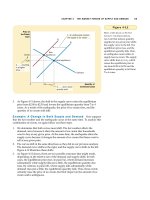
The operations listed above can be represented diagrammatically in a network.
This would look something like that shown in Figure 18.1.
It will be seen that the activities are all joined in one long string, starting
with A (switch off alarm) and ending with V (board train). If we give each
activity a time duration, we can easily calculate the total time taken to perform
the complete operation by simply adding up the individual durations. In the
example given, this total time – or project duration – is 50.45 minutes. In
theory, therefore, if any operation takes a fraction of a minute longer, we will
miss our train. Consequently, each activity becomes critical and the whole
sequence can be seen to be on the critical path.
In practice, however, we will obviously try to make up the time lost on an
activity by speeding up a subsequent one. Thus, if we burn the toast and have
to make a new piece, we can make up the time by running to the station
instead of walking. We know that we can do this because we have a built-in
136
A
H
B
J
R
C
K
S
D
L
T
E
M
U
F
N
V
G
P
.05
4
2
2
2
.1
.05
.1
.05
.1
3
8
6
4
3
3
1
1
3
8
Simple examples
margin or float in the journey to the station. This float is, of course, the
difference between the time taken to walk and run to the station. In other
words, the path is not as critical as it might appear, i.e. we have not in our
original sequence – or network – pared each activity down to its minimum
duration. We had something up our sleeve.
However, let us suppose that we cannot run to the station because we have
a bad knee; how then can we make up lost time? This is where network
analysis comes in. Let us look at the activities succeeding the making of toast
(L) and see how we can make up the lost time of, say, two minutes. The
remaining activities are:
Times (min)
M fry eggs 4.0
N serve breakfast 1.0
P eat breakfast 8.0
Q clean shoes 2.0
R kiss wife goodbye 0.10
S don coat 0.05
T walk to station 8.0
U queue and buy ticket 3.0
V board train 1.0
27.15
The total time taken to perform these activities is 27.15 minutes.
137
Figure 18.1
Project Planning and Control
The first question therefore is, have we any activity which is unnecessary?
Yes. We need not kiss the wife goodbye. But this only saves us 0.1 minute and
the saving is of little benefit. Besides, it could have serious repercussions. The
second question must therefore be, are there any activities which we can
perform simultaneously? Yes. We can clean our shoes while the eggs fry. The
network shown in Figure 18.2 can thus be redrawn as demonstrated in Figure
18.3. The total now from M to V adds up to 25.15 minutes. We have,
therefore, made up our lost two minutes without apparent extra effort. All we
have to do is to move the shoe-cleaning box to a position in the kitchen where
we can keep a sharp eye on the eggs while they fry.
Encouraged by this success, let us now re-examine the whole operation to
see how else we can save a few minutes, since a few moments extra in bed are
well worth saving. Let us therefore see what other activities can be performed
simultaneously:
1 We could brush our teeth under the shower;
2 We could put the kettle on before we shaved so that it boils while we
shave;
3 We could make the toast while the kettle boils or while we fry the eggs;
4 We could forget about the ticket and pay the ticket collector at the other
end;
5 We can clean our shoes while the eggs fry as previously discussed.
Having considered the above list, we eliminate (1) since it is not nice to spit
into the bath tub, and (4) is not possible because we have an officious guard
on our barrier. Se we are left with (2), (3) and (5). Let us see what our network
looks like now (Figure 18.4). The total duration of the operation or
138
Figure 18.2
Figure 18.3
Simple examples
programme is now 43.45 minutes, a saving of seven minutes or over 13% for
no additional effort. All we did was to resequence the activities. If we moved
the wash basin near the shower and adopted the ‘brush your teeth while you
shower’ routine, we could save another three minutes, and if we bought a
season ticket we would cut another three minutes off our time. It can be seen,
therefore, that by a little careful planning we could well spend an extra 13
minutes in bed – all at no extra cost or effort.
If a saving of over 25% can be made on such a simple operation as getting
up, it is easy to see what tremendous savings can be made when planning
complex manufacturing or construction operations.
Let us now look at our latest network again. From A to G the activities are
in the same sequence as on our original network. H and J (shave and boil
water) are in parallel. H takes four minutes and J takes two. We therefore have
two minutes float on activity J in relation to H. To get the total project duration
we must, therefore, use the four minutes of H in our adding-up process, i.e. the
longest duration of the parallel activities.
Similarly, activities L, M and Q are being carried out in parallel and we
must, therefore, use M (fry eggs) with its duration of four minutes in our
calculation. Activity L will, therefore, have one minute float while activity Q
has two minutes float. It can be seen, therefore, that activities H, L and Q
could all be delayed by their respective floats without affecting the overall
programme. In practice, such a float is absorbed by extending the duration to
match the parallel critical duration or left as a contingency for disasters. In our
example it may well be prudent to increase the toast-making operation from
three minutes to four by reducing the flame on the grill in order to minimize
the risk of burning the bread!
139
Figure 18.4
Project Planning and Control
Example 2
Let us now look at another example. Supposing we decide to build a new
room into the loft space of our house. We decide to coordinate the work
ourselves because the actual building work will be carried out by a small
jobbing builder, who has little idea of planning, while the drawings will be
prepared by a freelance architect who is not concerned with the meaning of
time. If the start of the programme is the brief to the architect and the end
is the fitting of carpets, let us draw up a list of activities which we wish
to monitor to ensure a speedy completion of the project. The list would be
as follows:
Days
A brief architect 1
B architect produces plans for planning permission 7
C obtain planning permission 60
D finalize drawings 10
E obtain tenders 30
F adjudicate bids 2
G builder delivers materials 15
H strip roof 2
J construct dormer 2
K lay floor 2
L tile dormer walls 3
M felt dormer roof 1
N fit window 1
P move CW tank 1
Q fit doors 1
R fit shelves and cupboards 4
S fit internal lining and insulation 4
T Lay electric cables 2
U cut hole in existing ceiling 1
V fit stairs 2
W plaster walls 2
X paint 2
Y fit carpets 1
156
Rather than draw out all these activities in a single long string, let us make
a preliminary analysis on which activities can be carried out in parallel. The
following immediately spring to mind.
140
Simple examples
1 Final drawings can be prepared while planning permission is obtained.
2 It may even be possible to obtain tenders during the planning permission
period, which is often extended.
3 The floor can be laid while the dormer is being tiled.
The preliminary network would, therefore, be as shown in Figure 18.5.
If all the activities were carried out in series, the project would take 156
days. As drawn in Figure 18.5, the duration of the project is 114 days. This
shows already a considerable saving by utilizing the planning permission
period for finalizing drawings and obtaining tenders.
However, we wish to reduce the overall time even further, so we call the
builder in before we start work and go through the job with him. The first
question we ask is how many men will he employ. He says between two and
four. We then make the following suggestions:
1 Let the electrician lay the cables while the joiners fit the stairs.
2 Let the plumber move the tank while the roof of the dormer is being
constructed.
3 Let the glazier fit the windows while the joiner fits the shelves.
4 Let the roofer felt the dormer while the walls are being tiled.
5 Fit the doors while the cupboards are being built.
141
Figure 18.5
A
1
N
1
M
1
B
7
Q
1
C
60
S
4
D
10
T
2
R
4
P
1
F
2
U
1
E
30
K
2
G
15
V
2
H
2
W
2
J
2
X
2
L
3
Y
1
Project Planning and Control
The builder may object that this requires too many men, but you tell him that
his overall time will be reduced and he will probably gain in the end. The
revized network is, therefore, shown in Figure 18.6. The total project duration
is now reduced to 108 days. The same network in precedence format (AoN)
is shown in Figure 18.7
If we now wish to reduce the period even further we may have to pay the
builder a little extra. However, let us assume that time is of the essence since
our rich old uncle will be coming to stay and an uncomfortable night on the
sofa in the sitting room might prejudice our chances in his will. It is
financially viable, therefore, to ensure that the room will be complete.
Supposing we have to cut the whole job to take no longer than 96 days.
Somehow we have to save another 12 days. First, let us look at those activities
which have float. N and Q together take two days while R takes four. N and
Q have, therefore, two days float. We can utilize this by splitting the operation
142
Figure 18.6
Figure 18.7 Precedence network
Simple examples
S (fit internal lining) and doing two days’ work while the shelves and
cupboards are being built. The network of this section would, therefore,
appear as in Figure 18.8. We have saved two days provided that labour can be
made available to start insulating the rafters.
If we adjudicate the bids (F) before waiting for planning permission, we can
save another two days. This section of the network will, therefore, appear as
in Figure 18.9.
Total saving to this stage is 2 + 2 = 4 days. We have to find another eight
days, so let us look at the activities which take longest: C (obtaining planning
permission) cannot be reduced since it is outside our control. It is very
difficult to hurry a local authority. G (builder delivers materials) is difficult to
reduce since the builders will require a reasonable mobilization period to buy
materials and allocate resources. However, if we select the builder before
planning permission has been received, and we do, after all, have 18 days float
in loop D-E-F, we may be able to get him to place preliminary orders for the
materials required first, and thus enable work to be started a little earlier. We
may have to guarantee to pay the cost for this material if planning permission
is not granted, but as time is of the essence we are prepared to take the risk.
The saving could well be anything from one to 15 days.
Let us assume we can realistically save five days. We have now reduced the
programme by 2 + 2 + 5 = 9 days. The remaining days can now only be saved
by reducing the actual durations of some of the activities. This means more
143
Figure 18.8
Figure 18.9
Project Planning and Control
resources and hence more money. However, the rich uncle cannot be put off,
so we offer to increase the contract sum if the builder can manage to reduce
V, T, W and X by one day each, thus saving three days altogether. It should
be noted that we only save three days although we have reduced the time of
four activities by one day each. This is, of course, because V and T are carried
out in parallel, but our overall period – for very little extra cost – is now 96
days, a saving of 60 days or 38%.
Example 3
This example from the IT industry, uses the AoN (precedence) method of
network drafting. This is now the standard method for this industry, probably
because of the influence of MS Project and because networks in IT are
relatively small, when compared to the very large networks in construction
which can have between two hundred and several thousand activities. The
principles are of course identical.
A supermarket requires a new stock control system linked to a new check-
out facility. This involves removing the existing check-out, designing and
manufacturing new hardware and writing new software for the existing
computer, which will be retained.
The main activities and durations (all in days) for this project are as
follows:
Days
A Obtain brief from client (the supermarket owner) 1
B Discuss the brief 2
C Conceptual design 7
D Feasibility study 3
E Evaluation 2
F Authorization 1
G System design 12
H Software development 20
J Hardware design 40
K Hardware manufacture 90
L Hardware delivery (transport) 2
M Removal of existing check-out 7
N Installation of new equipment 6
P Testing on site 4
Q Hand over 1
R Trial operation 7
S Close out 1
144
AB
J
N
C
K
P
D
L
Q
E
M
RS
FGH
13
68
166
10
160
170
13
160
171
15
165
178 179
16 28 48
13
68
166
10
158
170
13
160
170
5
166
178 179
16 28 160
12
40
6
7
2
4
3
2
1
2
7
71
11220
00
0
0
0
0
0
0
0
0
0
1
00
0 0 112
01
28
160
3
68
166
10
158
170
13
158
171 178
15 16 28
01
28
160
3
68
166
10
158
170
13
159
171 178
15 16
140
R
178
178
7
0
171
171
Duration
Early
start
Early
finish
Activity
Late
start
Late
finish
Key
Float
Simple examples
The network for this project is shown in Figure 18.10, from which it can be
seen that there are virtually no parallel activities, so that only two activities,
M (Removal of existing check-out) and H (Software development) have any
float. However, the float of M is only 1 day, so that for all intents and purposes
it is also critical. It may be possible, however, to start J (Hardware design)
earlier, after G (System design) is 50% complete. This change is shown on the
network in Figure 18.11. As a result of this change, the overall project period
has been reduced from 179 days to 173 days. It could be argued that the
existing check-out (M) could be removed earlier, but the client quite rightly
wants to make sure that the new equipment is ready for dispatch before
removing the old one. As the software developed under H is only required in
time for the start of the installation (N), there is still plenty of float (106 days),
even after the earlier start of hardware design (J) to make sure everything is
ready for the installation of the new equipment (N).
145
Figure 18.10 (Duration in days)
Figure 18.11 (Duration in days)
Project Planning and Control
In practice, this means that the start of software development (H) could be
delayed if the resources allocated to H are more urgently required by another
project.
Summary of operation
The three examples given are, of course, very small simple programmes, but
they do show the steps that have to be taken to get the best out of network
analysis. These are:
1 Draw up a list of activities and anticipated durations;
2 Make as many activities as possible run in parallel;
3 Examine new sequences after the initial network has been drawn;
4 Start a string of activities as early as possible and terminate as late as
possible;
5 Split activities into two or more steps if necessary;
6 If time is vital, reduce durations by paying more for extra resources;
7 Always look for new techniques in the construction or operation being
programmed.
It is really amazing what savings can be found after a few minutes’
examination, especially after a good night’s sleep.
146
19
Progress reporting
Having drawn the network programme, it is now
necessary to develop a simple but effective
system of recording and reporting progress. The
conventional method of recording progress on a
bar chart is to thicken up or hatch in the bars,
which are purposely drawn ‘hollow’ to allow this
to be done. When drafting the network, activities
are normally represented by single solid lines
(Figure 19.1 (a)), but the principle of thickening
up can still be applied. When the network is
drawn on transparent paper for subsequent dye-
line reproduction, the simplest way is to thicken
up the activity line and black in the actual node
point (Figure 19.1 (b)). If the node point has a
number in it, one will have to thicken the outline
of the node (Figure 19.1 (c)).
If an activity is only partially complete (say,
50%) this can be easily represented by only
blacking in 50% of the activity (Figure 19.2). It
can be seen, therefore, that in the case of the
string of activities shown in Figure 19.2 the first
activity is complete while the second one is half
complete. By rights, therefore, the week number
at that stage should be 4 + 50% of 6 = 7.
However, this presupposes that the first activity
has not been delayed and finished on week 4 as
programmed.
151060
564
4
Project Planning and Control
How, then, can one represent the case of the first activity finishing, say, two
weeks late (week 6)? The simple answer is to cross out the original week
number (4) and write the revised week number next to it, as shown in Figure
19.3. If the duration of the second activity cannot be reduced, i.e. if it still
requires six weeks as programmed, it will be necessary to amend all the
subsequent week numbers as well (Figure 19.4).
This operation will, of course, have to be carried out every time there is a
slippage, and it is prudent, therefore, to leave sufficient space over the node
point to enable this to be done. Alternatively, it may be more desirable to erase
the previous week numbers and insert the new ones, provided, of course, the
148
Figure 19.1 Weeks
Figure 19.2
Figure 19.3
Figure 19.4
Progress reporting
numbers are written in pencil and not ink. This emphasizes the recommenda-
tion that networks should always be drawn in pencil. There is something
paradoxical in drawing a fluid or dynamic programme in a static or permanent
medium. An ink-drawn network is, therefore, the most damning indictment of
the planner.
At first sight, the job of erasing some 200 node numbers on a network may
appear to be a tedious and time-consuming exercize. However, in practice,
such an updating function poses no problems. A reasonably experienced
planner can update a complete network consisting of about 200 activities in
less than one hour. When one remembers that in most situations only a
proportion of the activities on a network require updating, the speed of the
operation can be appreciated.
Naturally, only the earliest dates are calculated, since this answers the most
important questions, i.e.
1 When can a particular activity start?
2 When will the whole project be completed?
There is no need at this stage to calculate floats since these can be ascertained
rapidly as and when required, as explained in Chapter 14.
Precedence (AoN) networks can be updated as shown in Figures 12.2 and
12.3 in Chapter 12.
Feedback
Apart from reporting progress, it is also necessary to update the network to
reflect logic changes and delays. This updating, which has to be on a regular
basis, must reflect two main types of information:
1 What progress, if any, has been achieved since the last update or reporting
stage,
2 What logic changes have to be incorporated to meet the technical or
programme requirements.
To enable planners to incorporate this information on a revized or updated
network they must be supplied with data in an organized and regular manner.
Many schemes – some very complex and some very simple – have been
devized to enable this to happen. Naturally, the simpler the scheme, the better,
and the less paper, the more will the information on the paper be used.
149
Project Planning and Control
The ideal situation is, therefore, one where no additional forms whatsoever
are used, and this ideal can indeed be reached provided that:
1 The networks have been drawn on small sheets, i.e. A3 or A4, or have been
photographically reduced to these sizes.
2 A photocopier is available.
3 Both the issuer and recipient of the networks use them as real management
tools.
With these three conditions fulfilled, updating the network is merely a question
of thickening the completed or partially completed activities, amending any
durations where necessary, and taking a photostat copy. This copy is then
returned to the planner. When a logic change is necessary, the amendment is
made on a copy of the last network and this too is returned to the planner. If all
the disciplines or departments do this, and return their feedback regularly to the
planner, a master network incorporating all these changes can be produced and
the effects on other disciplines calculated and studied.
There may be instances where a department manager may want to change
a sequence of activities or add new items to his or her particular part of the
network. Such logic changes are most easily transmitted to the planner by
placing an overlay over that portion of the network which has to be changed
and sketching in the new logic freehand.
Where logic changes have been proposed – for this is all a department can do
in isolation at this stage – the effect on other departments only becomes
apparent when a new draft network has been produced by the planner. Before
accepting the situation, the planner must either inform the project manager or
call a meeting of all the interested departments to discuss the implications of the
proposed logic changes. In other words, the network becomes what it should
always be – a focal point for discussion, a means by which the job can be seen
graphically and can be adjusted to suit any new restraints or requirements.
There are instances where great volumes of do-lists, report sheets, feedback
sheets or other documents are issued each month or fortnight to the various
disciplines. These forms require the recipient to submit new data in tabular form
for subsequent incorporation into the network. However, all this paperwork,
which is usually demanded by the planner to update the computer input, can
generally be replaced by a more meaningful updated network diagram.
In many instances it will be possible for the planner to visit the various
departments and update the programme by asking a few pertinent questions.
This reduces the amount of paper even more and has, of course, the advantage
150
Progress reporting
151
that logic changes can be discussed and provisionally agreed right away. On
a site, where the contract has been divided into a number of operational areas,
this method is particularly useful since area managers are notorious for
shunning paperwork – especially reports. Even very large projects can be
controlled in this manner, and the personal contact again helps to generate the
close relationship and involvement so necessary for good morale.
Where an efficient cost reporting system is in operation, and provided that
this is geared to the network, the feedback for the programme can be combined
with the weekly cost report information issued in the field or shop.
A good example of this is given in Chapter 27, which describes the SMAC
Cost Control System. In this system, the cost control and cost reporting
procedures are based on the network so that the percentage complete of an
operation can be taken from the site returns and entered straight onto the
network. The application of SMAC is particularly interesting, since the
network can be manually analysed while the cost report is produced by a
computer, both using the same database.
One of the greatest problems found by main contractors is the submission
of updated programmes from subvendors or subcontractors. Despite clauses in
the purchase order or subcontract documents, requiring the vendor to return a
programme within a certain number of weeks of order date and update it
monthly, many vendors just do not comply. Even if programmes are submitted
as requested, they vary in size and format from a reduced computer printout
to a crude bar chart, which shows activities possibly useful to the vendor but
quite useless to the main contractor or client.
One reason for this production of unsatisfactory information is that the
main contractor (or consultant) was not specific enough in the contract
documents setting out exactly what information is required and when it is
needed. To overcome this difficulty, the simplest way is to give the vendor a
pre-printed bar chart form as part of the contract documents, together with a
list of suggested activities which must appear on the programme.
A pre-printed table, as drawn in Figure 19.5, shows by the letter X which
activities are important for monitoring purposes, for typical items of equipment
or materials. The list can be modified by the vendor and obviously each main
contractor can draw up his own requirements depending on the type of industry
he is engaged in, but the basic requirements from setting out drawings to final
test certificates are included. The dates by which some of the key documents are
required should, of course, be given in the purchase order or contract document,
since they may be linked to stage payments and/or penalties.