Tài liệu Điện thoại di động băng thông rộng không dây P5 pptx
Bạn đang xem bản rút gọn của tài liệu. Xem và tải ngay bản đầy đủ của tài liệu tại đây (2.57 MB, 20 trang )
value is 500 octets, then IP datagrams of 1500 octets will be segmented into three SNDCP
data units. Each one will be transmitted separately and reassembled by the receiving SNDCP
layer.
A PDP Context essentially represents a virtual connection between an MS and an external
PDN. The PDP Context multiplexing is a function that:
† routes each data unit received on a particular PDP Context to the appropriate upper layer
and
† routes each data unit arrived from an upper layer to the appropriate PDP Context.
For example, assume a situation where the MS has set up two PDP Contexts, both with type
IP but with different IP addresses. One PDP Context could be linked to a remote PDN A and
the other could be linked to a remote PDN B. In this case, there are two different logical
interfaces at the bottom of the IP layer, one for each PDP Context. The SNDCP layer is the
entity that multiplexes data to and from these two logical interfaces.
The Logical Link Control (LLC) protocol runs also between the MS and the SGSN, and it
is specified in 3GPP TS 04.64. LLC basically provides data link services, as specified in the
Open System Interconnection (OSI) seven-layer model. In particular, LLC provides one or
more (up to 16) separate logical links (LLs) between the MS and the SGSN, which are
distinguished into user-LLs (used to carry user data) and control-LLs (used to carry signal-
ling).
There can be up to four user-LLs, while there are basically three control-LLs: one for
exchanging GPRS Mobility Management (GMM) and Session Management (SM) signalling,
another to support the Short Message Service (SMS) and a third to support Location Services
(LCS) (see 3GPP TS 03.71). The user-LLs are established dynamically, in the context of the
PDP Context Activation procedure [57], and their properties are negotiated between the MS
and the SGSN during the establishment phase. Negotiated properties typically include:
† the data transfer mode (acknowledged versus unacknowledged);
† the maximum length of transmission units;
† timer values;
† flow control parameters, etc.
On the other hand, the control-LLs have pre-defined properties and they are automatically
set up right after the MS registers to the GPRS network. It should be noted that each user-LL
carries data for one or more PDP Contexts, all sharing the same QoS.
Control LLs operate only in unacknowledged mode, which basically provides an unreliable
transport service. On the other hand, user-LLs operate either in unacknowledged mode or in
acknowledged mode, depending on the reliability requirements. The latter mode provides
reliable data transport by:
† detecting and re-transmitting erroneous data units;
† maintaining the sequential order of data units, and
† providing flow control.
Another service provided by the LLC layer is ciphering. This service can be provided in
both acknowledged and unacknowledged mode of operation and, therefore, all LLs can be
secured and protected from eavesdropping.
The Radio Link Control (RLC) and Medium Access Control (MAC) protocols run between
Network Architecture 167
the MS and the PCU, and they are specified in 3GPP TS 04.60. The RLC provides the
procedures for unacknowledged or acknowledged operation over the radio interface. It
also provides segmentation and reassembly of LLC data units into fixed-size RLC/MAC
blocks. In RLC acknowledged mode of operation, RLC also provides the error correction
procedures enabling the selective retransmission of unsuccessfully delivered RLC/MAC
blocks. Additionally, in this mode of operation, the RLC layer preserves the order of higher
layer data units provided to it. Note that, while LLC provides transport services between the
MS and the SGSN, the RLC provides similar transport services between the MS and the PCU.
The MAC layer implements the procedures that enable multiple mobile stations to share a
common radio resource, which may consist of several physical channels. In particular, in the
uplink direction (MS to network), the MAC layer provides the procedures, including conten-
tion resolution, for the arbitration between multiple mobile stations, which simultaneously
attempt to access the shared transmission medium. In the downlink direction (network to
MS), the MAC layer provides the procedures for queuing and scheduling of access attempts.
More details are provided below.
The MAC function in the network maintains a list of active MSs, which are mobile stations
with pending uplink transmissions. These MSs have previously requested permission to
content for uplink resources and the network has responded positively to their request.
Each active MS is associated with a set of committed QoS attributes, such as delay, through-
put, etc. These QoS attributes were negotiated when the MS requested uplink resources.
The main function of the MAC layer in the network is to implement a scheduling function
(in the uplink direction), which successively assigns the common uplink resource to active
MSs in a way that guarantees that each MS receives its committed QoS. A similar scheduling
function is also implemented in the downlink direction.
From the above, it is obvious that, every cell supporting PS services in Gb mode features a
central authority, which:
† arbitrates the access to common uplink resources (by providing an uplink scheduling
function) and
† administers the transmission on the downlink resources (by providing a downlink sche-
duling function).
These scheduling functions are part of the functions required to guarantee the provisioning
of QoS on the radio interface, and are implementation dependent.
The Base Station Subsystem GPRS Protocol (BSSGP) runs across the Gb interface, and it
is specified in 3GPP TS 08.18. BSSGP basically provides:
† unreliable transport of LLC data units between the PCU and the SGSN and
† flow control in the downlink direction.
The flow control aims to prevent the flooding of buffers in the PCU and to conform the
transmission rate on Gb (from SGSN to PCU) to the transmission rate on the radio interface
(from PCU to MS). Flow control in the uplink direction is not provided because it is assumed
that uplink resources on Gb are suitably dimensioned, and are significantly greater than the
corresponding uplink resources on the radio interface. BSSGP provides unreliable transport
because the reliability of the underlying frame relay network is considered sufficient enough
to meet the required reliability level on Gb.
BSSGP provides also addressing services, which are used to identify a given MS in uplink
Broadband Wireless Mobile: 3G and Beyond168
and downlink directions, and a particular cell. In the downlink direction, each BSSGP data
unit typically carries an LLC data unit, the identity of the target MS, a set of radio-related
parameters (identifying the radio capabilities of the target MS) and a set of QoS attributes
needed by the MAC downlink scheduling function. The identity of the target cell is specified
by means of a BSSGP Virtual Channel Identifier (BVCI), which eventually maps to a frame
relay virtual channel. In the uplink direction, each BSSGP data unit typically carries an LLC
data unit, the identity of the source MS, the identity of the source cell and a corresponding set
of QoS attributes. The mobility management function in the SGSN uses the source cell
identity to identify the cell wherein the source MS is located.
As shown in Figure 3.6a, the GPRS Tunneling Protocol (GTP) runs between the SGSN and
the GGSN. In general, however, GTP also runs between two SGSNs. GTP provides an
unreliable transport function (usually runs on top of UDP) and a set of signalling functions
primarily used for tunnel management and mobility management. The transport service of
GTP is used to carry user-originated IP datagrams (or any other supported packet unit) into
GTP tunnels. GTP tunnels are necessary between the SGSN and the GGSN for routing
purposes [58]. They are also necessary for correlating user-originated IP datagrams to PDP
Contexts. By means of this correlation, a GGSN knows how to treat an IP datagram received
from an SGSN, for example to which external PDN to forward this datagram, and an SGSN
knows how to treat an IP datagram received from a GGSN (or another SGSN), for example
what QoS mechanisms to apply to this datagram, to which cell to forward this datagram, etc.
3.4 UMTS Terrestrial Radio Access Network
As discussed before, the UMTS Terrestrial Radio Access Network (UTRAN) [14] is one of
the several possible radio access networks (RANs) that could be used in a UMTS network.
The main purpose of UTRAN is to facilitate the communication between the user equipment
and the core network. The radio access network provides and manages the wireless resources
required for the signalling and user data transmission between the user equipment and the
core network. As we have already seen in the functional UMTS model, a radio access
network is part of the Access Stratum and, therefore, it offers the means for the user to access
the services provides by the core network. This section describes the fundamental architec-
ture of UTRAN, as well as the most significant UTRAN functions.
3.4.1 UTRAN Architecture
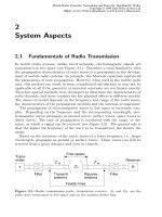
As illustrated in Figure 3.7, UTRAN is composed of a collection of Radio Network Subsys-
tems (RNS), each one connected to the core network through the so-called Iu reference point.
An RNS is responsible for managing the radio resources allocated to a number of cells and for
the transmission/reception in these cells. Every RNS consists of one Radio Network Control-
ler (RNC) and one or more Node-Bs. As shown in Figure 3.7, the reference point connecting
two RNCs is referred to as Iur, while the reference point connecting an RNC with a Node-B is
referred to as Iub. Each Node-B is controlled by only one RNC and it supports the physical
wireless interface with the mobile terminal, i.e. the Uu interface. As explained in Chapter 2,
the Uu interface is based on W-CDMA technology and it supports either Frequency Division
Duplex (FDD) mode or Time Division Duplex (TDD) mode.
Each RNC is assigned a pool of radio resources (for example frequencies, CDMA codes,
Network Architecture 169
etc.) and is responsible for managing those radio resources and allocating them to the mobile
users on a demand basis. Each UE connected to UTRAN is served by a specific RNC, which
is called the Serving RNC (SRNC). The SRNS controls the signalling connection between
the UE and the UTRAN and it also controls the Iu signalling connection for this UE.
Formally, the signalling connection between the UE and the UTRAN is called the RRC
connection, because the signalling protocol between the UE and the SRNC and the RRC
protocol [28].
The RNC that controls a specific set of UTRAN access points, i.e. one or more Node-Bs,
serves as the Controlling RNC (CRNC) for these Node-Bs. There is only one CRNC for any
Node-B and that CRNC has the overall control of the logical resources of that Node-B. In
general, an RRC connection originates at the UE, passes transparently through a Node-B and
its CRNC and terminates at the SRNC. The SRNC and the CRNC may or may not be
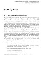
implemented in the same RNC node. Figure 3.8(a) shows a situation where the CRNC of
the illustrated Node-B and the SRNC of the UE correspond to the same RNC node. On the
contrary, Figure 3.8(b) shows another situation where the CRNC of the illustrated Node-B
and the SRNC of the UE correspond to different RNC nodes.
It is clear that the role of controlling RNC makes sense only in connection with a specific
Node-B, while the role of Serving RNC makes sense only in connection with a specific UE. In
Figure 3.8(b) the CRNC of Node-B serves as a Drift RNC (DRNC) with respect to the UE. In
general, a DRNC is the role an RNC can take with respect to a specific RRC connection
Broadband Wireless Mobile: 3G and Beyond170
Figure 3.7 Network schematic diagram
between a UE and UTRAN. An RNC that supports the SRNC with radio resources when the
connection between the UTRAN and the UE need to use cell(s) controlled by this RNC, is
referred to as DRNC.
In this chapter, the UTRAN Iu, Iub and Iur interfaces are collectively referred to as Ix
interfaces. Below, we describe the general architectural aspects of the Ix interfaces. The
architectural aspects of the Uu interface are presented in Chapter 2.
3.4.1.1 Architecture of UTRAN Ix interfaces
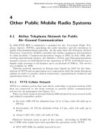
Functionally, the architecture of UTRAN Ix interfaces is decomposed into two layers, the
Radio-Network Layer (RNL) and the Transport-Network Layer (TNL). This is illustrated in
Figure 3.9. The Radio-Network layer is associated with UTRAN-specific signalling and user-
data protocols used between UTRAN nodes, while the Transport-Network layer is associated
with the transport mechanisms used to transport information (either signalling or user data)
between UTRAN nodes. Ideally, these two layers are completely independent and, therefore,
the UTRAN-specific protocols can be implemented over several transport mechanisms. For
instance, one operator may choose to use ATM technology in the Transport-Network layer,
while another one may choose IP technology. The UTRAN Radio-Network layer has been
specified to be independent of the underlying transport mechanisms and thus any transport
mechanism can be used in UTRAN, as long as it satisfies the data transmission requirements
(e.g. delay, throughput, etc). In first UMTS releases, the UTRAN Network-Transport layer is
Network Architecture 171
Figure 3.8 The roles of SRNC and CRNC/DRNC.
based on ATM technology, while in later UMTS releases it evolves to also support IP-based
transport [29].
One of the key features of UTRAN is that the transport-network layer in the control-plane
is independent (or logically separated) from the transport-network layer in the user-plane.
This means that the transport mechanisms used to transport signalling are generally different
and separate from the transport mechanisms used to transport user data. The signalling and
data transport mechanisms used across the various interfaces, i.e. across Iub, Iur and Iu, will
be discussed later on, when these interfaces are discussed in more detail.
As already mentioned above, another key feature of UTRAN is that the radio-network
layer and the transport-network layer are fully separated and independent. This effectively
means that the control- and user-plane functions in UTRAN are fully separated from the
underlying transport functions. Therefore, the transport functions and the UTRAN-specific
control- and user-plane functions can evolve independently.
3.4.1.2 Protocol model of Ix interfaces
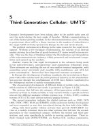
Figure 3.10 illustrates the general model used to describe the protocol architecture of UTRAN
Ix interfaces. This model is composed of a number of horizontal and vertical layers. These
layers are logically independent from each other and this accounts for a highly modular and
expandable architecture. Indeed, each module or layer can be replaced or evolve indepen-
dently from the rest of the modules and, therefore, future requirements can be addressed be
updating only the correct module(s), rather than updating the entire protocol architecture.
In the horizontal direction, there is the radio-network layer and the transport-network layer.
As already explained, the former entails the UTRAN-specific signalling and user data proto-
cols, while the latter entails the underlying transport protocols that transport the UTRAN-
specific protocol data units. All UTRAN-specific issues are handled only by the radio
network layer. The transport network layer is based on standard transport technology, such
as ATM and IP.
In the vertical direction there are two main planes: the control plane and the user plane,
Broadband Wireless Mobile: 3G and Beyond172
Figure 3.9 The concept of transport-network and radio-network layers.
both extending across the radio-network layer and the transport-network layer. The control
plane contains a UTRAN Signalling Protocol (RANAP, RNSAP, or NBAP, which will be
addressed later) and an associated transport mechanism for the transport of the signalling
messages between the UTRAN nodes. As discussed later, the UTRAN Signalling Protocols
are used for setting up data transports (or data bearers) in the radio network layer.
The User plane contains a UTRAN protocol that deal with user-specific data and an
associated transport mechanism for the transport of the user-specific data between UTRAN
nodes. Typical UTRAN protocols that deal with user-specific data (or data streams) include
the Medium Access Control (MAC) protocol and Radio Link Control (RLC) protocol. As
illustrated in Figure 3.10, both Signalling Transport(s) and Data Transport(s) are defined in
the Transport Network User Plane because, from the transport network point of view, they
both transport protocol units that pass transparently through the transport network. In other
words, the transport network treats these protocol units as data units that need to be trans-
ferred without any interpretation. On the other hand, the protocols defined in the Transport
Network Control Plane, are Transport-Signalling protocols (generally referred to as ALCAP
protocols) that generate signalling messages for controlling the transport network. These
messages are interpreted by the transport network and are mainly used to dynamically set
up and release virtual channels within the transport network (of course, when the transport
network supports virtual circuits). As an example, when a new conversational call needs to be
established and the transport network in based on ATM, a new virtual circuit, for example an
AAL2 VC, would need to be established between the Node-B and its CRNC. This AAL2 VC
is created and controlled by means of the transport-signalling protocol.
It should be noted that the Signalling Transport for the UTRAN Signalling Protocol(s) may
or may not be of the same type as the Signalling Transport(s) for the ALCAP.
Network Architecture 173
Figure 3.10 General protocol model of UTRAN interfaces.
The specific details of the protocol architecture that apply to each UTRAN interface will be
discussed later on, when each UTRAN interface is discussed.
3.4.2 UTRAN Functions
Below we summarise some of the most important functions provided by UTRAN. All these
functions are provides by means of several elementary procedures employed in the UTRAN
Ix and Uu interfaces. Some of these elementary procedures will be discussed later.
3.4.2.1 Information broadcasting
In every cell, UTRAN broadcasts information needed by the mobiles to perform specific
tasks, or used to collect specific system information about the network. For example, the
broadcast information includes the network and the cell identities, information for location
registration purposes, specific access rights applicable in a given time, information for trans-
mission power control, information regarding the configuration of the transport channels,
information for cell selection and cell-reselection, the frequency bands used, etc. In addition,
physical-layer information is broadcast to aid mobile acquire synchronisation and decode the
downlink control channels.
3.4.2.2 Security provision
The security mechanisms applied to protect the user data and the signalling information
against malicious attacks, are carried out between the mobile and the UTRAN. In particular,
the UTRAN is responsible for setting up the security mode before any sensitive data is
communicated. In the context of security both ciphering and integrity protection are
provided.
3.4.2.3 Mobility management
The main mobility management functionality required for a mobile in CONNECTED mode is
provided by the UTRAN. For this mobility management the following procedures are
provided:
† Radio measurements: The quality of the radio environment provided to a mobile is
calculated by means of specific radio measurements, taken on the current and the neigh-
boring cells. Typical measurements include the signal strength and the estimated bit error
rate of the current and the neighboring cells, the estimation of the propagation environ-
ment, the received interference level, the Doppler shift, etc.
† Handover decision: From the gathered radio measurements the UTRAN estimates the
quality of the current radio channel and the quality of the neighboring radio channels.
Then it compares the overall quality of service provided with the current radio channel
with the requested limits and with the estimated quality of service of the neighboring cells.
Depending on the outcome of this comparison, the UTRAN may activate the handover
procedure or the macro-diversity procedureand transfer the communication path to
another radio channel in another cell. In addition, the UTRAN may activate the handover
Broadband Wireless Mobile: 3G and Beyond174
procedure to balance the traffic loading between several radio cells. In such cases, a mobile
is commanded to move to a neighboring cell, which is less loaded than the current cell and
which can also provides accepTable 3.quality of service.
† Macro-diversity procedure: Before a mobile is handed over to another radio channel the
macro-diversity mode may be activated. In this mode, the mobile is assigned an additional
radio channel, possibly in another cell, to support the same call. Therefore, the information
transmitted by the mobile is simultaneously transmitted on two radio channels. In addition,
the downlink information is transmitted to the mobile by two different radio channels. For
this macro-diversity technique to work, the UTRAN needs to carry out a macro-diversity
combining/splitting function, which combines the two uplink streams into one and splits
the downlink stream into two, one for each downlink radio channel.
† Handover procedure: This procedure is executed when the current call needs to be
switched to another radio channel, which is considered more appropriate. The handover
procedure is decomposed into several phases. First, a handover initiation is executed,
which identifies the need for handover to the related elements. These elements will
need to take some action in order to realise the handover. Then, the handover resource
allocation takes place wherein the some new resources are allocated and activated to
support the call after the handover. Subsequently, the handover execution is carried out
wherein the mobile is commanded to switch to the new channel. When the mobile actually
changes channel, the call is switched to the new path, which has already been activated
during the handover resource allocation phase. Finally, the handover completiontakes
place wherein the old resources, which supported the call before the handover, are
released. It should be noted that, a handover could be hard or soft. A soft handover initiates
with the activation of the macro-diversity procedure
† Inter-system handover: This procedure enables the handover between radio access
networks that support different radio access technologies, e.g. between a UTRAN and a
GSM BSS.
† SRNS relocation: This procedure is typically executed after an inter-RNS soft handover.
In such cases, the role of the serving RNS needs to be transferred to another RNS in order
to avoid the inefficient resources utilisation within the UTRAN. The SRNS relocation
implies that the Iu interface connection point is relocated from one RNS to another.
3.4.2.4 Radio resource management
The radio resource management is concerned with the allocation and maintenance of radio
communication resources. The allocation procedure encompasses:
† the selection of some communication resources from a pool of resources, and
† the signalling procedures to allocate the selected resources to the mobile that requested for
them.
The maintenance procedure aims to guarantee that the allocated communication resources
will provide the requested quality of service. This procedure is very important in mobile
communications systems where the radio environment is subject to continuous changes and
to interference. In a sense, the radio resource management entity maintains a pool of commu-
nications resources and receives requests for allocation of new resources or release of already
Network Architecture 175
used resources. These requests may originate from the users, who request new calls or release
established calls, or from the maintenance process, which modifies the resources allocated to
a user to guarantee accepTable 3.communications quality. Some functions related to radio
resource management are listed below:
† radio bearer connection setup and release;
† allocation and de-allocation of physical radio channels;
† rf power control and setting;
† radio channel coding control and setting.
† In the following two sections we identify two important aspects of the UTRAN:
† The protocol architecture that provides for the separation of the control and the user planes
in UTRAN, and
† the levels of association between the UE and the UTRAN.
3.4.3 Control and User Plane Separation in UTRAN
Figure 3.11 illustrates the protocol architecture between the UE and the SRNC. This figure
hides any details pertaining to Iub and Iur interfaces. However, it is implicitly assumed that
these interfaces also support separate protocol stacks for the control and the user planes. On
the UE side, the NAS signalling messages (i.e. signalling messages for the CN) is handled by
the RRC protocol, whereas the user-data information is handled by the PDCP protocol. These
protocols, along with the RLC, MAC and the L1 layer are discussed in Chapter 2. On the
SRNC side, the NAS signalling messages are relayed from the RRC to the RANAP and
subsequently transported to the appropriate CN domain through the Iu signalling transport
layer. The user data is relayed from the PDCP layer to the GTP-U layer and subsequently to
the appropriate CN domain through the Iu data transport layer. The details of the Iu signalling
transport and Iu data transport, as well as the details of RANAP, will be discussed later on, in
the context of the Iu protocol architecture discussion.
Broadband Wireless Mobile: 3G and Beyond176
Figure 3.11 The separation of user-plane and control-plane in UTRAN.
It is evident that the control-plane and user-plane transmissions pass through different and
separate protocol stacks in each UTRAN node. In addition, in the UTRAN transport
networks, which are typically based on ATM technology, there are different ATM virtual
circuits for the control and user plane traffic. Usually, the virtual circuits carrying control
plane information are given priority with respect to the other virtual circuits.
3.4.4 UE–UTRAN Association
The level of association between a UE and the UTRAN depends on whether there is a
signalling connection between the UE and the UTRAN. When such a signalling connection
exists, the mobile is formally termed to be in UTRAN-CONNECTED mode. Otherwise,
when no such signalling connection exists, the mobile is in UTRAN-IDLE mode.
In UTRAN-IDLE mode, there is virtually no association between the UTRAN and the UE.
In fact, from UTRAN’s point of view, the UE does not exist, that is, there is no RRC
connection established (see Chapter 2). In this mode, the UE cannot start uplink transmission
and it is not assigned any downlink radio resources. The UE merely camps on a UTRAN cell
and decodes some downlink information, such as system configuration and access informa-
tion. If the UE has previously registered to a CN domain, then it also decodes the broadcast
paging information for identifying potential page messages for it. In general, a UE in
UTRAN-IDLE mode performs the cell select and reselect procedures and all the other
procedures specified in TS 25.304 [30] and in TS 23.122 [31].
The UTRAN-CONNECTED mode is entered as soon as the RRC connection is estab-
lished. In such situations, the UE establishes an association with the UTRAN and it is
assigned a Radio Network Temporary Identity (RNTI) to be used as UE identity on the
common transport channels. In UTRAN-CONNECTED mode the UE is always in one of
the four following RRC states: CELL_DCH, CELL_FACH, CELL_PCH and URA_PCH.
The RRC state of the UE depends on the UE level of activity on the radio interface and on the
requested quality of service. Typically, in the CELL_DCH state dedicated downlink and
uplink resources are allocated to UE, for instance, to support a conversational call. In the
CELL_FACH state, downlink and uplink activity is possible for the UE but no dedicated
radio resources are allocated and, therefore, the UE uses the uplink and downlink common
transport channels (see Chapter 2). These channels provide an effective means of multiplex-
ing a large number of UEs, which are not engaged in calls with real-time requirements. In the
CELL_FACH state the UE monitors a downlink common transport channel and receives any
protocol units that contain its RNTI in the address identifier. Typically, a UE that runs a web
application could be in CELL_FACH state, rather than in CELL_DCH state. In CELL_PCH
and URA_PCH states, no uplink and downlink resources are allocated to the UE and, conse-
quently, no uplink transmission is possible. In these states, the UE decodes the broadcast
information and monitors the appropriate paging channels. The difference between the
CELL_PCH and the URA_PCH states is that in CELL_PCH the position of the UE is
known to the UTRAN at the cell level, whereas in URA_PCH the position of the UE is
known to the UTRAN at the UTRAN Registration Area (URA) level.
When a new RRC connection is established and the UE enters the UTRAN-CONNECTED
mode, the UE is allocated radio resources based on the type of the requested service. Typi-
cally, for conversational and streaming type of calls the UE is assigned dedicated resources
and therefore is in CELL_DCH state. On the other hand, for background types of calls the UE
Network Architecture 177
may be assigned common uplink and downlink radio resources and therefore be in CELL_-
FACH state. Typically, a UE in CELL_FACH state may transit to CELL_PCH and subse-
quently in URA_PCH state when it is inactive for long time duration.
The UE leaves the UTRAN-CONNECTED mode and returns to the UTRAN-IDLE mode
as soon as the RRC connection is released.
3.4.5 The Uu Interface
As already mentioned, this interface is based on the W-CDMA technology. This technology
is used mainly as a radio multiplexing technology, which deals with the way the radio
resources are divided and allocated to several mobile users. However, W-CDMA also speci-
fies some aspects related to the radio transmission technology. In particular, the radio trans-
mission technology should be based on spread spectrum techniques. This is in contrast with
other multiplexing technologies, such as TDMA and FDMA, which typically do not impose
any particular requirements to the radio transmission scheme. The details of the Uu interface
are provided in Chapter 2.
3.4.6 The Iu Interface
As we have already seen, the Iu interface is used to connect UTRAN or GERAN to CN.
Strictly speaking, Iu is not an interface. This is because the term interfaceis typically used to
refer to a point-to-point connection, whereas, Iu is rarely (if ever) configured as a point-to-
point connection. For this reason, the interconnection between the UTRAN and the CN is
referred to in the specifications as Iu reference point. Nevertheless, it is customary (and more
convenient) to also use the term Iu interface, although it is not strictly correct. In this chapter,
we use the terms interface and reference point interchangeably.
As depicted in Figure 3.12, the Iu interface is logically divided into two interfaces: Iu-cs
and Iu-ps. The Iu-cs refers to the logical connection between the RAN and the CS domain,
whereas the Iu-ps refers to the logical connection between the RAN and the PS domain. It is
important to note that the signalling procedures across these two logical interfaces are
identical, i.e. there is a common signalling protocol, called Radio Access Network Applica-
tion Part (RANAP). However, the user-plane protocols are different in Iu-cs and Iu-ps.
The Iu interface has been specified so as to satisfy the following requirements:
† The Iu must support all service capabilities offered to UMTS users, including:
– dedicated circuits, especially for voice;
– best-effort packet services (e.g. Internet/IP);
– real-time multimedia services requiring a higher degree of QoS (CS/PS based);
– UMTS signalling and backward compatibility towards GSM signalling scheme.
† The Iu must support transfer of transparent non-access signalling between the UE and the
CN.
† The Iu must support separation of each UE on the protocol level.
† The Iu must support procedures to establish, maintain and release various types of Iu
bearers.
† The Iu must support procedures for Intersystem handover.
Broadband Wireless Mobile: 3G and Beyond178
In the rest of this section we will discuss the key features of the Iu interface, the protocol
architecture used over the Iu interface and the signalling procedures across this interface.
3.4.7 Key Features of Iu Interface
3.4.7.1 Independence from the RAN technology
In contrast to previous RAN-CN interface technologies (like the Gb interface), Iu interface
is independent of the particular features of a given RAN. In this sense, the core network needs
to know nothing about the structure of the RAN and the corresponding technology used. To
further elaborate on this, we consider the following example. Assume, for instance, that the
core network needs to send a signalling message to a particular mobile. Therefore, the core
network will send a message to the RAN along with some addressing information that will
identify the target mobile. Clearly, if the addressing information contains parameters such as
the target site id, the target cell id, the id of the target protocol within the mobile, etc., then the
core network is bound to using RAN-specific parameters and concepts. In this case, if the
RAN technology is modified, corresponding modifications will be required in the core
network to cope with the change of parameters and change of parameter semantics. If, on
the other hand, the addressing information contains only a generic user identifier, the core
network is made independent of the RAN. In this case, the same core network can be
connected to several RANs, each one possibly based on different RAN technology.
3.4.7.2 Independence between the transport network and radio access network
As indicated in Figure 3.13(a), the radio access network is typically connected to the core
Network Architecture 179
Figure 3.12 Iu interface logical configuration.
network through a transport network. In general, the latter can be based on ATM, IP or any
other technology. Having this in mind, we can logically divide the protocol architecture
across Iu interface into two layers: the transport network layer or transport stratum and the
radio network layer or radio stratum (see Figure 3.13(b)). This division is consistent with the
aforementioned separation of UTRAN architecture into the radio network layer and the
transport network layer (see section 3.4.1). The transport stratum depends on the architecture
of the transport network, while the radio stratum depends on the architecture of the radio
access network (e.g. UTRAN). In the control plane the radio stratum is composed by the
RANAP protocol, while in the user plane, it is composed by the appropriate user plane
protocols of the CS and PS domains. The functionality of the transport stratum corresponds
to the functionality of the four first layers of the OSI model, i.e. physical, data link, network,
and transport. This means that the transport stratum implements procedures such as sequen-
cing, fragmentation/reassembly, error checking, data retransmission, flow control, etc. Well-
known protocols that provide such functionality include TCP and UDP.
One key feature of Iu interface is that the transport and radio strata are independent to each
other. The goal of this independence is to make it feasible to:
† evolve transport and radio network technologies independently of each other, and
† use the transport technology that suits the operator’s preferences.
Broadband Wireless Mobile: 3G and Beyond180
Figure 3.13 Typical physical implementation of Iu. (b) The model of Iu functional strata.
3.4.7.3 Separation between control-plane traffic (i.e. signalling) and user-plane traffic
Iu interface satisfies one of the fundamental principles of 3G systems: the separation between
the control-plane traffic and the user-plane traffic. This means that the control-plane trafficis
transported by using protocols and transport channels that are different and independent from
the corresponding protocols and channels used to transport the user-plane traffic. For
instance, when the transport technology is based on ATM, different virtual circuits could
be used for control and user plane traffic. As we have already discussed, the separation of
control and user plane is applied in the entire UMTS architecture and not only to Iu interface.
By taking into account the last two headings, the generic architecture of Iu-cs and Iu-ps
interfaces in the control and user plane can be illustrated as in Figure 3.14. Observe that Iu-cs
and Iu-ps share a common architecture in the control plane, whereas they feature distinct
architectures in the user plane. In the following section we explain in more detail these
architectures.
3.4.8 Protocol Architecture across Iu
As outlined in the previous section, across the Iu interface the transport stratum used to
transport control-plane messages could be different from the transport stratum used to trans-
port user-plane data. In other words, the transport technology could be different between the
user-plane and the control-plane. In the following two subsections we discuss the protocol
architecture of the transport stratum as used in the control and user planes. This discussion
will be part of the discussion of the overall protocol architecture employed across the Iu-cs
and Iu-ps interfaces.
Network Architecture 181
Figure 3.14 General protocol architecture of Iu logical interfaces.
3.4.8.1 Protocol Architecture across Iu-cs
Figure 3.15 illustrates the protocol architecture employed across the Iu-cs interface. In the
vertical direction, we distinguish the control plane and the user plane. These planes include
the protocol stacks used to transfer network control messages (i.e. signalling) and user data
respectively. In the horizontal direction, we distinguish the radio stratum and the transport
stratum. The transport stratum is typically based on ATM technology and is merely used to
facilitate the reliable transport of upper-layer messages (both user-plane and control-plane)
between network nodes. On the other hand, in the radio stratum we find the protocols, which
are specific to the RAN technology, and are used (1) to implement the Iu signalling proce-
dures (in the control plane) and (2) to process the user data (in the user plane).
As indicated in Figure 3.15, the user-plane traffic across Iu-cs interface is supported over
the ATM Adaptation Layer 2 (AAL2) [42]. This means that each call towards the CS domain
is supported by a specific AAL2 virtual circuit, which is set up before the call is established
and is configured to match the requested QoS profile. In order to dynamically set up and
release AAL2 virtual circuits, there is a need for a control plane in the transport stratum. This
plane is depicted in the middle of Figure 3.15 and is referred to as transport stratum control
plane.
The AAL2 signalling protocol, which is used for establishing AAL2 connections towards
the CS domain, is specified in ITU-T recommendation Q.2630.1 [43]. The protocols below
Q.2630.1 develop a particular transport bearer, suitable for transporting the Q.2630.1 signal-
ling messages. Q.2150.1 [44] is referred to as ‘ATM Adaptation Layer-Signalling Transport
Converter for the MTP3b’ and provides the necessary adaptation functions for operating
Q.2630.1 over the MTP3b layer.
Broadband Wireless Mobile: 3G and Beyond182
Figure 3.15 Iu-cs protocol architecture.
MTP3b provides message routing, discrimination and distribution (for point-to-point link
only), signalling link management load sharing and changeover/back between links within
one link-set.
The following three sub-layers, SSCF-NNI [39], SSCOP [38] and AAL5 [41], consist the
SAAL-NNI, i.e. the signalling ATM Adaptation Layer for Network-to-Network Interface.
The Service-Specific Co-ordination Function (SSCF)
maps the requirements of the above layer to the requirements of SSCOP. It also provides
SAAL connection management, link status and remote processor status mechanisms. Further
details are provided in ITU-T’s recommendation Q.2140 [39].
The Service Specific Co-ordination Protocol (SSCOP) is a peer-to-peer protocol, which
provides mechanisms for the establishment and release of connections and the reliable
exchange of signalling information between signalling entities. In particular, SSCOP
provides the following functions:
† transfer of messages with sequence integrity;
† error correction by selective retransmission;
† flow control;
† connection control;
† error reporting to layer management;
† connection maintenance in the prolonged absence of data transfer;
† local data retrieval by the user;
† error detection of protocol control information, and
† status reporting.
AAL5 is the ATM Adaptation Layer 5 and is specified in I.363.5 [41]. It is a simple
adaptation layer that receives a block of data from the upper layer and
† appends a trailer, which includes a length indicator and a CRC,
† if necessary, appends some bits to make the length of the whole block plus the trailer an
integral of 48 (each ATM cell carries a payload of 48 octets), and
† segments the resulted AAL5 block into an integral number of ATM cells, which are sent to
the lower layer for transmission.
At the receiving side, the AAL5 reassembles all the ATM cells belonging to the same
upper-layer block, removes any padding information and checks the CRC to identify poten-
tial errors. Blocks that pass the CRC check are forwarded to the upper layer.
As shown in Figure 3.15, the signalling transport, i.e. the protocol stack used to transport
the signalling (RANAP) messages, is composed of the Signalling Connection Control Part
(SCCP) [32–36], MTP3b and SAAL-NNI. SCCP is the main signalling protocol used in SS7
signalling networks. It operates on top of MTP3 or MTP3b and enhances the functions
provided by the lower layers (e.g. MTP3).
The key enhancements provided by SCCP are outlined below:
Connectionless signalling transport services
This type of service transports messages between SCCP peers with no flow control, no
sequencing, and no segmentation. Therefore, the correct delivery of messages is not guaran-
teed. The maximum size of a message (or, a network service data unit, NSDU) can be up to
Network Architecture 183
255 octets, when addressing is not by global title. Across Iu interface, the connectionless
service of SCCP is used to implement the Iu general control services and the Iu notification
services. The general control services are services related to the whole Iu interface instance
between an RNC and the CN. For instance, the Reset procedure used to initialise the UTRAN
in the event of a failure in the CN or vice versa, is one of the procedures used to implement the
general control services. On the other hand, the notification services are services related to a
specific mobile or all the mobiles in a specified area. A typical example is the paging
procedure (see below), which is one of the procedures used to implement the Iu notification
service.
Connection-oriented signaling transport services
With this type of service, the SCCP messages exchanged between two SCCP peers are subject
to sequencing, retransmission and segmentation. In this way, a reliable and in-sequence
signalling transport is established. Across Iu interface, the SCCP connection-oriented
services are used to support the Iu dedicated control services, which are services related
to one single mobile. Procedures used to implement the dedicated control services include the
relocation procedure, the Iu release procedure, the direct transfer procedure, etc. Details on
these procedures are provided in subsequent sections.
Enhanced addressing capability
The SCCP gives its users the option to use a global title (e.g. an E.164 number) as an address
that uniquely identifies an application residing in a remote SS7 node. In such cases, SCCP
performs a translation function (referred to as Global Title Translation, GTT), which trans-
lates the global title into an SS7 point code (PC) and subsystem number (SSN). The PC, SSN
pair are subsequently used by MTP3 to route the message to the appropriate SS7 node. By
using global titles as an addressing scheme, the SCCP users do not need to know the exact
SS7 addresses (e.g. PC, SSN) of the entities they want to communicate with.
In addition to the global title support, SCCP can address up to 255 users above it (by
employing individuals SSNs), whereas MTP can only address up to 16 MTP users. RANAP is
one of the SCCP users and it is assigned the SSN number 142.
From the above discussion we conclude that the physical implementation of the Iu-cs
interface could be as the one illustrated in Figure 3.16. In this figure, there are N AAL2
virtual circuits (VCs), each one used to support an individual user call towards the CS
domain. In addition, there are two preconfigured AAL5 VCs:
† One transport signalling VC, which typically has a virtual path identifier of 0 and a virtual
channel identifier of 5. This VC is used by the transport stratum control plane, that is, it is
used to transfer Q.2630.1 messages to and from the ATM network. These messages are
used to dynamically manage the AAL2 VCs.
† One radio signalling VC that transports signalling (i.e. RANAP) messages between the
RNC and the MSC.
3.4.8.2 Protocol architecture across Iu-ps
Figure 3.17 illustrates the protocol architecture used across the Iu-ps. When comparing this
Broadband Wireless Mobile: 3G and Beyond184
Network Architecture 185
Figure 3.16 Typical ATM VCs on Iu-cs interface.
Figure 3.17 Protocol architecture across Iu-ps.
protocol architecture with the corresponding protocol architecture of Iu-cs (see Figure 3.16),
three observations can be made:
The user-plane transport in Iu-ps is not based on AAL2, but on AAL5
Also, since on top of AAL5 there is IP, UDP and GTP-U, we conclude that user data across
Iu-ps is routed with IP and is transported in GTP-U tunnels. Figure 3.18 explains schema-
tically how data is transferred over the Iu-ps. As shown in Figure 3.18(a), the AAL5/ATM
layers are used to establish a virtual channel between the RNC and the PS domain through
the ATM network. This virtual circuit is used to multiplex all IP traffic. In the PS domain
the AAL5 VC typically terminates to an IP router, which routes the IP packets to and from
the correct SGSN in the PS backbone. As shown in Figure 3.18(b), the IP traffic between the
RNC and the SGSN is logically decomposed into a number of individual GTP-U tunnels.
These tunnels are managed by the RANAP protocol, which contains appropriate procedures
to setup new tunnels, or release already established tunnels. In particular, a new GTP-U
tunnel is established when a new RAB is established (see section 0 for details). The GTP-U
tunnel each packet belongs to is identified by the tunnel endpoint identifier that is included
in the GTP-U header. One mobile may utilise one or more GTP-U tunnels, each one
corresponding to a different set of protocol parameters (e.g. IP address) and/or QoS para-
meters.
Broadband Wireless Mobile: 3G and Beyond186
Figure 3.18 AAL5/ATM layers are used to establish VCs between the RNC and the PS domain. (b)
The concept of GTP-U tunnels.