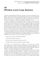
Tài liệu Điện thoại di động mạng lưới Radio P3 pptx
Bạn đang xem bản rút gọn của tài liệu. Xem và tải ngay bản đầy đủ của tài liệu tại đây (2.15 MB, 179 trang )
3
GSM System
∗
3.1 The GSM Recommendation
The early 1980s were marked by the development of a number of national
and incompatible radio networks in Europe; see Table 1.2 and Figure 1.3.
The seven different mobile radio networks made the prospect of the mobile
telephone unattractive to many potential customers because of high tariffs
and equipment costs.
For this reason, at its general meeting in Vienna in June 1982, CEPT (see
Appendix B.2.2) decided to develop and standardize a Pan-European cellular
mobile radio network. The aim was for the new system to operate in the
900 MHz frequency band allocated to land mobile radio.
A working group, called Group Sp´ecial Mobile (GSM), was set up under
the direction of CEPT. There were no guidelines on how the new mobile radio
system was to transmit analogue or digital speech and data. The decision to
develop a digital GSM network was not made until the development stage. But
it was agreed from the beginning that the system being planned—called the
GSM mobile radio system after the working group that developed it—should
incorporate and consider new technology from the area of telecommunications,
such as ITU-T Signalling System No. 7, ISDN and the ISO/OSI reference
model.
Six working groups and three supporting groups were formed to cope with
the enormity of the standardization work. The tasks of the different GSM
working groups are listed in Table 3.1.
The GSM objectives for its Public Land Mobile Network (PLMN) were to
offer [1]:
• A broad offering of speech and data services
• Compatibility with the wireline networks (ISDN, telephone networks,
data networks) using standardized interfaces
• Cross-border system access for all mobile phone users
• Automatic roaming and handover
• Highly efficient use of frequency spectrum
∗
With the collaboration of Peter Decker and Christian Wietfeld
Mobile Radio Networks: Networking and Protocols. Bernhard H. Walke
Copyright ©1999 John Wiley & Sons Ltd
ISBNs: 0-471-97595-8 (Hardback); 0-470-84193-1 (Electronic)
122 3 GSM System
Table 3.1: Tasks of the GSM working groups
GSM working groups Tasks
Working Party 1 Definition of services and service quality
Working Party 2 Definition of access, modulation and coding proce-
dures
Working Party 3 Definition of protocols for signalling between mo-
bile stations, mobile functions and fixed communi-
cations networks
Working Party 4 Specification of data services
Working Party 5 Development of UMTS
Working Party 6 Specification of network management features
Speech Coder Experts
Group (SCEG)
Definition of technique for digitization of speech at
a low bit rate
Security Experts Group
(SEG)
Responsibility for all aspects of security (access,
coding, authentication)
Satellite Earth Systems
(SES)
Support of GSM through satellite systems
Table 3.2: Original timetable for introducing the GSM system
Date Phase
February 1987 Invitation for tenders
Mid 1988 Letters of Intent
End 1988 Validation of interfaces
Mid 1990 System validation
March 1991 Start of equipment deliveries
June 1991 Operation of first base station
1993 Coverage to metropolitan areas and major roads
since 1995 Area-wide operation
• Support of different types of mobile terminal equipment (e.g., car,
portable and hand-held telephones)
• Digital transmission of signalling as well as of user information
• Supplier-independence
• Low costs for infrastructure and terminal equipment
The GSM group tested a number of prototypes for digital cellular radio
systems, and in 1987 decided on a standard that combined the best charac-
teristics of different systems. A timetable drawn up at the same time for the
implementation of the plan gained the full support of the European Union
(EU) (see Table 3.2).
3.1 The GSM Recommendation 123
Table 3.3: The series of the GSM recommendation
Series Content
00 Preamble
01 General aspects, terminology and service introduction phases of the
GSM Public Land Mobile Network (PLMN)
02 Definition of telecommunications services, technical aspects concerning
tariffs and international billing procedures
03 Definition of network functions such as traffic routing, handover, secu-
rity issues relating to network access, network planning
04 Description and definition of protocols and interfaces between mobile
station (MS) and base station (BS)
05 Radio path functions such as multiplexing, channel coding, synchro-
nization and interleaving
06 Speech processing and speech coding functions
07 Adaptation of terminal equipment and transmission rates
08 Description of interface functions between base station system (BSS)
and mobile services switching centre (MSC)
09 Definition of interworking functions (IWF) between one or more GSM
networks and different fixed networks
11 Equipment specifications and type approval guidelines
12 Operation and maintenance of a GSM network
By 1987, comprehensive guidelines for the new digital mobile radio system
had already been established by the GSM group. By signing the Memoran-
dum of Understanding on the Introduction of the Pan-European Digital Mo-
bile Communication Service (MoU) on 7 September 1987, the 13 participating
countries confirmed their commitment to introducing mobile radio based on
the recommendations of the GSM.
Later, in March 1989, the GSM working party was taken over by ETSI (see
Appendix B.2.3), and since 1991 has been called the Special Mobile Group
(SMG). Today the abbreviation GSM stands for Global System for Mobile
Communications, thereby underlining its claim as a worldwide standard.
In the meantime all the European countries as well as a large number of
other countries in the world have signed the GSM-MoU agreement and have
developed or will be developing mobile radio systems in their countries based
on the GSM recommendations (see Table 3.39).
The planned official start to the GSM system was delayed by one year. Only
five countries were in a position to undertake test operations on 1st July 1991.
The reason for the delay was the level of complexity of the digital network and
its components, which is reflected in the voluminous specifications which today
total around 8000 pages. In 1990 alone another 500 GSM change requests were
passed. The entire set of GSM recommendations is divided into 13 series,
which cover different aspects of the GSM system, as shown in Table 3.3 (see
also Appendix E).
124 3 GSM System
The GSM recommendations contain detailed specifications for the radio in-
terface which in part are borrowed from the concepts for the analogue national
cellular standard and ITU-T Rec. X.25. However, large parts of the radio in-
terface are specific to the GSM system. Some of the important features of
GSM include:
Frequency band The frequency range between 935 and 960 MHz is used as
the base station transmitting frequency (downlink) and the frequencies
between 890 and 915 MHz are used as the base station receiving fre-
quency (uplink). The carrier frequencies of the FDM radio channels
have 200 kHz channel spacing in each band, thus providing 124 FDM
channels. With time-division multiplexing (TDM), eight communica-
tions channels (time slots) are supported per FDM channel.
Handover Handover from one base station to another is a mechanism that
allows the connection quality of calls between users to be maintained,
interference to be minimized and traffic distribution to be controlled. In
addition, procedures are defined for the re-establishment of a connection
if a handover fails.
Power control In the area over 30 dB the equipment of the mobile user and
of the base station controls power in 2 dB steps in order to minimize
interference.
Discontinuous transmission (DTX) GSM offers the option of discontinuous
transmission of speech using voice activity detectors. With DTX, trans-
mitter battery power is only used when speech or data is being trans-
mitted, which minimizes interference and improves the utilization of
frequency spectrum.
Synchronization Depending on the system, all frequencies and times are syn-
chronized with a highly stable (0.005 ppm) reference, which can be cou-
pled with a frequency normal.
The following features distinquish GSM from other European mobile radio
systems:
• Europe-wide coverage
• Europe-wide standardization
• digital radio transmission
• extensive ISDN compatibility
• protection against eavesdropping
• support of data services
GSM is regarded as an important advance compared with predecessor sys-
tems and is considered to be representative of so-called 2nd-generation sys-
tems. Along with important technological advances (particularly the intro-
duction of digital transmission technology), the standardization of the inter-
faces between subsystems in GSM has provided manufacturers and network
operators flexibility in their development work and configurations.
3.2 The Architecture of the GSM System 125
U
m
A
bis
(NSS)
Switching Subsystem
Network and
(OSS)
Subsystem
Operation
MS
MS
EIR
OMC
AuC
HLR
VLR
BSC
BTS
BTS
BSC
MSC
BTS
MS
A
O
BTS-BSC PSTN
ISDN, PDN
(BSS)
Base Station Subsystem
Radio Subsystem
O (see below)
Points of reference:
Interface to
Transition to
Interface
Radio Interface
other Networks
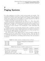
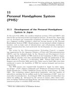
Figure 3.1: Functional architecture of the GSM mobile radio network
3.2 The Architecture of the GSM System
3.2.1 Functional Structure of the GSM System
In GSM specification 1.02 the GSM system is divided into the following sub-
systems [20]:
• Radio subsystem (RSS)
• Network and switching subsystem (NSS) and
• Operation subsystem (OSS)
These subsystems and their components are represented in the simplified
version of the functional architecture in Figure 3.1.
126 3 GSM System
3.2.1.1 Radio Subsystem
The radio subsystem is made up of the mobile stations (MS) and the Base
station subsystem (BSS).
Mobile station The term mobile radio station (MS) refers to all the physical
equipment of a PLMN user. It includes the mobile terminal and the user
interface that the subscriber needs in order to access PLMN services.
A GSM mobile station consists of two parts. The first part contains all
the hardware and software components relating to the radio interface; the
second part, known as the subscriber identity module (SIM), stores all the
subscriber’s personal data. The SIM is either installed into the terminal or
provided as a smart card, which is about the size of a credit card and has the
function of a key. Once it has been removed from a device, it can only be
used for emergency calls, if the network so allows. A mobile subscriber can
use the SIM to identify himself over any mobile station in the network, and
accordingly a mobile phone can be personalized using the SIM. In addition,
each mobile station has its mobile equipment identity (EI).
The following numbers and identities are assigned for the administration
of each mobile station within a GSM network; see Figure 3.57:
• International Mobile Subscriber Identity (IMSI)
• Temporary Mobile Subscriber Identity (TMSI)
• Mobile Station International ISDN Number (MSISDN)
• Mobile Station Roaming Number (MSRN)
Mobile stations can be installed in automobiles or provided as port-
able/hand-portable devices and, according to GSM Rec. 2.06, are divided
into five different classes depending on the allowable transmitter power; see
Table 3.4.
These classifications also characterize different types of devices: mounted,
portable and hand-portable devices. Equipment for the GSM-900 class 1 (8–
20 W) has not yet been developed. Instead, portable and mounted equipment
is typically found in class 2 (5–8 W). Hand-portable equipment mostly con-
forms with class 4 (0.8–2 W). Class 5 (up to 0.8 W) is also being planned for
hand-portable equipment, but places a considerable strain on cellular radio
signal supply. This is one of the reasons why it is more suitable for urban
environments with small cells, but it is hardly being used anywhere yet. An
MS can have facilities for both voice as well as data transmission.
In addition to the network-dependent radio and protocol functions that
enable access to operation in the network, a mobile station outwardly has at
least one other interface to the mobile subscriber (see Section 3.2.2). It is
intended either for a human user (man–machine interface) or for coupling the
terminal adapter of another terminal, such as a computer or a fax machine or
3.2 The Architecture of the GSM System 127
Table 3.4: Power classes of mobile stations according to GSM or DCS 1800
GSM 900 DCS 1800
Class Max. transmit. Type of device Max. transmit. Type of device
power [W] power [W]
1 20 Mounted 1 Hand-portable
and portable
2 8 Portable and 0.25 Hand-portable
mounted
3 5 Hand-portable − –
4 2 Hand-portable − –
5 0.8 Hand-portable − –
a combination of the two. The GSM specifications leave the conversion and
extent of the interface technique up to the manufacturer.
A user interface usually consists of the following components:
• microphone
• speaker
• LCD display field
• alphanumeric keyboard
• so-called soft keys
Soft keys are function keys used to switch a terminal to different operating
states. They are not assigned a specific function, as is the case with hard
keys, e.g., on a drinks dispenser. Consequently the user must be informed of
the respective function before using the keys.
Soft keys are extremely useful with hand-held mobile phones. The sub-
scriber can use his mobile device with one hand because of the soft key menu
functions that are displayed on the mobile, without having to press key combi-
nations at the same time, as is required with the hard key version of a control
panel.
Unlike the conventional telephone, where the user is identified through
the fixed network connection, radio connections form an anonymous network.
Therefore subscriber identification is a prerequisite in a mobile radio network
alone for operational reasons. The stored subscriber-related data in a SIM
module identifies the subscriber when he checks in, and his location area
is derived from the serving base station—an automatic procedure when the
terminal is used.
In older devices the SIM is installed into the equipment, but the new ap-
proach is to plug it in as a card; there are two versions of this:
• smart card, also called standard SIM card
• plug-in SIM card
128 3 GSM System
The only difference between the two cards is their size. The standard SIM
card is the size of a credit card based on standard ISO 7816, whereas the plug-
in module is smaller in size and based on the GSM Rec. 02.17 [6]. In addition
to their size, the cards are also used differently. Whereas the standard SIM
card can be activitated simply by being inserted into the card slot provided in
the mobile telephone, the smaller module slides into the equipment mounted
on a cut-down card, which involves first removing the battery. The smaller
plug-in SIM card has been successful with hand-held mobile telephones.
The subscriber-related data is stored in the non-volatile memory of the
SIM. It can be changed statistically as well as temporarily. The permanent
data includes the following elements [6]:
• SIM card type
• IC card identification: serial number of the SIM; identifies card holder
at the same time
• SIM service table: list of additional services subscribed
• IMSI (International mobile subscriber identity)
• PIN (Personal identity number)
• PUK (PIN unblocking key)
• Authentification key K
i
Before a SIM card is assigned to a subscriber, it is first initialized with
this data, and only then can the subscriber use the card to check into the
network. On the other hand, the dynamic data, which is permanently updated
when the terminal is switched on, accelerates the checking-in process because
relevant information is already stored centrally and there is no need for it to
be requested from the network. This includes the following data items [6]:
• Location information: consists of a TMSI, a LAI, a periodically changed
location updating timer, and update status
• Ciphering key K
c
for encoding, and its sequence number
• BCCH information: list of carrier frequencies for cell selection during
handover and call setup
• List of blocked PLMNs
• HPLMN search: period of time in which an MS roams the home network
before it tries to check into another network
3.2 The Architecture of the GSM System 129
Other optional data items can be found in [6]. All SIM data is copied in the
memory of the MS only for the duration of the active operating state and then
deleted. Manufacturers of mobile terminals have the option of additionally
providing intermediate storage of less important data, such as short messages
and the last-called telephone number. However, this data can only be called
up if the equipment is turned on again with the same SIM card that was used
for its previous deactivation [6].
PIN Except for emergency calls, mobile equipment can only be operated if
the SIM card has first been activated. This is done by the subscriber punching
in a PIN code, which can be between four and eight digits long, after switching
on the equipment. When the SIM card is provided by the service provider,
the PIN is generally preset with a four-digit number, which the subscriber can
change as often as he likes. After the PIN has been correctly entered, the
network responds and the mobile is automatically checked in.
A PIN can be but should not be disabled, because the subscriber will run
the risk of potential thieves using the mobile free of charge until use of the
card is suspended. Anyone who steals an activated mobile phone can only use
the SIM card fraudulently until the first time the equipment is switched off
or the battery runs out. If an incorrect PIN is inserted three times in a row,
the card will be suspended. The subscriber then needs an unlocking key PUK.
Some cards are available with a second PIN to protect some of the numbers
stored in the card. This specifically protects personal telephone numbers and
names entered on the card from unauthorized access. The security mecha-
nisms and maximum allowable code length of the PIN2 are identical to those
of the PIN [6].
PUK A blocked SIM card can only be released through the use of an PIN
unblocking key PUK. The subscriber is allowed 10 attempts in which to enter
the correct PUK code or else the card will be blocked permanently and can only
be unblocked by the service provider. The PUK is an eight-digit permanent
number that is divulged to the subscriber when he receives the card [6].
3.2.1.2 Base Station Subsystem (BSS)
The BSS comprises all the radio-related functions of the GSM network.
Depending on the radio transmitting and receiving capabilities of the base
transceiver system, which because of limited transmitter power only supplies
coverage to a specific geographical area within the network, radio cells are cre-
ated in which the mobile subscriber is free to roam or communicate. The size
of the individual cells depends on a number of parameters, including char-
acteristics of radio wave propagation, local morphology, and expected user
density in the region.
130 3 GSM System
A BSS uses transceivers and the following hardware and software to enable
it to connect a mobile subscriber to a number in the public telephone network
(PSTN) and allow it to communicate:
• signalling protocols for connection control
• speech codecs (coders/decoders) as well as data-rate adaptation (trans-
coder/rate adapter unit, TRAU) for access to the network
• digital signal transmission for coded data.
These functions already give an indication of some of the other important
tasks of the BSS. Various interfaces have been specified between the BSS and
GSM network elements and other networks for the exchange of information
between subscribers and the GSM network or other networks; see Figure 3.1.
The interface to the mobile subscriber is called the U
m
-interface. It contains
specific parameters for digital radio transmission, such as GMSK modulation,
data rate, status of carrier frequencies in the 900 MHz band and channel grid.
The BSS is connected to the GSM fixed network over the A-interface (familiar
from ISDN) with MSCs, the NSS switching centres that provide the subscriber
connectivity to each other and to the external network. The A-interface like-
wise contains specific digital transmission parameters, including PCM (pulse
code modulation), a 64 kbit/s data rate and a 4 kHz voice bandwidth.
Network availability and quality is established by the network operations
and maintenance centre (OMC) of the GSM operator over an O-interface,
which provides direct access to BSS units.
The elements making up the BSS include:
• Base transceiver station (BTS)
• Base station controller (BSC)
BTS The BTS comprises the transmitting and receiving facilities, including
antennas and all the signalling related to the radio interface. Depending on the
type of antenna used, the BTS supplies one or several cells, so, for example,
sectorized antennas can supply three cells arranged at 120
◦
to each other (see
Chapter 2.4).
In a standardized GSM structure the transcoding and rate adaptation unit
TRAU is part of the BTS. It contains GSM-specific speech coding and decod-
ing as well as rate adaptation for data transmission.
BSC The BSC is responsible for the management of the radio interface
through the BTS, namely for the reservation and the release of radio channels
as well as handover management. Its other tasks include paging and trans-
mitting connection-related signalling data adapted to the A-interface from/to
the MSC.
A BSC generally manages several BTSs, and is linked to the NSS via an
MSC.
3.2 The Architecture of the GSM System 131
3.2.1.3 Network and Switching Subsystem (NSS)
Switching and network-oriented functions are carried out in a Network and
switching subsystem (NSS). It forms the gateway network between the ra-
dio network and the public partner networks (e.g., Public Switched Telephone
Network (PSTN), Integrated Services Digital Network (ISDN), Public Switched
Data Network (PSDN)). In their entirety not only are the elements of an NSS
purely physical components but, more importantly, the switching subsystem
provides a large number of functions that are the responsiblity of the manu-
facturer and network operator to implement appropriately.
The NSS components include the Mobile Services Switching Centre (MSC),
the Home Location Register (HLR) and the Visitor Location Register (VLR).
Mobile services switching centre (MSC) The MSC is a high-performance
digital switching centre that carries out normal switching tasks and manages
the network. Each MSC is usually allocated several base station controllers,
and in the geographical area assigned to it carries out the switching between
mobile radio users and other PLMNs and also forms the link between the
mobile radio network and the wireline networks (PSTN, ISDN, PDN). The
MSC is responsible for all the signalling required for setting up, terminating
and maintaining connections, carried out in accordance with Common Chan-
nel Signalling System No. 7, and mobile radio functions such as call rerouting
when there is strong interference, as part of a handover and the allocation
and deallocation of radio channels.
Transmission functions for data services are supported through the use
of specific interworking functions (IWF) that are integrated into each MSC.
The respective communications channel functions are carried out by facilities
called data service units (DSU). The DSU contains functions such as rate
adaptation, modem and codec of layer 1, and protocol functions of layer 2.
The other tasks of the MSC include the supplementary services familiar
from ISDN, such as call forwarding, call barring, conference calling and call
charging to the user called. The MSC can be envisaged as an ISDN switch-
ing centre that has been expanded to include the necessary mobility-related
switching functions.
Home location register (HLR) All important information (quasi-permanent
static data) relating to each mobile subscriber, including telephone number,
MS identification number, equipment type, subscription basis and supplemen-
tary services, access priorities and authentication key, is stored in the database
referred to as the home location register. Temporary (dynamic) subscriber
data (e.g., current location area (LA) of the mobile station and mobile station
roaming number (MSRN)) that are necessary for setting up a connection are
also stored. When a mobile user leaves his momentary location area (LA),
the temporary data held in the HLR is immediately updated. The home loca-
tion register usually falls under the responsibility of a mobile switching centre
132 3 GSM System
GSM
NSS
BSS
Network operation
and
maintenace
Subscription
management
Mobile
management
equipment
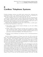
Figure 3.2: Structure of an OSS
(MSC). Each mobile subscriber and his related data are registered in only one
home location register in which all the billing and administrative tasks are
carried out. In many existent GSM networks there is only one HLR being
implemented.
Visitor location register (VLR) The visitor location register is under the
control of an MSC and is used to manage the subscribers who are currently
roaming in the area under the control of the MSC or, more precisely, in one
of possibly several location areas of the MSC. It stores information (e.g., au-
thentication data, international mobile subscriber identity (IMSI), telephone
number, agreed services) transmitted by the responsible HLR for the mobile
users operating in the area under its control, thereby allowing the MSC to
make a connection. The VLR also controls the allocation of roaming numbers
(MSRN) to the mobile stations as well as of the TMSI. A special dialogue up-
dates the VLR if a mobile user moves through several of the MSC’s location
areas. The same procedure applies when there is a change of MSC. The VLR
avoids frequent interrogation of the HLR.
The functions location area update and call setup and the roles played by
the HLR and the VLR in these functions are described in Sections 3.7 and 3.8.
3.2.1.4 Operation Subsystem (OSS)
The operation subsystem in GSM comprises all the important functions for op-
eration and maintenance. The user is only indirectly aware of these functions
through his experience with a smoothly functioning mobile radio network.
The functions of an OSS are allocated to three areas of responsibility (see
Figure 3.2):
• Subscription management
• Network operation and maintenance
• Mobile equipment management
3.2 The Architecture of the GSM System 133
The following network elements are part of the OSS:
• Operation and maintenance centre (OMC)
• Authentication centre (AuC)
• Equipment identity register (EIR)
Subscription management Subscription management is able to authenticate
a GSM user from the personal data stored in the HLR (see Section 3.13.1) and
provide him with the agreed services (subscriber data management). This data
provides the network operator and the service provider with a call-charging
basis.
Subscriber data management The subscriber data is stored and managed
in the HLR; information relating to data security is in the AuC. The HLR
can provide restricted access to elements from other networks, e.g., in order
to allow service providers access to tariff and services data and to ensure
the consistency of data stored in different locations. As has already been
mentioned, the SIM card is a dynamically changeable data storage unit during
the active operation of a mobile station.
Call charging Similarly to ISDN, the mobile radio user is charged for services
used on the basis of so-called call tickets. These call tickets are used for billing
irrespective of where a call is made in the network. The billing location can
be the MSC in which the mobile subscriber is currently active or a gateway
MSC (GMSC) where a communication is connected to an external network.
The HLR only stores call-related data. Call billing is handled by the re-
sponsible OSS subscriber management. At the same time tariff data is also
transmitted between the MSCs or GMSCs and the HLR over the common
channel signalling system no. 7 (SS 7).
Network operation and maintenance The control of network operation and
maintenance tasks uses a separate switching network to connect operating
personnel network elements. The network is based on the concept of TMN
(Telecommunications Management Network) developed by the ITU-T. The
TMN forms an integrated network with its own databases that offer the op-
erator options for monitoring, control and intervention.
The TMN functions are divided into individual layers similar to the network
element functions in the ISO/OSI reference model:
Business management Controls the interaction between network and ser-
vices and provides information about other service and network devel-
opments.
Service management Used for the execution of all contractual aspects of a
service between supplier and customer.
134 3 GSM System
Network management Supports all network elements and helps to activate
functions with similar elements of a network.
Network element management Facilitates access to individual network ele-
ments.
GSM uses standardized concepts for network management, thereby facili-
tating the integration of the network elements of different suppliers.
The TMN has links with defined interfaces to the network elements of the
active network and to the workstation computers of operating personnel. OSS
network elements that are connected to several BSS or MSS units are referred
to as OMCs. A radio OMC, for example, is responsible for several BSCs and
their BTSs.
Mobile equipment management The management of mobile equipment by
the OSS only concerns information about owner and equipment identity,
whereas the MSS coordinates the movements of the equipment, including
roaming, handover and paging. For example, an OSS can search for stolen or
defective equipment using its own database, an EIR, for storing data about
equipment and its ownership (some operators have not established the EIR).
Operation and maintenance centre (OMC) The OMC centrally monitors
and controls the other network elements and guarantees the best possible ser-
vice quality for a network. It relies on services of the network management
and control functions allocated to the network elements by the hierarchical
network management system (TMN). Operator commands are used for inter-
vention into the network elements, while the network management is alerted
of any unexpected occurrences in the network. The OMC is connected to all
network elements over the standardized O-interface (an X.25-interface). The
management functions of the OMC include administration of subscribers and
equipment, billing, and generation of statistical data on the state and the
capacity utilization of network elements.
Authentication centre (AuC) The AuC contains all the information re-
quired to protect a subscriber’s identity, and his mobile communication
against eavesdropping, and his right to use the radio interface. Because the ra-
dio interface is generally susceptible to unauthorized access, special measures
(e.g., authentication key assigned to each subscriber and coding of transmit-
ted information) were undertaken in order to prevent the fraudulent use of
GSM–PLMN connections. Authentication algorithms and encryption codes
are stored in the AuC, and strict rules apply for access to this information
(see Section 3.13).
Equipment identity register (EIR) The EIR is a central database in which
subscriber and equipment numbers (International Mobile Equipment Identity,
3.2 The Architecture of the GSM System 135
TE2
TE2 TA
MT2
MT1
MT1
MT0
TE1
U
m
R
S
Mobile station
R-Interface S-Interface
Figure 3.3: Mobile station network terminations with the reference points R, S,
U
m
IMEI) are stored, and is connected over an interface to the NSS network
elements and the OSS. The database contains a white, a black and a grey list.
The white list contains the IMEI list of valid mobile radio stations; the black
list contains all the IMEIs of stolen or suspended mobile radio stations. The
grey list includes a list of IMEIs for malfunctioning equipment that is not
receiving any services.
3.2.2 Interfaces of the GSM System
3.2.2.1 User Interface of the Mobile Station
A GSM mobile station consists of the terminal equipment (TE) to which the
subscriber has direct access, a terminal adapter (TA) (if required) and a part
that contains the functions shared by all the services and referred to as mobile
termination (MT) in the GSM specifications. The subscriber interface on the
terminal (TE) contains the network termination and the different equipment
functions (see Figure 3.3).
The following mobile network terminations are used:
MT0 (Mobile Termination Type 0) A network termination for the transmis-
sion of speech and data integrating the terminal equipment, the terminal
equipment functions and sometimes a TA.
MT1 (Mobile Termination Type 1) A network termination with an external
ISDN S-interface to which an ISDN terminal (TE1) can be connected.
136 3 GSM System
Conventional terminal equipment (TE2) corresponding to the ITU-T,
V or X-series can be connected to an MT1 through the use of an ISDN
terminal adapter (TA).
MT2 (Mobile Termination Type 2) This is a network termination with an
external R-interface to which conventional terminal equipment corre-
sponding to the ITU-T, V or X-series can be connected.
TE1, TE2 and TA correspond to comparable functional groups of the ISDN
concept. The radio interface that supports ISDN-compatible access over traffic
and signalling channels is located at reference point U
m
.
3.2.2.2 Radio Interface
This is an important interface in the GSM system, and is therefore covered in
detail in Section 3.3.
3.2.2.3 BTS–BSC Interface at Reference Point A
bis
Transmission over the A
bis
-interface (see Figure 3.1) is based on PCM-30 and
64 kbit/s interfaces.
Because PLMN network operators frequently are not also the operators
of the telecommunications networks, a submultiplex technique that transmits
four 16 kbit/s channels over a 64 kbit/s channel was standardized to save on
line costs.
3.2.2.4 BSS–MSC Interface at Reference Point A
Speech and data are transmitted digitally over the A-interface (see Figure 3.1),
over PCM-30 systems based on the ISDN standard (ITU-T-Series G.732). A
PCM-30 system has 30 full-duplex channels at 64 kbit/s, with a transmis-
sion rate of 2.048 Mbit/s full-duplex. Two channels each with 64 kbit/s are
required for synchronization and signalling (D
2
-channel).
3.2.2.5 BSC/MSC–OMC Interface at Reference Point O
The O-interface is based on ITU-T recommendation X.25, which was specified
for the attachment of data terminal equipment to packet-switched networks.
Physically this interface can be implemented over a 64 kbit/s channel. The
option exists to use interfaces of line-switched networks, e.g., V.24bis or X.21.
3.3 The Interface at Reference Point U
m
This radio interface is located between the mobile station (MS) and the rest
of the GSM network. Physically the information flow takes place between the
mobile station and the base transceiver station (BTS). But, viewed logically,
3.3 The Interface at Reference Point U
m
137
1 40 2 3 5 6 7 1 40 2 3 5 6 77
1 40 2 3 5 6 7 1 40 2 3 5 6 77
n
F
1 40 2 3 5 6 7 1 40 2 3 5 6 77
n+1
F
n-1
F
Frequency
Physical channel, characterized through the frequency F and the time slot 0
n+1
0.577 0.577 0.577 0.577 0.577 0.577 0.577 0.577 0.577 0.577 0.577 0.577
Time (ms)
0.577 0.577 0.577
4.615
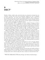
Figure 3.4: Realization of physical channels using FDM and TDM
the mobile stations are communicating with the base station controller (BSC)
and the mobile switching centre (MSC). The gross transmission rate over the
radio interface is 270.833 kbit/s.
3.3.1 Multiplex Structure
Along with voice coding and modulation, multiplexing is also very important.
In the GSM recommendations a combination of frequency-division multiplex-
ing (FDM) and time-division multiplexing (TDM) has been standardized, pro-
viding multiple access by mobile stations to these systems (FDMA, TDMA).
Figure 3.4 shows how a physical channel is produced through a combination
of FDM and TDM (see channel 0 on frequency F
n+1
and Sections 3.3.1.1
and 3.3.1.2).
GSM utilizes the cellular concept, already proven successful in analogue
mobile radio networks, in which a geographical area is divided into planned
radio cells (in the simplest case hexagons), with one BTS per cell with which
the mobile stations can make contact. The radio cells, each having the exclu-
sive use of specific FDM channels, are combined into groups (clusters). The
same frequencies are only reused after a sufficiently long distance in neigh-
bouring clusters (see Section 2.3).
The cell radius can vary according to user density. The likelihood that a
mobile user will leave a cell during a call, thereby necessitating a handover,
is less in large radio cells than in small cells. Small cells, on the other hand,
make more efficient use of a frequency band because they operate with a lower
transmitter power, the cluster is less spread out and consequently the available
138 3 GSM System
200 kHz
124
321
Channels:
Uplink
Downlink
935
MHz
915 960890
Frequency Band of the Mobile Station Frequency Band of the Base Station
Figure 3.5: Frequency bands used by GSM
frequencies can be reused at smaller physical intervals. In practice, the size of
cells is determined by traffic volume, the maximum transmitter power of the
BTS of the frequencies allocated to a cell and morphological conditions.
Thus cells in rural areas can have a radius of up to 35 km. Larger cell
radii would cause a higher round-trip propagation delay; the maximum delay
is 0.233 ms, much larger than specified in the standard. In metropolitan areas
the radius might only be at 300 m, which allows a traffic volume of up to
200 Erl./km
2
. Cells are divided into sectors in order to increase capacity (see
Section 2.4).
3.3.1.1 Frequency-Multiplexing Structure
One of the most important criteria in designing a radio interface was efficient
utilization of the available frequency band. In Europe two 25 MHz wide fre-
quency bands in the 900 MHz band were reserved for GSM. Transmission
from the mobile unit to the base station (uplink) takes place in the 890 MHz
to 915 MHz range; in the reverse direction (downlink) the 935–960 MHz fre-
quency band is used in a frequency-division duplex (FDD) mode of operation.
15 MHz at the lower band limit and 1 MHz at the upper band limit will not be
available until 2001. After current use is discontinued, an additional 10 MHz
between 880 and 890 MHz and between 925 and 935 MHz will be available as
a GSM extension band (see Appendix C). A duplex interval of 45 MHz exists
between the transmit and receive frequencies.
The frequency bands are divided into 200 kHz bandwidth channels, there-
fore providing a total of 124 FDM channels each for transmitting and receiving
operations (see Figure 3.5).
Each mobile station can occupy all 124 carrier frequency pairs, although
according to the GSM specifications use of channels 1 and 124 should be
avoided if possible. The respective 200 kHz bandwidth is kept as a guard band
for the neighbouring systems in the frequency band. If the carrier frequencies
on the uplink are denoted by F
u
and those on the downlink as F
d
then the
GSM band can be defined as
F
u
(n) = 890.2 MHz + 0.2(n − 1) MHz (1 ≤ n ≤ 124) (3.1)
3.3 The Interface at Reference Point U
m
139
0 1 2 3 4 5 6 7
57 26 57
3 tail bits 3 tail bits
1 toggle bit 1 toggle bit
time slot 156.25 bit
0.577 ms
burst 148 bit
4.615 ms
time slot:
data bits data bits
training
Figure 3.6: Structure of a TDMA frame
F
d
(n) = 935.2 MHz + 0.2(n − 1) MHz (1 ≤ n ≤ 124) (3.2)
and the extension band as
F
u
(n) = 880.2 MHz + 0.2(n − 1) MHz (1 ≤ n ≤ 50) (3.3)
F
d
(n) = 925.2 MHz + 0.2(n − 1) MHz (1 ≤ n ≤ 50) (3.4)
3.3.1.2 Time-Multiplexing Structure
With the TDM method a carrier frequency is divided into eight physical TDM
channels in which the time axis is divided into eight periodic time slots of
0.577 ms duration. Eight time slots are combined into a TDM frame of
4.615 ms duration (see Figure 3.6). Because these time channels are used
in multiple access, the frame is referred to as TDMA frame in the GSM rec-
ommendations.
A physical channel is characterized by its carrier frequency and the time
slot available to it, which recurs every 4.615 ms. Each time slot has a length
corresponding to the duration of 156.25 bits or 0.577 ms (15/26 ms). This
length is produced from the transmission rate of the modulation method
(1625/6 kbit/s) and the number of bits to be transmitted in a slot. A slot is
used by a burst with a length of 148 bits, which, corresponding to the guard
time, is 8.25 bits shorter in duration than the slots to avoid overlapping with
other bursts. Data is transmitted in bursts. If messages are longer than a
burst, they are split up among several bursts and then transmitted.
Overall there are five types of bursts (see Figure 3.7 [14]) which differ from
one another in function and content. The tail bits that occur in all bursts
are defined as modulation bits and always have the same value as specified in
the standard. The bursts are sent so that the bits with the lowest value are
transmitted first.
Normal burst For transmitting messages in traffic and control channels.
140 3 GSM System
Encrypted
Bits
TB
3
TB: Tail-Bit
Sequence
Encrypted
Bits
TB
3
Guard
8.25
GuardTB
3
Bits
TB
3
GuardEncrypted
Training Sequence
Extended
64
Fixed Bitpattern
Encrypted
Bits 39
Fixed Bitpattern
Sequence
Fixed Bitpattern TB Guard
Guard Interval
TB
Encrypted
Bits
Sync.-SequenceExt. TB
TB
TB
3
TB
Normal Burst
Frequency Correction Burst
Synchronization Burst
Dummy Burst
Access Burst
0.577 ms or 156.25 bit
1
Training
Training
26
26 1
3
3
3 8.25
8.25
58
39
142
57
57
58
418 36 3 68.25
8.25
Figure 3.7: Bursts used in GSM
Figure 3.8: Envelope of the radio signal of a burst
Access burst Used for call setup. This burst is shorter than the others be-
cause it does not require the MS to be fully synchronous with the BTS.
Synchronization burst Sent by the base station and used for synchronization.
Frequency correction burst Sent by the base station and used for frequency
correction at the mobile station to prevent possible interference from
neighbouring frequencies.
Dummy burst Placed in an empty slot if no data is being sent.
The signalling characteristics of a burst over time are not allowed to exceed
the area of a prescribed mask (see Figure 3.8). In the area of the tail bits and
the guard space the signal can deviate considerably from the standard 0 dB. It
is clear that neighbouring bursts only minimally overlap in the same TDMA
frame.
3.3 The Interface at Reference Point U
m
141
✂✁✂✄
✂☎✂✆
✞✝✟✆
✠✂ ✂✄
✡✂✄☞☛✍✌✏✎
✑✂✆✍☛☞✌✏✎
~
~
}
✒✔✓✖✕☞✗✍✘✖✙✂✚☞✛✏✜✂✢✣✙✂✤✂✥✍✦★✧✟✩✪✤✂✘✫✓✖✤✂✬✪✭
☎☞✮✯✄✣✰✖✆✂✱✂✱
✝✟✡✂✑
✙✟✲✳✙✂✓✫✘✖✙✂✴✂✘✫✗✍✵✷✶✂✙✂✤✂✤✂✗✂✘✖✸
✡✂✄✂✄
✬
✌✏✎
✒✔✓✫✕✍✗✍✹✺✕✍✸✷✻
✼✾✽✿✗✂❀✂❁✂✗✂✤✾✵❃❂✳✹
☛✍✌★✎
✻
❄❆❅❈❇❊❉ ❋
●
❍
❉❇❅❄■
❋
●
❍
❄❆❅❈❇❊❉
❋
●
❍
❉❇❅❄■
❋
●
❍
❄❆❅❈❇❊❉
❋
●
❍
❉❇❅❄■
❋
●
❍
■
■
■
❋
❋
❋
❄■
❏▲❑✟▼❖◆❖❘◗✔❙❯❚❲❱❨❳❬❩❨❭❪❱❨❫
❴❛❵❃❜❞❝
❡❢❏▲❙❬❛❣
❄
❫
❡❢❏▲❙❬❛❣
❅
❫
❡❤❏▲❙❯❛❫
✐❦❥▲❚✯❧♠✐❦◆❖♥✯♦★❱♣▼ q❘r✾s
❴
♥★t✉♦✾✈
✐❦❥✇❚❲❧①❡❤✈✫②✾♥✯♦③s
❴
♥★t❛♦✂✈
❡❤❥✇❙❬❛❫⑤④✟❡❤✈✫♦❘⑥
❴
♦✾✉⑦❃⑧✔q✟⑨✾❥✳q
❜
❘▼❖◆❖✟◗✣⑩❷❶✉②✾❘✉♦✾▼❃❡❤❏✇❙❬❛❫⑤④❘❡❢✈✫♦❘⑥
❴
♦✾❛⑦❸⑧✔q❘⑨✂❏▲❑❘▼❖◆❖✟◗✣⑩❷❶✉②✾❘✉♦✾▼❃
❄❆❅❈❇❈❉ ❋
●
❍
❉❇❅❄■
❋
●
❍
❄❆❅❈❇❈❉
❋
●
❍
❉❇❅❄■
❋
●
❍
❄❆❅❈❇❈❉
❋
●
❍
❉❇❅❄■
❋
●
❍
■
■
■
❋
❋
❋
❡❤❥▲❙❬✉❣
❄
❫
❡❤❥▲❙❬✉❣
❅
❫
❡❤❥✇❙❬❛❫
❄■
❥✳q
❜
❘▼❖◆❖✟◗✔❙❬❭❹❱❨❳❬❩❺❚✯❱❨❫
■
❝
❍✟❋❘❋
❉✂❻ ●✾❄
❍
♥
❵
✐❼❥▲❚❲❧①❡❤✈✫②✂♥❲♦
✐❦◆❖♥❲♦❽❱❾▼ q❘r
Figure 3.9: Time delay between uplink and downlink
The time-division multiplexing technique is applied to the uplink and to
the downlink channel. So that the mobile stations do not have to transmit and
receive at the same time, the TDMA frames from the uplink are transmitted
with a delay of 3 time slots (see Figure 3.9). The parameter timing advance
(TA) is used by the BTS to compensate for the round-trip signal propagation
delay BTS-MS-BTS. The value of the 6 bit of TA indicates to a receiving
mobile how many bit durations (3.7 µs each) it must transmit its burst earlier
than as derived from the received slot tact signal to reach synchronization
with the slot tact defined by the BTS.
3.3.2 Frequency Hopping (FH)
Since multipath reception and co-channel interference can affect the quality
of certain FDM channels, an optional method called frequency hopping is
applied. With this method the frequency is changed after each transmitted
frame of a channel (see Figure 3.10). The frequency change, which can last
approximately 1 ms, takes place between the receiving or the transmitting
time slots.
The sequence of frequencies in a hopping cycle through which a mobile sta-
tion passes is calculated with an algorithm implemented in each MS. The
advantage of this procedure is that all mobile subscribers are guaranteed
transmission channels with nearly the same quality. During data transmis-
sion, interference from co-channels in the cycle is limited for each frequency
142 3 GSM System
10 2 3 4 5 6 7
10 2 3 4 5 6 7
10 2 3 4 5 6 7
10 2 3 4 5 6 7
C0
C1
C2
0 1 2 3 4 5
Downlink (Own Cell)
C0’
C1’
C2’
Uplink (Own Cell)
D0
E0
Downlink (Co-channel Cell)
Frequencies: C0, C1, C2, C0’, C1’, C2’, D0, E0
Figure 3.10: Frequency hopping method
K2
Time Slots of the Corresponding TDMA Frames
K1 K1 K1
K1K1 K2 K1 K1K1 K2
K1 K1 K1 K1 K1K1K1 K1K2 K2
K1
Physical Channel with Data Rate 4
a
with Data Rate 3
Logical Channel K1
with Data Rate
Logical Channel K2
a
a
Figure 3.11: Relationship between logical and physical channels
to the duration of one burst only and can be eliminated through error han-
dling; effective error-correction procedures are standardized for voice and data
transmission.
3.3.3 Logical Channels
Logical channels occur through the allocation of time slots by physical chan-
nels. Consequently the data of a logical channel is transmitted in the cor-
responding time slots of the physical channel. During this process, logical
channels can occupy a part of the physical channel or even the entire channel.
For instance, if a physical channel has a transmission rate of 4a, then a logical
channel K1 with a data rate of 3a and a second logical channel K2 with a
data rate a can transmit on the same physical channel (see Figure 3.11).
The GSM recommendations define several logical channels for signalling
on the basis of this principle, dividing them into two main groups: traffic
channels and control channels.
3.3 The Interface at Reference Point U
m
143
Table 3.5: Traffic channels in the GSM recommendation
Traffic channel Abbreviation
Full-rate TCH for speech TCH/FS
Half-rate TCH for speech TCH/HS
9.6 kbit/s full-rate TCH for data TCH/F9.6
4.8 kbit/s full-rate TCH for data TCH/F4.8
4.8 kbit/s half-rate TCH for data TCH/H4.8
≤ 2.4 kbit/s full-rate TCH for data TCH/F2.4
≤ 2.4 kbit/s half-rate TCH for data TCH/H2.4
Cell broadcast channel CBCH
3.3.3.1 Traffic Channels
Traffic channels (TCH) are logical channels over which user information are
exchanged between mobile users during a connection. Speech and data are
digitally transmitted on these channels using different coding methods.
Different transmission capacities are required depending on the type of
service used (e.g., voice transmission, short-message service, data transfer,
facsimile). A distinction is therefore made between the following traffic chan-
nels:
B
m
-channel Transmission over a B
m
-channel (m=mobile), which is also called
a full-rate traffic channel (full-rate TCH ), is carried out at a gross data
rate of 22.8 kbit/s. Digitalized and coded speech only require 13 kbit/s
for transmitting voice information. The remaining capacity in voice
transmission is used for error correction. It is possible to transmit data
at 12, 6 or 3.6 kbit/s over a B
m
-channel.
L
m
-channel The half-rate traffic channel (half-rate TCH ) transmits at a gross
rate of 11.4 kbit/s. The number of channels in GSM can be doubled
in a given frequency band because of the speech codecs available for
half-rate channels. Efficient speech coding algorithms were developed in
1995; they were introduced commercially in 1997/98. Half-rate TCHs
allow data to be transmitted at bit rates of 6 or 3.6 kbit/s.
Table 3.5 lists the traffic channels specified in the GSM recommendation.
3.3.3.2 Control Channels
Control information is used for signalling and for system control and is not
passed down to the subscribers. Typical signalling tasks include the signalling
for establishing, maintaining and releasing traffic channels, for mobility man-
agement and access control to radio channels.
Control information is transmitted over so-called control channels (CCH),
which, following ISDN, are also referred to as D
m
-channels. The control chan-
nels offer the mobile stations a packet-oriented continuous signalling service
144 3 GSM System
Table 3.6: Control channels in GSM
Direction Group Channel Channel identification
MS ← BS BCCH BCCH Broadcast Control Channel
MS ← BS FCCH Frequency Correction Channel
MS ← BS SCH Synchronization Channel
MS ← BS CCCH PCH Paging Channel
MS → BS RACH Random Access Channel
MS ← BS AGCH Access Grant Channel
MS ↔ BS DCCH SDCCH Stand-Alone Dedicated Control Channel
MS ↔ BS SACCH Slow Associated Control Channel
MS ↔ BS FACCH Fast Associated Control Channel
enabling them within the PLMN to receive messages from the base stations
and to send messages to the base stations at any time.
Because the control and management of a mobile radio network is far more
complex from the standpoint of signalling than a fixed network, three groups
of control channels were defined in GSM:
• Broadcast control channel (BCCH)
• Common control channel (CCCH)
• Dedicated control channel (DCCH)
Table 3.6 contains a list of all the control channels defined in the GSM rec-
ommendations, and in the directional column indicates the directions possible
on each channel (uplink, downlink or both).
Broadcast Control Channel (BCCH) This channel is used to transmit in-
formation about the PLMN from the base station to the mobile stations in
the radio cell through a point-to-multipoint connection. The kind of informa-
tion conveyed over a BCCH includes identification of the network, availability
of certain options such as frequency hopping and voice activity detection and
identification of the frequencies being used by the base station and neighbour-
ing base stations.
One of the subchannels of the BCCH is the frequency correction channel
(FCCH), used for transmitting a frequency correction burst to the mobile
station for possibe correction of the transmitting frequency.
Another subchannel of the BCCH is the synchronization channel (SCH),
used for transmitting synchronization bursts to a mobile station to allow it to
time-synchronize.
Messages transmitted over the BCCH and its subchannels are transmitted
exclusively in simplex mode by the base station to the terminal equipment.
3.3 The Interface at Reference Point U
m
145
Common control channel (CCCH) This designation is an umbrella term
for control channels that handle the communication between the network and
the mobile phone. Included among the CCCH channels are:
Paging channel (PCH) This channel exists only on the downlink, and is ac-
tivated for the selective addressing of a called mobile terminal during a
connect request from the network (incoming call).
Random access channel (RACH) This access channel only occurs on the up-
link, and allows the mobile station, using an S-ALOHA access protocol,
to request channel capacity from the base station to establish a connec-
tion.
Access grant channel (AGCH) The base station uses this logical channel to
respond to a message received over the RACH from a mobile station.
In accordance with the call setup mechanism selected by the network
operator, the mobile station is allocated an SDCCH or a TCH over the
AGCH that only exists on the downlink; see Section 3.5.1.
Dedicated control channel (DCCH) This designation is an umbrella term
for three bidirectional point-to-point control channels that are used to trans-
mit signalling messages for call control at different bit rates. The three DCCH
channels are:
Stand-alone dedicated control channel (SDCCH) This channel is always
used when a traffic channel has not been assigned, and is allocated
to a mobile station only as long as control information is being trans-
mitted. The channel capacity available from an SDCCH is 782 bit/s,
which is much lower than that of a TCH. Control information transmit-
ted on the SDCCH includes registration, authentication, location area
updating and data for call setup.
Slow associated dedicated control channel (SACCH) This channel is al-
ways allocated parallel to a TCH or an SDCCH. It is used to transmit
at a data rate of 383 bit/s system information from the network to the
mobile station and measurement data on signal strength and receive
quality from the MS to the network.
Fast associated dedicated control channel (FACCH) This channel is set up
in the short term only when a traffic channel exists and then it uses
its time slots. As an example, an FACCH is set up for an impending
handover and the necessary control data is transmitted over the FACCH.
This channel can handle bit rates of 4600 bit/s or 9200 bit/s.