Tài liệu Điện thoại di động băng thông rộng không dây P9 doc
Bạn đang xem bản rút gọn của tài liệu. Xem và tải ngay bản đầy đủ của tài liệu tại đây (1.4 MB, 20 trang )
† Least-mean square (LMS) algorithm
† Recursive least squares (RLS) algorithm
† Sample matrix inversion (SMI) algorithm
The SMI algorithm, which is also known as direct matrix inversion (DMI) algorithm, has
recently been used for 3G systems and beyond, because the fast convergence property makes
it suitable for use with high data rate transmissions [143,150]. However the complexity grows
three-orders exponentially with the number of the weights (M
3
). Recursive equations for the
inverse of the correlation matrix thus had been used for the implementation on digital signal
processors.
5.3.3 Space-time Equaliser Using Adaptive Antennas
Space-time equalisers using the adaptive antennas with equalisers have also recently inves-
tigated a more powerful technique than only using the adaptive antennas [13,36–39,46,63,
104,143,144,150]. They are also called smart antennas, or intelligent antennas.
Nonlinear adaptive equalisers such as decision-feedback equaliser (DFE) and maximum-
likelihood sequence estimator (MLSE) had been investigated and implemented on commer-
cial systems to compensate for the ISI. However, DFE cancels undesired delayed paths by
subtracting replica from received signal and thus cannot obtain path diversity gain.
MLSE, which is well-known optimum equaliser and can be implemented by Viterbi algo-
Initiatives in 4Gmobile Design 291
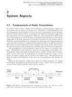
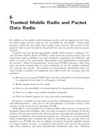
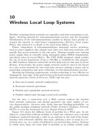
Figure 5.22 Frame structures: (a) W-CDMA and (b) EDGE.
rithm (VA), but instead can obtain path diversity gain by exploiting the delayed path infor-
mation. MLSE thus can have higher efficiency than DFE under the multipath-rich environ-
ment. However, the longer the span of the multipath, the more complicated the hardware
implementation of the VA with the exponential behaviour in complexity as a function of the
span of the ISI. Adaptive antennas on the other hand can suppress the relatively longer-
delayed paths without the hardware overhead, though adaptive antennas cannot obtain path
diversity gain in the same way as the DFE. The joint signal processing of the adaptive
antennas and the equalisers can thus mutually compensate their drawbacks and provide
higher transmission quality and capacity.
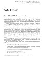
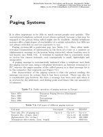
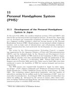
Figure 5.23 shows a block diagram of the space-time equaliser [35,142–144]. The scheme
proposed in [36,37] consists of a couple of adaptive antenna array processors and the branch-
metric combining maximum-likelihood sequence estimator (MLSE). Here the first arrival
and one-symbol-delayed path components are treated as desirable. Other longer delayed path
components are suppressed as undesirable. Each array-processor combines four space-diver-
sity branches to maximise the signal-to-interference-plus-noise ratio (SINR) of the first
arrival and the one-symbol-delayed path components. One array processor combines
space-diversity branches to pass the one-symbol-delayed path component into the array
output with constrained first arrival path component while suppressing other longer delayed
path components.
Likewise, the other array combines space-diversity branches to pass the first arrival path
component into the array output with constrained one-symbol-delayed path component while
suppressing the other longer delayed path components. Consequently, each array processor
extracts both first arrival and one-symbol-delayed path components, whose SINRs in both
diversity branches are improved. Mean-square-error between the array outputs and the repli-
cas are weighted with branch-metric-combining coefficients then combined and input to
MLSE. The adjustable weights in antenna array and one-symbol-delayed tap-coefficients
in the array-output-replica generator are estimated in adaptive weight controller using
constrained-MMSE-criterion-based algorithm. The branch-metric-combining coefficients
Broadband Wireless Mobile: 3G and Beyond292
Figure 5.23 Space-Time equaliser.
can be estimated based on the quality of each diversity branch. By using the pair of array
processors and the branch-metric-combining method for MLSE, a sufficient path diversity
effect can be obtained when the phase differences between first arrival paths to antennas are
significantly different from those on the one-symbol-delayed paths to antennas.
5.3.4 Implementation of the Space-time Equaliser
The recent boom of hardware implementations of adaptive antennas and space-time equali-
sers may be caused by recent advances of reconfigurable hardware such as central processor
units (CPUs), digital-signal-processors (DSPs), field-programmable gate arrays (FPGAs).
Adaptive antennas using digital array processing is thus also called software antennas,
because the digital array processing can be implemented on those programmable devises
by software such as binary pattern. We had developed an experimental system using CPUs,
DSPs and FPGAs, and then evaluated the performances of the adaptive antenna and the
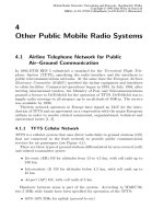
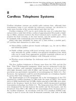
space-time equaliser [35,142,143]. Figure 5.24 shows a photograph of the experimental
system and Table 5.2 describes the main specifications of the system.
A lot of time and effort are still required for the development of the experimental systems
for adaptive antennas and space-time equalisers, though the recent advance in the digital
signal processors. We therefore developed a real-time operating system (RTOS) embedded
fully programmable system for easy implementations of various space and time processing
and also to carry them out simultaneously for comparison in real time.
Figures 5.25 and 2.56 show the experimental results of the adaptive antenna and the space-
time equaliser. Figure 5.25 illustrates bit error rate (BER) performances under frequency-
Initiatives in 4Gmobile Design 293
Figure 5.24 Photograph of the experimental system.
Broadband Wireless Mobile: 3G and Beyond294
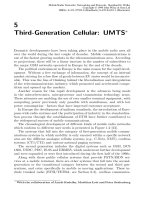
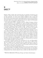
Figure 5.25 Experimental result of the adaptive antenna (AA) and space-time equaliser (AA 1 BMC-
MLSE) under frequency-selective fading channels.
Figure 5.26 Delay time difference characteristics (3-path model).
selective fading channels, in which the number of arrival paths ranges from one to five and the
path delays are fixed multiples of the symbol period (0, 1T
s
,2T
s
,3T
s
,4T
s
). The average power
is equal along all paths of each antenna. The received signal power represents the total power
arriving along all paths, per antenna. Therefore, the average desired power on each path is 1/L
(L: the number of arrival paths) of the total signal power received at each antenna. For the
one-path model, that is, a flat fading channel, the measured BERs of both schemes are almost
equal to a theoretical BER of the four-antenna maximal-ratio-combining (MRC). For the two-
path model, the space-time equaliser has an improved BER because both space-and path
diversity effects are obtained from signals on first and one-symbol-delayed paths. The BER of
the adaptive antenna instead fell as one of its degrees of freedom is consumed in suppressing
the signal on the one-symbol-delayed path. For the three-, four-, and five-path models, the
pace-time equaliser has a significantly lower BER than that of the adaptive antenna. The
space and path diversity effects are especially true for the five-path model because all the
degrees of freedom of the adaptive antenna are used up.
Figure 5.26 shows the delay time difference characteristics in the three-path model, where
the delay time for the second path is set to one symbol and the delay time for the third path is
varied from zero to 6Ts. The BER of the adaptive antenna increases as the difference in delay
times increases. When the space-time equaliser is used, however, the BER keeps low in the
range from zero to one-symbol delay because of the space and path diversity effects from
signals on both first arrival and one-symbol-delayed paths. A one-symbol-delayed path does
not always exist in real channels. However, the one-symbol-delayed path may be able to be
produced by a delay-diversity technique [151].
5.3.5 CDMA Adaptive Array Antennas
Application of adaptive array antennas is now under consideration for CDMA systems [2,5,
12,48,49,72,88–90,99,139] Using adaptive antennas at the base station, we can reduce co-
channel interference, and increase the capacity of CDMA systems. Furthermore, terminals in
Initiatives in 4Gmobile Design 295
Table 5.2 Specifications of the experimental system
Radio channel
Carrier frequency RF/IF 3.35 GHz/245 MHz
Modulation method QPSK
Transmission rate 4.096 Mb/s
Pulse shaping Root Nyquist filter (a ¼ 0.5)
Array signal processing
Number of antennas 4
CPU PowerPC 66 MHz £ 5 (Max.6)
DSP SHARC ADSP2106 (129 MFLOPS) £ 8 (Max. 40)
Real-time operating system VxWorks 3.5.1
Viterbi equaliser (VA)
FPGA 250,000 gates
Number of VA states 4 states
VA path memory length 10 symbols
different angular positions can be served on the same channel with little interference if they
have sufficient angular separation.
Many investigations have been performed on antenna arrays of CDMA systems, including
capacity evaluation, call admission control, and signal processing techniques. Most recent
investigations have focused on space-time processing executed by means of antenna arrays
and a RAKE receiver. In the literature [90], the spatial matched filter is performed before the
despreading process and the filter outputs are despread and coherently combined by a RAKE
combiner. In [99], joint space-time auxiliary-vector filtering is employed in the presence of
multiple-access interference. In literatures [2,5,12,139], whole space-time processing is
performed after the despreading process. The signals in different antennas are despread
using the sequence of the desired terminal where the despread signal is composed of multiple
delay paths. The spatial signal processing is performed for each delay path and the outputs of
the spatial processors are combined by the RAKE combiner. In the spatial processors, the
optimum weight vectors are given by the Wiener-Hopf solution. In [2,139], the optimal
weight vectors are obtained by the normalised least mean square (LMS) algorithm with
pilot symbol-assisted decision-directed coherent adaptive array diversity (PSA-CAAD).
Recently, NTT DoCoMo, Japan, has carried out field experiments and laboratory experiments
of PSA-CAAD with 1.990.5-MHz carrier frequency, 32-kbps information bit rate, 4.096-
Mcps chip rate, and Rayleigh fading environments.
A recent example of technology in other literatures includes multi-user adaptive arrays
with a common correlation matrix (CCM) [49], in which one common correlation matrix is
used to calculate the optimal weight vectors for multiple users. Multi-user adaptive arrays
with CCM can significantly decrease the computational complexity of a base station serving a
number of active terminals.
Another topic of CDMA systems with adaptive antennas is call admission control (CAC).
With CAC, a new call is admitted if there is an available channel; otherwise the call is
blocked. Since the beam pattern of an adaptive array differs terminal by terminal, a new
terminal may suffer from co-channel interference even if another new terminal with a differ-
ent direction does not. Therefore, the direction of the terminal must be considered in CAC. In
[48], the CAC procedure is carried out by estimating new terminal’s signal-to-interference-
plus-noise ratio (SINR) at the output of adaptive array. The admission of new terminal is
determined based on the estimated SINR.
CDMA systems with base-station adaptive arrays are expected to achieve a capacity about
20–30% greater than that of systems with antenna diversity. More precise capacity evaluation
will be required in future research.
5.3.6 SDMA (Spatial Division Multiple Access)
The basic concept of spatial division multiple access (SDMA) [19,26,27,29–33,47,103,116,
147,158] is channel reuse within a cell. With the use of adaptive arrays at the base station,
terminals in different angular positions can share the same time slot reducing the power of other
terminals’ signals. Therefore, the SDMA system is an attractive scheme to increase the capacity
of mobile communication systems. So far, the RACE TSUNAMI [147] project had field trial
demonstration of both receive and transmit digital beamforming supporting SDMA systems. In
addition, many literatures described beamforming methods, assignment algorithms, and power
control in SDMA systems. Let us address some topics of these investigations.
Broadband Wireless Mobile: 3G and Beyond296
Figure 5.27 shows an example of a base station structure with L-branch adaptive antennas
for an SDMA/TDMA system which N communication time slots. Spatially separated K
n
(, L) terminals within a cell share the same time slot n (n ¼ 1,2, ,N) as shown in Figure
5.28. The base station has a channel situation list (Figure 5.29), which stores the covariance
matrix (R
n
), the number of active terminals (K
n
), and the received signal vector of each active
terminal (U
nk
) for each time slot n. The covariance matrix R
n
can be obtained by calculating
the autocorrelation coefficients of total received signals. The matrix R
n
includes the inter-
ference from the outer cell as well as the active terminal’s signal. The parameters in the
channel situation list are updated at a specific time intervals.
In uplink, we can use the optimal weight vector for each user, i.e., Wiener-Hopf solution,
w
nk
¼ R
n
21
U
nk
. In the weight vector calculation process, the channel situation list is referred to
get the information of R
n
21
and U
nk
. In contrast, the downlink optimal weight vector is difficult
to solve because the problem includes a nonlinear constrained optimisation problem. Farsakh
[29] and Zetterberg [158] demonstrated feasible downlink beamforming methods to reduce
interference for higher frequency reuse.
When the base station receives a new call request signal, it searches for an available time
slot to assign. If there is no available time slot, the new terminal is blocked. Careful time slot
assignment can minimise the blocking probability and allow the SDMA system greater
capacity. From such a point of view, a number of algorithms have been proposed for channel
or time slot assignment in an SDMA system. Farsakh [28] described assignment algorithms
based on spatial correlation coefficients. Piolini [103] studied an assignment scheme with cost
coefficients. Shad [116] and Chen [19] provided assignment algorithms based on SINR. In
these investigations, algorithms based on SINR have advantages in managing new terminal’s
signal quality easily because SINR is closely related to signal quality or bit error rate (BER).
Initiatives in 4Gmobile Design 297
Figure 5.27 SDMA/TDMA system with adaptive antennas.
Recently, a time slot assignment algorithm based on estimated SINR has also been
proposed [47]. This algorithm estimates output SINRs of adaptive arrays for new terminal
and for active terminals on the assumption that the new terminal is assigned to a specific time
slot. The estimated SINR of a new terminal for time slot n is represented by:
g
n0
¼ U
H
0
R
21
n
U
0
Broadband Wireless Mobile: 3G and Beyond298
Figure 5.28 Base station structure.
Figure 5.29 Data structure of channel situation list.
Here, U
0
represents a modified signal vector of a new call request signal and H denotes
transpose conjugate. The estimated SINR of active terminal k in time slot n is given by:
g
nk
¼ U
H
0
ðR
n
1 U
0
U
H
0
-U
nk
U
H
nk
Þ
21
U
0
By using estimated SINRs, the proposed algorithm attempts a new call request signal, it
calculates the signal vector of the new terminal and estimates SINRs
g
n0
to search for an
available time slot considering not only the signal quality of the new terminal, but also the
signal quality of active terminals. Figure 5.30 shows a flowchart of highest SINR algorithm.
The time slots are sorted in order of magnitude of the estimated SINRs of the new terminal.
The base station begins to examine whether the time slot with the largest estimated SINR
of the new terminal is available. If all the estimated SINRs of active terminals are above the
required SINR
g
req
, the new terminal is assigned to the time slot. Otherwise, the assignment
process continues to the next time slot according to the time slot ordering until an available
time slot is found. If no time slot is available, the new terminal is blocked.
In this algorithm, the active terminals are always guaranteed to have a suitable SINR after
the time slot assignment process. Therefore, the required signal quality is always maintained
not only for the new terminal, but also for the active terminals. Furthermore, performance
Initiatives in 4Gmobile Design 299
Figure 5.30 Flow chart of highest SINR slot assignment algorithm.
evaluation shows that these time slot assignment algorithms have significantly better perfor-
mance than sectored systems.
Thus, both uplink time slot assignment and downlink slot allocation are important. More
consideration will need to be given to SDMA, including multimedia data transmission, in
future research.
5.3.7 Summary
This section briefly described basic concepts of adaptive antennas, and also introduced a
space-time equaliser. Furthermore, we present the recent investigations of CDMA adaptive
array antennas and SDMA systems. Adaptive antennas can be one of the key technologies in
3G wireless and beyond, and be put into practical use in several years time.
5.4 Multiple Access Schemes
Studies on the concept of the 4G system (beyond IMT-2000), which will be the next genera-
tion of mobile communication, are advanced now and the key technology has been examined.
Because more users will need transmission with a high bit rate and large capacity in such
mobile communication systems in the future, the selection of a multiple access scheme is
important as well as modulation and demodulation. Moreover, the maximum transmission bit
rate will be 20–100 Mbit/s and the transmission bit rate in the reverse link will be higher than
in the forward link. In addition, the importance of transmitting IP packets has been shown by
the development of recent Internet technology. The system construction must be compatible
with these technologies.
The application of a powerful error correcting code and a multi-level modulation technol-
ogy which increases the amount of information transmitted per symbol, is being studied to
reduce multipath fading degradation, which becomes a problem in high bit rate transmission
in mobile communication. To increase the transmission capacity, it is necessary to use
parallel transmission, which allows simultaneous access by several users, and high efficiency
modulation.
In this section, we describe a recent study on transmission technology that focuses on
multiple access. Because it efficiently accommodates a lot of users, the multiple access
method is important. Code division multiple access (CDMA) is used in IMT-2000. For
time division multiple access (TDMA), a lot of research on technology to counter fading
has been studied. It also has the advantage of making the system configuration comparatively
easily. Orthogonal frequency division multiplexing (OFDM) is used for digital broadcasting
and is being researched actively. TDMA and its combination with packet transmission and
multi-carrier CDMA are being examined, though it is not possible to achieve multiple access
with the OFDM unit. It is being paid attention because the modulation method such a multi-
carrier technique offers excellent bit rate and frequency availability.
The transmission capacities of the forward and reverse links are expected to become asym-
metrical because transmission in the reverse link is increasing. Time division duplex (TDD),
which changes the occupation time, and frequency division duplex (FDD), which changes the
frequency band, are typical methods for dealing with this. They give the system different
timings for the start times for the forward and reverse links, and there are problems such as
greater influence of interference from other cells, though TDD is more flexible than FDD.
Broadband Wireless Mobile: 3G and Beyond300
Moreover, the application of an adaptive modulation (multi-level modulation) scheme is
important to improve the transmission efficiency. These schemes are used to enhance the 3G
system. Recently, the use of the space domain has been also studied, such as space division
multiple access (SDMA).
5.4.1 Comparison and Improvement Technology of Multiple Access Schemes
5.4.1.1 CDMA
CDMA offers a large transmission capacity and easy frequency arrangement as a multiple
access method for 3G systems, and a lot of research has been performed on it. The aim is to
improve performance by combining the delay path by the Rake receiver. Since more users are
accommodated, an interference canceller is important.
Wide-band transmission is necessary to transmit tens of Mbit/s in systems beyond IMT-
2000. In this case, the frequency resolution goes up, and the number of observed delay waves
increases. Therefore, the complexity in the Rake receiver increases. To counter this, a method
of limiting the number of delay waves for the Rake combiner has been examined. Moreover,
it is necessary to improve the performance of chip synchronisation and code synchronisation.
Technologies for improving transmission capacity include multi-level modulation, wide-
band transmission and an interference canceller [149], and high efficiency transmission. M-
ary transmission to which information is put to the combination of spreading codes, parallel
combination spread spectrum and the delayed multiplexing transmission [153] to which data
are multiplexed by time delay are proposed as high efficiency transmission. It is necessary to
examine applications considering the transmission quality and capacity. In 3G systems, data
transmission performance can be improved by using turbo code. System designs based on low
C/N operation for a wider-band CDMA system have been studied [57]
5.4.1.2 TDMA
Various technologies have been examined to reduced inter-symbol interference (ISI)
caused by multipath fading, which is becoming a problem, and a lot of research has been
done on high-bit-rate transmission [148]. The method of using multi-level modulation has
been examined for high-bit-rate transmission. However, the TDMA system has problems
such as complex frequency allocation. Various countermeasures, such as dynamic channel
allocation, have been researched to handle this. Moreover, co-channel interference is also
important in effective use of frequency.
Adaptive equalisers, such as the decision feedback equaliser (DFE), and maximum like-
lihood sequence estimation (MLSE) are being researched as the main ways to reduce the
influence of ISI. The adaptive equalisers have been researched. However, when long delay
waves exist, there is a problem of growing the complexity. On the other hand, the adaptive
array antenna is also effective for removing delayed waves, and it does not depend on the
delay time of more than one symbol of the delay wave. However, a path diversity effect
cannot be obtained, and there are problems such as being unable to remove the influence of
the delay wave from the same direction. Therefore, to make best use of both in the future,
space-time signal processing technology has also been studied.
Initiatives in 4Gmobile Design 301
5.4.1.3 OFDM
Orthogonal frequency division multiplex (OFDM) maintains the orthogonality of each carrier
and transmits by frequency division multiplexing (FDM) using two or more carriers. All
carriers are synchronised and the frequency use efficiency is high because it is by orthogo-
nalising each sub-carrier arrangement. However, when the transmission line has nonlinear
characteristics, they are deteriorated by mutual modulation. Moreover, when the peak-to-
average power ratio (PAPR) increases when there are many carriers, and a nonlinear amplifier
is used, a warp is easily caused. There are problems such as the device becoming complex
when the number of carriers increases.
The symbol duration depends for a long time, and it can reduce the ISI generated by the
delayed waves. Therefore, it is an effective measure for combating frequency selection fading
in mobile communications.
Coded OFDM (COFDM), which uses error correcting code, can achieve a frequency
interleaving effect. The effect of the error correcting code can be effectively demonstrated
by using it together with time domain interleaving, and the effect of time and frequency
diversity can be obtained.
In OFDM, the influence of ISI is removed by inserting a guard interval, which also enables
the symbol timing and frequency offset to be estimated. A method of processing these with
high accuracy by using a pilot symbol has been examined. An adaptive equaliser can reduce
ISI when there are delayed waves that exceed the guard interval. As a result, the orthogonality
between sub-carriers can be maintained.
For a multimedia high-bit-rate transmission system, methods that use both adaptive-level-
controlled modulation and packet transmission have been studied. This system can transmit at
tens of Mb/s and has changed modulation level and coding rate of the error correction as the
channel condition in a pedestrian environment [93].
On the other hand, band division multiple access (BDMA) [66] multiplexed by a similar
control to TDMA has been proposed to divide the band. This method was proposed as a
candidate for the IMT-2000 system. It can achieving path diversity by using frequency
hopping with error correction and can reduce interference from other cells.
5.4.2 Multi-carrier CDMA
Multi-carrier CDMA is a transmission method using two or more carriers. It has been actively
researched to achieve excellent frequency use efficiency and counter multipath fading.
There are two main types:
† the band division type and
† the OFDM type, which uses the orthogonalisation frequency.
The band division type is already in practical use in the cdma2000 system. We examined
the OFDM type. The combined OFDM/CDMA method, which features the good points of
both OFDM and CDMA, is robust in a very bad multipath environment in mobile commu-
nications, and achieves both a high bit rate and large capacity.
One problem is that PAPR grows more than in the usual OFDM under multiplex condi-
tions. PAPR definitely grows compared with single-carrier CDMA. Moreover, the advantage
of direct spreading is not obtained with OFDM/CDMA. A compensator is necessary to keep
Broadband Wireless Mobile: 3G and Beyond302
the orthogonalisation between carriers. Moreover, the deterioration of performance is often
produced in a high-speed fading environment, so the symbol or chip duration is compara-
tively long.
Multi-carrier CDMA is classified into three kinds as follows, depending on the method that
is combined with it [50].
5.4.2.1 Principles and feature of three methods of multi-carrier CDMA
The principle and spectrum of each method is shown in Figure 5.31 and Table 5.3.
5MC-DS/CDMA
In this method, the sub-carrier, which is spread directly as shown in Figure 5.31(a), is
arranged orthogonally. This is multiplied by the code in the frequency domain, and spread
in the time domain. The influence of multiple access interference (MAI) by the mutual
correlation of the spread factor is large, and the influence of the ability to identify the delayed
waves by the auto correlation characteristics of the spread code is also large. Therefore, a
system with comparatively few sub-carriers is possible. Moreover, the spread factor for each
sub-carrier is smaller than in single-carrier CDMA and the BER performance is improved by
the RAKE receiver.
The characteristics can be improved by using a RAKE receiver of the each sub-carrier
signal. However, it is difficult to use all the signal energy spread on the time axis in the
receiver. To increase the transmission capacity, the parallel combination of MC-DS/CDMA
is being studied [34].
MC-CDMA
The MC-CDMA system spreads each chip of the spread codes on the frequency axis in the
each sub-carrier as shown in Figure 5.31(b). The spread code is an orthogonal code of the
Hadamard Walsh code [21]. That is, CDMA will be done in the frequency domain. To
achieve a path diversity effect, it will be necessary to increase the number of sub-carriers.
Moreover, the performance can be improved by using a equaliser for each sub-carrier.
In the MC-CDMA system, making to the implementation is comparatively easy. Although,
the orthogonalisation degrades in CDMA under the delay time more than single-chip dura-
tion, the deterioration of performance has little in MC-CDMA because the data spreads to the
frequency area. Moreover, all the signal energy can be used in the receiver.
Multi-tone CDMA (MT-CDMA)
In this method, the OFDM signal is spread directly as shown in Figure 5.31(c). Therefore,
after despreading, the sub-carriers are not orthogonal. The number of sub-carriers is small.
The spread factor for each sub-carrier is larger than in MC-DS/CDMA. Moreover, the BER
performance is improved by the RAKE receiver.
An orthogonal frequency division multiplex is done in each symbol. A high spread gain is
obtained. Because the spread code length increases in proportion to the number of sub-
carriers, more spread codes can be accommodated that in single-carrier CDMA.
Initiatives in 4Gmobile Design 303
Broadband Wireless Mobile: 3G and Beyond304
Figure 5.31 Principles of (a) MC-CDMA, (b) MC/DS-CDMA, and (c) MT-CDMA.
5.4.2.2 Performance comparison
To compare the performances of the methods, we carried out computer simulations using the
same bandwidth. We chose narrow-band transmission for convenience and decreased the
number of sub-carriers and compared the performance. Figure 5.32 shows the simulation
results and Table 5.4 shows the simulation conditions. In Figure 5.32, as the number of users
increases, MT-CDMA becomes greatly degraded. The reason for the degradation is the large
influence of mutual correlation of the code when an M-sequence is used for the spread code.
The bit error rate versus the number of users was compared with MC/DS-CDMA and MC-
CDMA in a frequency selective fading environment by a computer simulation. The simula-
tion results in the forward and reverse link and are shown in Figures 5.33(a) and (b), respec-
tively. Table 5.5 shows the simulation conditions. MC-DS/CDMA used Rake receiver with
four fingers by equal gain combining. MC-CDMA is simultaneously transmitted with 16
symbols in frequency domain.
MC-CDMA is rapidly degraded when there are more than two users in the forward link.
The reason for this is that the orthogonalisation collapses due to interference from the other
user’s delay waves, because each user has a different propagation path. Thus, the number of
users that can obtain access simultaneously is limited.
Initiatives in 4Gmobile Design 305
Table 5.3 Features of multi-carrier CDMA
Method MC-CDMA MC-DS/CDMA MT-CDMA
Spread Code spread in
frequency domain
Direct spread and multi-
carrier in time domain
Direct spread of
multi-carrier signal
Rake receiver none good excellent
Frequency diversity effect excellent available none
Figure 5.32 Average BER performance.
Broadband Wireless Mobile: 3G and Beyond306
Table 5.4 Simulation conditions for performance comparison of three methods
Transmission bit rate 256 kbit/s
Bandwidth 16.6 MHz
Modulation QPSK
Number of sub-carriers MC-DS/CDMA: 128; MT-CDMA: 2; MC-CDMA: 128
Spread code M-sequence (code length: 128)
Fading None
Figure 5.33 BER characteristics on (a) forward link, and. (b) reverse link.
We think that MC-CDMA is effective to the transmission capacity improvement by the
reverse link and in the point of implement because the Rake receiver is unnecessary. Ortho-
gonalisation techniques become important in the reverse link [51].
5.4.3 Summary
Multiple access technology for 4G systems was examined. In particular, we compared
various multi-carrier CDMA methods. The CDMA system is effective, considering compat-
ibility and the frequency arrangement with a 3G system. Moreover, the multi-carrier system
transmission is effective as the improvement of the frequency efficiency and the frequency
selective fading measures. In particular, multi-carrier CDMA is effective as a multiple access
method. Moreover, combining it with an SDMA method is also promising.
Multiple access technology is a basic air interface includes the modulation method, and the
method of combining time, frequency and space flexibly and efficiently will be used. More-
over, it is necessary to examine methods of dealing with the carrier frequency and propaga-
tion characteristics. Examination methods for suitable systems will be advanced by
development such as software defined radios.
In the future, it will also be necessary to examine a simple algorithm to improve these
methods inexpensively.
5.5 CDMA Dynamic Cell Configuration
5.5.1 Teletraffic Load in Cellular Radio Systems
Estimating the volume of teletraffic is a key to supplying services with which users are
sufficiently satisfied and investing in appropriate equipment for cellular radio systems.
However, designing a teletraffic profile is exceedingly difficult because the teletraffic volume
differs in different regions and districts, and it also varies, depending on the time, day, or
month. Since installing a system is very costly, developing it requires taking the increase in
teletraffic volume and future services into consideration. However, anticipating the popula-
tion flow, service demands, and new technologies is difficult, even for experts.
Cellular radio systems face some difficulties handling teletraffic, which do not occur in
wired-communication services. In cellular radio systems, frequency resources for commu-
nications are limited and are reused in different places. Consequently, interference occurs
Initiatives in 4Gmobile Design 307
Table 5.5 Simulation parameters for comparison of MC-CDMA and MC-DS/CDMA
Transmission information bit rate 256 kbit/s
Band width MC-DS/CDMA: 65.55 MHz; MC-CDMA: 65.67 MHz
Modulation QPSK
Number of sub-carriers 32
Spread code MC-DS/CDMA: Orthogonal Gold; MC-CDMA: Walsh
Haramard; code length: 128
Fading conditions 6-ray Rayleigh model; Delay spread: 500 ns; Maximum
Doppler frequency: 300 Hz
among communications using the same frequency, which is the greatest difficulty in cellular
radio systems. The service area of a cellular system is covered by cells, which in turn are
controlled by a single base station (BS). Designing an efficient system requires considering
the following factors:
† BS locations and intervals
† individual cell shapes
† teletraffic volume for each BS
† frequency resource allocation to each cell.
Figure 5.34 shows an example of teletraffic loads and their corresponding cell structures.
The loads differ from place to place. An area with a large teletraffic load is covered by smaller
cells to increase the frequency re-use efficiency. However, cells are not always structured
ideally because of the influence of large buildings and the lack of sites where a BS can be
located. There are locally congested areas within a cell, and interference occurs between
different-sized cells. Unevenness in interference is closely related to the traffic situations. The
most striking feature of cellular radio systems is to allow using mobile terminals (or mobile
stations (MSs)), which move freely within a cell or between cells in a service area. Due to
these movements, teletraffic and interference characteristics vary and affect the system
locally.
Third-generation (3G) mobile systems provide voice and data services with some times
higher transmission rates than voice-transmission rates. The 4G systems should provide
multimedia communications that include services with even higher transmission rates.
Hence, the teletraffic profiles for a local area will change significantly over time. Traffic
loads on the up and the downlinks are likely to differ greatly, and the downlink load will be
huge because it provides various download services. Some methods that share the resources,
frequency, time, power, or space, flexibly between both links or use a different system for
each link are being studied now. The quality of service (QoS) required by each user also
differs, and the system will demand the efficient accommodation of different services or select
an access method that is suitable for each service.
5.5.2 Teletraffic Management and Access Methods
To handle geographically uneven teletraffic distribution, in an area with a large traffic load,
Broadband Wireless Mobile: 3G and Beyond308
Figure 5.34 Uneven teletraffic and cell areas.
the distance between BSs is shortened and the cell area is reduced; this method is commonly
applied in cellular radio systems. To efficiently accommodate teletraffic that is uneven in
terms of place and time, different approaches are taken depending on the access method. To
enhance a system efficiency for access methods that divide frequency, such as FDMA or
TDMA, particularly requires allocating and using frequency channels effectively to avoid co-
channel interference. In CDMA, where multiple users simultaneously share the same
frequency band, an increase in interference becomes problematic, therefore balancing the
volume of interference within a cell or between cells is essential. In access methods using
multi-carrier communications, carrier assignment to each cell/user and appropriate power
allocation to each carrier may be studied in the future.
5.5.3 Channel Assignment
The effect of uneven traffic in cellular radio systems can be reduced using some techniques. In
frequency-division cellular systems, frequency channels are allocated to each cell and used
repeatedly in different places. The efficiency of channel allocation determines the system
capacity. When a system is installed, teletraffic distribution and interference between co-
channels are considered in assigning frequency channels. Moreover, the channel assignment
can be dynamically changed according to variations in traffic load by applying channel-
assignment algorithms. However, only simple algorithms have been adopted in some
systems. Anticipating multimedia communications, channel-allocation and time-slot-alloca-
tion methods, such as to accommodate high-rate transmission and to share common
frequency resources flexibly between the up and downlink, are being developed to accom-
modate various services.
5.5.4 Control Methods in CDMA Systems
In CDMA cellular systems, each signal is spread over a spectrum and uses a common
frequency band (or several common frequency bands). Using the same frequency band
means that the frequency-reuse factor becomes unity, so there is no need for frequency
planning (such as frequency-channel allocation). On the other hand, CDMA systems cannot
handle uneven teletraffic distribution or a large difference in traffic load over time, because
these systems do not adapt allocating frequency channels to the traffic load. The CDMA
system work best when the traffic patterns are uniform because it shares a frequency resource
equally among channels or between cells [40,68]. The capacity of the CDMA system depends
on the amount of interference from all users. The difference in received power depends on the
MS locations. This ‘near-far problem’ causes unnecessary interference and reduces system
capacity.
To solve this problem, CDMA systems require accurate transmission power control
(TPC). Because the power level is proportional to the transmission rate, variation in teletraffic
can be expressed as variation in interference (however, this relation is not in direct propor-
tion). Therefore, balancing the interference is the key to efficiently accommodating teletraffic
in CDMA systems. An SIR-based (or frame-error rate-based) power control [110] can adap-
tively control the transmission power to meet the required quality level. However, an extreme
increase in transmission power degrades the quality in other cells, so this power control
method is not effective for large teletraffic variations.
Initiatives in 4Gmobile Design 309
Several methods have been studied for handling large teletraffic variations and unevenness
in CDMA systems. Access control methods restrict new call requests when the system is fully
occupied. To avoid strong interference, the system is divided into time, frequency, or space
domains. In a time-division system, time slots are allocated to users by considering traffic and
interference variations. Space-division methods using adaptive antennas are also being
studied. We describe one such method, in which cell areas are adaptively configured to
control the amount of interference and traffic between cells.
5.5.5 Principle of Dynamic Cell Configuration (DCC)
An MS selects a BS to connect to by measuring the received power of the pilot signals from the
adjacent BSs. Figure 5.35 shows the relation between the pilot signals and the cell boundary.
The transmission power of the pilot signal is indicated by P
P
. The point where the received
powers of the two pilot signals from adjacent BSs intersect is the cell boundary. If the propaga-
tion conditions between BS1 and BS
2
are the same, and if P
P1
¼ P
P2
, the distances from both
BSs to the cell boundary are equal (R
1
¼ R
2
), and both cell areas are equal.
In DCC, the pilot-signal transmission power and the uplink target power level at each BS
are adjusted autonomously according to the communications quality. In this case, only
uplink quality is considered. The cell area can be configured flexibly by controlling the
pilot-signal power, and anti-interference characteristics can be improved by adjusting the
target power level.
Broadband Wireless Mobile: 3G and Beyond310
Figure 5.35 (a) Relation between power of pilot signals and cell boundary: cell boundary determined
by power of received pilot signals. (b) Relation between power of pilot signals and cell boundary:
control of cell boundary by manipulating power of pilot signals.