Tài liệu Lọc Kalman - lý thuyết và thực hành bằng cách sử dụng MATLAB (P6) docx
Bạn đang xem bản rút gọn của tài liệu. Xem và tải ngay bản đầy đủ của tài liệu tại đây (597.2 KB, 68 trang )
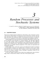
6
Implementation Methods
There is a great difference between theory and practice.
Giacomo Antonelli (1806±1876)
1
6.1 CHAPTER FOCUS
Up to this point, we have discussed what Kalman ®lters are and how they are
supposed to behave. Their theoretical performance has been shown to be character-
ized by the covariance matrix of estimation uncertainty, which is computed as the
solution of a matrix Riccati differential equation or difference equation.
However, soon after the Kalman ®lter was ®rst implemented on computers, it was
discovered that the observed mean-squared estimation errors were often much larger
than the values predicted by the covariance matrix, even with simulated data. The
variances of the ®lter estimation errors were observed to diverge from their
theoretical values, and the solutions obtained for the Riccati equation were observed
to have negative variances, an embarrassing example of a theoretical impossibility.
The problem was eventually determined to be caused by computer roundoff, and
alternative implementation methods were developed for dealing with it.
This chapter is primarily concerned with
1. how computer roundoff can degrade Kalman ®lter performance,
2. alternative implementation methods that are more robust against roundoff
errors, and
3. the relative computational costs of these alternative implementations.
1
In a letter to the Austrian Ambassador, as quoted by Lytton Strachey in Eminent Victorians [101].
Cardinal Antonelli was addressing the issue of papal infallibility, but the same might be said about the
infallibility of numerical processing systems.
202
Kalman Filtering: Theory and Practice Using MATLAB, Second Edition,
Mohinder S. Grewal, Angus P. Andrews
Copyright # 2001 John Wiley & Sons, Inc.
ISBNs: 0-471-39254-5 (Hardback); 0-471-26638-8 (Electronic)
6.1.1 Main Points to Be Covered
The main points to be covered in this chapter are the following:
1. Computer roundoff errors can and do seriously degrade the performance of
Kalman ®lters.
2. Solution of the matrix Riccati equation is a major cause of numerical
dif®culties in the conventional Kalman ®lter implementation, from the
standpoint of computational load as well as from the standpoint of computa-
tional errors.
3. Unchecked error propagation in the solution of the Riccati equation is a major
cause of degradation in ®lter performance.
4. Asymmetry of the covariance matrix of state estimation uncertainty is a
symptom of numerical degradation and a cause of numerical instability, and
measures to symmetrize the result can be bene®cial.
5. Numerical solution of the Riccati equation tends to be more robust against
roundoff errors if Cholesky factors or modi®ed Cholesky factors of the
covariance matrix are used as the dependent variables.
6. Numerical methods for solving the Riccati equation in terms of Cholesky
factors are called factorization methods, and the resulting Kalman ®lter
implementations are collectively called square-root ®ltering.
7. Information ®ltering is an alternative state vector implementation that
improves numerical stability properties. It is especially useful for problems
with very large initial estimation uncertainty.
6.1.2 Topics Not Covered
1. Parametric Sensitivity Analysis. The focus here is on numerically stable
implementation methods for the Kalman ®lter. Numerical analysis of all errors
that in¯uence the performance of the Kalman ®lter would include the effects of
errors in the assumed values of all model parameters, such as Q, R, H, and F.
These errors also include truncation effects due to ®nite precision. The sensitiv-
ities of performance to these types of modeling errors can be modeled mathe-
matically, but this is not done here.
2. Smoothing Implementations. There have been signi®cant improvements
in smoother implementation methods beyond those presented in Chapter 4. The
interested reader is referred to the surveys by Meditch [201] (methods up to 1973)
and McReynolds [199] (up to 1990) and to earlier results by Bierman [140] and
by Watanabe and Tzafestas [234].
6.1 CHAPTER FOCUS 203
3. Parallel Computer Architectures for Kalman Filtering. The operation
of the Kalman ®lter can be speeded up, if necessary, by performing some
operations in parallel. The algorithm listings in this chapter indicate those
loops that can be performed in parallel, but no serious attempt is made to
de®ne specialized algorithms to exploit concurrent processing capabilities. An
overview of theoretical approaches to this problem is presented by Jover and
Kailath [175].
6.2 COMPUTER ROUNDOFF
Roundoff errors are a side effect of computer arithmetic using ®xed- or ¯oating-
point data words with a ®xed number of bits. Computer roundoff is a fact of life for
most computing environments.
EXAMPLE 6.1: Roundoff Errors In binary representation, the rational numbers
are transformed into sums of powers of 2, as follows:
1 2
0
3 2
0
2
1
1
3
1
4
1
16
1
64
1
256
ÁÁÁ
0
b
0101010101010101010101010 ;
where the subscript ``b'' represents the ``binary point'' in binary representation (so as
not to be confused with the ``decimal point'' in decimal representation). When 1 is
divided by 3 in an IEEE=ANSI standard [107] single-precision ¯oating-point
arithmetic, the 1 and the 3 can be represented precisely, but their ratio cannot.
The binary representation is limited to 24 bits of mantissa.
2
The above result is then
rounded to the 24-bit approximation (starting with the leading ``1''):
1
3
% 0
b
0101010101010101010101011
11184811
33554432
1
3
À
1
100663296
;
giving an approximation error magnitude of about 10
À8
and a relative approximation
error of about 3 Â10
À8
. The difference between the true value of the result and the
value approximated by the processor is called roundoff error.
2
The mantissa is the part of the binary representation starting with the leading nonzero bit. Because the
leading signi®cant bit is always a ``1,'' it can be omitted and replaced by the sign bit. Even including the
sign bit, there are effectively 24 bits available for representing the magnitude of the mantissa.
204 IMPLEMENTATION METHODS
6.2.1 Unit Roundoff Error
Computer roundoff for ¯oating-point arithmetic is often characterized by a single
parameter e
roundoff
, called the unit roundoff error, and de®ned in different sources as
the largest number such that either
1 e
roundoff
1 in machine precision 6:1
or
1 e
roundoff
=2 1 in machine precision. 6:2
The name ``eps'' in MATLAB is the parameter satisfying the second of these
equations. Its value may be found by typing ``epsh
RETURNi'' (i.e., typing ``eps''
without a following semicolon, followed by hitting the RETURN or ENTER key) in
the MATLAB command window. Entering ``-log2(eps)''should return the number of
bits in the mantissa of the standard data word.
6.2.2 Effects of Roundoff on Kalman Filter Performance
Many of the roundoff problems discovered in the earlier years of Kalman ®lter
implementation occurred on computers with much shorter wordlengths than those
available in most MATLAB implementations and less accurate implementations of
bit-level arithmetic than the current ANSI standards.
However, the next example (from [156]) demonstrates that roundoff can still be a
problem in Kalman ®lter implementations in MATLAB environments and how a
problem that is well-conditioned, as posed, can be made ill-conditioned by the ®lter
implementation.
EXAMPLE 6.2 Let I
n
denote the n  n identity matrix. Consider the ®ltering
problem with measurement sensitivity matrix
H
11 1
111 d
!
and covariance matrices
P
0
I
3
and R d
2
I
2
where d
2
< e
roundoff
but d > e
roundoff
. In this case, although H clearly has rank 2in
machine precision, the product HP
0
H
T
with roundoff will equal
33 d
3 d 3 2d
!
;
6.2 COMPUTER ROUNDOFF 205
which is singular. The result is unchanged when R is added to HP
0
H
T
. In this case,
then, the ®lter observational update fails because the matrix HP
0
H
T
R is not
invertible.
Sneak Preview of Alternative Implementations. Figure 6.1 illustrates how
the standard Kalman ®lter and some of the alternative implementation methods
perform on the variably ill-conditioned problem of Example 6.2 (implemented as
MATLAB m-®le shootout.m on the accompanying diskette) as the conditioning
parameter d 3 0. All solution methods were implemented in the same precision (64-
bit ¯oating point) in MATLAB. The labels on the curves in this plot correspond to
the names of the corresponding m-®le implementations on the accompanying
diskette. These are also the names of the authors of the corresponding methods,
the details of which will be presented further on.
For this particular example, the accuracies of the methods labeled ``Carlson'' and
``Bierman'' appear to degrade more gracefully than the others as d 3 e, the machine
precision limit. The Carlson and Bierman solutions still maintain about 9 digits
(% 30 bits) of accuracy at d %
e
p
, when the other methods have essentially no bits
of accuracy in the computed solution.
This one example, by itself, does not prove the general superiority of the Carlson
and Bierman solutions for the observational updates of the Riccati equation. The full
implementation will require a compatible method for performing the temporal
update, as well. (However, the observational update had been the principal source
of dif®culty with the conventional implementation.)
Fig. 6.1 Degradation of Riccati equation observational updates with problem conditioning.
206 IMPLEMENTATION METHODS
6.2.3 Terminology of Numerical Error Analysis
We ®rst need to de®ne some general terms used in characterizing the in¯uence of
roundoff errors on the accuracy of the numerical solution to a given computation
problem.
Robustness and Numerical Stability. These terms are used to describe
qualitative properties of arithmetic problem-solving methods. Robustness refers to
the relative insensitivity of the solution to errors of some sort. Numerical stability
refers to robustness against roundoff errors.
Precision versus Numerical Stability. Relative roundoff errors can be
reduced by using more precision (i.e., more bits in the mantissa of the data
format), but the accuracy of the result is also in¯uenced by the accuracy of the
initial parameters used and the procedural details of the implementation method.
Mathematically equivalent implementation methods can have very different numer-
ical stabilities at the same precision.
Numerical Stability Comparisons. Numerical stability comparisons can be
slippery. Robustness and stability of solution methods are matters of degree, but
implementation methods cannot always be totally ordered according to these
attributes. Some methods are considered more robust than others, but their relative
robustness can also depend upon intrinsic properties of the problem being solved.
Ill-Conditioned and Well-Conditioned Problems. In the analysis of numer-
ical problem-solving methods, the qualitative term ``conditioning'' is used to
describe the sensitivity of the error in the output (solution) to variations in the
input data (problem). This sensitivity generally depends on the input data and the
solution method.
A problem is called well-conditioned if the solution is not ``badly''sensitive to the
input data and ill-conditioned if the sensitivity is ``bad.'' The de®nition of what is
bad generally depends on the uncertainties of the input data and the numerical
precision being used in the implementation. One might, for example, describe a
matrix A as being ``ill-conditioned with respect to inversion'' if A is ``close'' to being
singular. The de®nition of ``close'' in this example could mean within the
uncertainties in the values of the elements of A or within machine precision.
EXAMPLE 6.3: Condition Number of a Matrix The sensitivity of the solution
x of the linear problem Ax b to uncertainties in the input data (A and b) and
roundoff errors is characterized by the condition number of A, which can be de®ned
as the ratio
condA
max
x
kAxk=kxk
min
x
kAxk=kxk
6:3
6.2 COMPUTER ROUNDOFF 207
if A is nonsingular and as I if A is singular. It also equals the ratio of the largest and
smallest characteristic values of A. Note that the condition number will always be
!1 because max ! min. As a general rule in matrix inversion, condition numbers
close to 1 are a good omen, and increasingly larger values are cause for increasing
concern over the validity of the results.
The relative error in the computed solution
^
x of the equation Ax b is de®ned as
the ratio k
^
x À xk=kxk of the magnitude of the error to the magnitude of x.
As a rule of thumb, the maximum relative error in the computed solution is
bounded above by c
A
e
roundoff
condA, where e
roundoff
is the unit roundoff error in
computer arithmetic (de®ned in Section 6.2.1) and the positive constant c
A
depends
on the dimension of A. The problem of computing x, given A and b, is considered ill-
conditioned if adding 1 to the condition number of A in computer arithmetic has no
effect. That is, the logical expression 1 condAcondA evaluates to true.
Consider an example with the coef®cient matrix
A
1 L 0
01L
001
P
T
R
Q
U
S
;
where
L 2
64
18;446;744;073;709;551;616;
which is such that computing L
2
would cause over¯ow in ANSI standard single-
precision arithmetic.
The condition number of A will then be
condA%3:40282 Â 10
38
:
This is about 31 orders of magnitude beyond where the rule-of-thumb test for ill-
conditioning would fail in this precision (%2 Â 10
7
). One would then consider A
extremely ill-conditioned for inversion (which it is) even though its determinant
equals 1.
Programming note: For the general linear equation problem Ax b, it is not
necessary to invert A explicitly in the process of solving for x, and numerical stability
is generally improved if matrix inversion is avoided. The MATLAB matrix divide
(using x Anb) does this.
6.2.4 Ill-Conditioned Kalman Filtering Problems
For Kalman ®ltering problems, the solution of the associated Riccati equation should
equal the covariance matrix of actual estimation uncertainty, which should be
208 IMPLEMENTATION METHODS
optimal with respect to all quadratic loss functions. The computation of the Kalman
(optimal) gain depends on it. If this does not happen, the problem is considered ill-
conditioned. Factors that contribute to such ill-conditioning include the following:
1. Large uncertainties in the values of the matrix parameters F, Q, H ,orR. Such
modeling errors are not accounted for in the derivation of the Kalman ®lter.
2. Large ranges of the actual values of these matrix parameters, the measure-
ments, or the state variablesÐall of which can result from poor choices of
scaling or dimensional units.
3. Ill-conditioning of the intermediate result R
Ã
HPH
T
R for inversion in the
Kalman gain formula.
4. Ill-conditioned theoretical solutions of the matrix Riccati equationÐwithout
considering numerical solution errors. With numerical errors, the solution may
become inde®nite, which can destabilize the ®lter estimation error.
5. Large matrix dimensions. The number of arithmetic operations grows as the
square or cube of matrix dimensions, and each operation can introduce
roundoff errors.
6. Poor machine precision, which makes the relative roundoff errors larger.
Some of these factors are unavoidable in many applications. Keep in mind that they
do not necessarily make the Kalman ®ltering problem hopeless. However, they are
cause for concernÐand for considering alternative implementation methods.
6.3 EFFECTS OF ROUNDOFF ERRORS ON KALMAN FILTERS
Quantifying the Effects of Roundoff Errors on Kalman Filtering.
Although there was early experimental evidence of divergence due to roundoff
errors, it has been dif®cult to obtain general principles describing how it is related to
characteristics of the implementation. There are some general (but somewhat weak)
principles relating roundoff errors to characteristics of the computer on which the
®lter is implemented and to properties of the ®lter parameters. These include the
results of Verhaegen and Van Dooren [232] on the numerical analysis of various
implementation methods in Kalman ®ltering. These results provide upper bounds on
the propagation of roundoff errors as functions of the norms and singular values of
key matrix variables. They show that some implementations have better bounds than
others. In particular, they show that certain ``symmetrization'' procedures are
provably bene®cial and that the so-called square-root ®lter implementations have
generally better error propagation bounds than the conventional Kalman ®lter
equations.
Let us examine the ways that roundoff errors propagate in the computation of the
Kalman ®lter variables and how they in¯uence the accuracy of results in the Kalman
®lter. Finally, we provide some examples that demonstrate common failure modes.
6.3 EFFECTS OF ROUNDOFF ERRORS ON KALMAN FILTERS 209
6.3.1 Roundoff Error Propagation in Kalman Filters
Heuristic Analysis. We begin with a heuristic look at roundoff error propagation,
from the viewpoint of the data ¯ow in the Kalman ®lter, to show how roundoff errors
in the Riccati equation solution are not controlled by feedback like roundoff errors in
the estimate. Consider the matrix-level data ¯ow diagram of the Kalman ®lter that is
shown in Figure 6.2. This ®gure shows the data ¯ow at the level of vectors and
Fig. 6.2 Kalman ®lter data ¯ow.
210 IMPLEMENTATION METHODS
matrices, with operations of addition (È), multiplication (), and inversion (I Ä).
Matrix transposition need not be considered a data operation in this context, because
it can be implemented by index changes in subsequent operations. This data ¯ow
diagram is fairly representative of the straightforward Kalman ®lter algorithm, the
way it was originally presented by Kalman, and as it might be implemented in
MATLAB by a moderately conscientious programmer. That is, the diagram shows
how partial results (including the Kalman gain,
K) might be saved and reused. Note
that the internal data ¯ow can be separated into two, semi-independent loops within
the dashed boxes. The variable propagated around one loop is the state estimate. The
variable propagated around the other loop is the covariance matrix of estimation
uncertainty. (The diagram also shows some of the loop ``shortcuts'' resulting from
reuse of partial results, but the basic data ¯ows are still loops.)
Feedback in the Estimation Loop. The uppermost of these loops, labeled EST.
LOOP, is essentially a feedback error correction loop with gain (
K) computed in the
other loop (labeled GAIN LOOP). The difference between the expected value H
^
x of
the observation z (based on the current estimate
^
x of the state vector) and the
observed value is used in correcting the estimate
^
x. Errors in
^
x will be corrected by
this loop, so long as the gain is correct. This applies to errors in
^
x introduced by
roundoff as well as those due to noise and a priori estimation errors. Therefore,
roundoff errors in the estimation loop are compensated by the feedback mechanism,
so long as the loop gain is correct. That gain is computed in the other loop.
No Feedback in the Gain Loop. This is the loop in which the Riccati equation is
solved for the covariance matrix of estimation uncertainty (P), and the Kalman gain
is computed as an intermediate result. It is not stabilized by feedback, the way that
the estimation loop is stabilized. There is no external reference for correcting the
``estimate'' of P. Consequently, there is no way of detecting and correcting the
effects of roundoff errors. They propagate and accumulate unchecked. This loop also
includes many more roundoff operations than the estimation loop, as evidenced by
the greater number of matrix multiplies () in the loop. The computations involved
in evaluating the ®lter gains are, therefore, more suspect as sources of roundoff error
propagation in this ``conventional'' implementation of the Kalman ®lter. It has been
shown by Potter [209] that the gain loop, by itself, is not unstable. However, even
bounded errors in the computed value of P may momentarily destabilize the
estimation loop.
EXAMPLE 6.4 An illustration of the effects that negative characteristic values
of the computed covariance matrix P can have on the estimation errors is shown
below:
6.3 EFFECTS OF ROUNDOFF ERRORS ON KALMAN FILTERS 211
Roundoff errors can cause the computed value of P to have a negative characteristic
value. The Riccati equation is stable, and the problem will eventually rectify itself.
However, the effect on the actual estimation error can be a more serious problem.
Because P is a factor in the Kalman gain K, a negative characteristic value of P
can cause the gain in the prediction error feedback loop to have the wrong sign.
However, in this transient condition, the estimation loop is momentarily destabilized.
In this illustration, the estimate
^
x converges toward the true value x until the gain
changes sign. Then the error diverges momentarily. The gain computations may
eventually recover with the correct sign, but the accumulated error due to divergence
is not accounted for in the gain computations. The gain is not as big as it should be,
and convergence is slower than it should be.
6.3.1.1 Numerical Analysis. Because the a priori value of P is the one used in
computing the Kalman gain, it suf®ces to consider just the error propagation of that
value. It is convenient, as well, to consider the roundoff error propagation for xÀ.
A ®rst-order roundoff error propagation model is of the form
dx
k1
À f
1
dx
k
À; dP
k
À Dx
k1
; 6:4
dP
k1
À f
2
dP
k
À DP
k1
À; 6:5
where the d term refers to the accumulated error and the D term refers to the added
roundoff errors on each recursion step. This model ignores higher order terms in the
error variables. The forms of the appropriate error propagation functions are given in
Table 6.1. Error equations for the Kalman gain are also given, although the errors in
K
k
depend only on the errors in x and PÐthey are not propagated independently.
These error propagation function values are from the paper by Verhaegen and Van
212 IMPLEMENTATION METHODS
Dooren [232]. (Many of these results have also appeared in earlier publications.)
These expressions represent the ®rst-order error in the updated a prior variables on
the k 1th temporal epoch in terms of the ®rst-order errors in the kth temporal
epoch and the errors added in the update process.
Roundoff Error Propagation. Table 6.1 compares two ®lter implementation types,
in terms of their ®rst-order error propagation characteristics. One implementation
type is called ``conventional.'' That corresponds to the straightforward implementa-
tion of the equations as they were originally derived in previous chapters, excluding
the ``Joseph-stabilized'' implementation mentioned in Chapter 4. The other type is
called ``square root,'' the type of implementation presented in this chapter. A further
breakdown of these implementation types will be de®ned in later sections.
Propagation of Antisymmetry Errors. Note the two terms in Table 6.1 involving
the antisymmetry error dP
k
À À dP
T
k
À in the covariance matrix P, which tends to
con®rm in theory what had been discovered in practice. Early computers had very
little memory capacity, and programmers had learned to save time and memory by
computing only the unique parts of symmetric matrix expressions such as FPF
T
,
HPH
T
, HPH
T
R,orHPH
T
R
À1
. To their surprise and delight, this was also
found to improve error propagation. It has also been found to be bene®cial in
MATLAB implementations to maintain symmetry of P by evaluating the MATLAB
expression P .5*(P P') on every cycle of the Riccati equation.
Added Roundoff Error. The roundoff error (D) that is added on each cycle of the
Kalman ®lter is considered in Table 6.2. The tabulated formulas are upper bounds on
these random errors.
The important points which these tables demonstrate are the following:
1. These expressions show the same ®rst-order error propagation in the state
update errors for both ®lter types (covariance and square-root forms). These
TABLE 6.1 First-Order Error Propagation Models
Error Model (by Filter Type)
Roundoff Error
in Filter Variable Conventional Implementation Square-Root Covariance
dx
k1
À A
1
dx
k
À dP
k
ÀA
2
z À Hx
k
À Dx
k1
dK
k
A
1
dP
k
À
dP
k1
À
A
1
dP
k
ÀA
T
1
DP
k1
A
1
dP
k
ÀA
T
1
FdP
k
À À dP
T
k
ÀF
T
DP
k1
ÀFdP
k
À À dP
T
k
ÀA
T
1
Notes: A
1
F À K
k
H; A
2
H
T
HP
k
H
T
R
À1
.
6.3 EFFECTS OF ROUNDOFF ERRORS ON KALMAN FILTERS
213
include terms coupling the errors in the covariance matrix into the state
estimate and gain.
2. The error propagation expression for the conventional Kalman ®lter includes
aforementioned terms proportional to the antisymmetric part of P. One must
consider the effects of roundoff errors added in the computation of x,
K and P
as well as those propagated from the previous temporal epoch. In this case,
Verhaegen and Van Dooren have obtained upper bounds on the norms of the
added errors Dx, D
K, and DP, as shown in Table 6.2. These upper bounds give
a crude approximation of the dependence of roundoff error propagation on the
characteristics of the unit roundoff error (e) and the parameters of the Kalman
®lter model. Here, the bounds on the added state estimation error are similar
for the two ®lter types, but the bounds on the added covariance error DP are
better for the square-root ®lter. (The factor is something like the condition
number of the matrix E.) In this case, one cannot relate the difference in
performance to such factors as asymmetry of P.
The ef®cacy of various implementation methods for reducing the effects
of roundoff errors have also been studied experimentally for some applications.
The paper by Verhaegen and Van Dooren [232] includes results of this type as
well as numerical analyses of other implementations (information ®lters and
Chandrasekhar ®lters). Similar comparisons of square-root ®lters with conventional
Kalman ®lters (and Joseph-stabilized ®lters) have been made by Thornton and
Bierman [125].
TABLE 6.2 Upper Bounds on Added Roundoff Errors
Upper Bounds (by Filter Type)
Norm of
Roundoff Errors Conventional Implementation Square-Root Covariance
jDx
k1
Àj
e
1
jA
1
jjx
k
Àj jK
k
jjz
k
j e
4
jA
1
jjx
k
Àj jK
k
jjz
k
j
jD
K
k
jjHjjx
k
Àj jz
k
j jDK
k
jjHjjx
k
Àj jz
k
j
jD
K
k
j e
2
k
2
R
?
jK
k
j
e
5
kR
?
l
À1
m
R
?
jC
PK 1
j
j
K
k
C
R
?
jjA
3
j=l
1
R
?
jDP
k1
Àj
e
3
k
2
R
?
jP
k1
Àj
e
6
1 kR
?
jP
k1
jjA
3
j
jC
Pk1
j
Notes: e
1
; ; e
6
are constant multiples of e, the unit roundoff error; A
1
F À K
k
H; A
3
K
k
C
R
Ã
jC
Pk1
;
R
Ã
HP
k
ÀH
T
R; R
?
C
R
Ã
C
T
R
Ã
(triangular Cholesky decomposition); P
k1
À C
Pk1
C
T
Pk1
(triangular
Cholesky decomposition); l
1
R
Ã
!l
2
R
Ã
!ÁÁÁ! l
m
R
Ã
!0 are the characteristic values of R
Ã
;
kR
Ã
l
1
R
?
=l
m
R
?
is the condition number of R
Ã
.
214 IMPLEMENTATION METHODS
6.3.2 Examples of Filter Divergence
The following simple examples show how roundoff errors can cause the Kalman
®lter results to diverge from their expected values.
EXAMPLE 6.5: Roundoff Errors Due to Large a Priori Uncertainty If users
have very little con®dence in the a priori estimate for a Kalman ®lter, they tend to
make the initial covariance of estimation uncertainty very large. This has its
limitations, however.
Consider the scalar parameter estimation problem (F I, Q 0, ` n 1) in
which the initial variance of estimation uncertainty P
0
) R, the variance of
measurement uncertainty. Suppose that the measurement sensitivity H 1 and
that P
0
is so much greater than R that, in the ¯oating-point machine precision, the
result of adding R to P
0
Ðwith roundoffÐis P
0
. That is, R < eP
0
. In that case, the
values computed in the Kalman ®lter calculations will be as shown in the table and
plot below:
The rounded value of the calculated variance of estimation uncertainty is zero
after the ®rst measurement update, and remains zero thereafter. As a result, the
calculated value of the Kalman gain is also zero after the ®rst update. The exact
(roundoff-free) value of the Kalman gain is % 1=k, where k is the observation
number. After 10 observations,
Value
Observation
Number Expression Exact Rounded
1
P
0
H
T
P
0
P
0
1
HP
0
H
T
P
0
P
0
1
HP
0
H
T
R
P
0
RP
0
1
K
1
P
0
H
T
HP
0
H
T
R
À1
P
0
P
0
R
1
1
P
1
P
0
À K
1
HP
0
P
0
R
P
0
R
0
.
.
.
.
.
.
.
.
.
.
.
.
k
K
k
P
kÀ1
H
T
HP
kÀ1
H
T
R
À1
P
0
kP
0
R
0
P
k
P
kÀ1
À K
k
HP
kÀ1
P
0
R
kP
0
R
0
6.3 EFFECTS OF ROUNDOFF ERRORS ON KALMAN FILTERS 215
1. the calculated variance of estimation uncertainty is zero;
2. the actual variance of estimation uncertainty is P
0
R=P
0
R%R (the value
after the ®rst observation and after which the computed Kalman gains were
zeroed), and
3. the theoretical variance in the exact case (no roundoff) would have been
P
0
R=10P
0
R%
1
10
R.
The ill-conditioning in this example is due to the misscaling between the a priori
state estimation uncertainty and the measurement uncertainty.
6.4 FACTORIZATION METHODS FOR KALMAN FILTERING
Basic methods for factoring matrices are described in Sections B.6 and 6.4.2. This
section describes how these methods are applied to Kalman ®ltering.
6.4.1 Overview of Matrix Factorization Tricks
Matrix Factoring and Decomposition. The terms decomposition and factoring
(or factorization) are used interchangeably to describe the process of transforming a
matrix or matrix expression into an equivalent product of factors.
3
3
The term decomposition is somewhat more general. It is also used to describe nonproduct representa-
tions, such as the additive decomposition of a square matrix into its symmetric and antisymmetric parts:
A
1
2
A A
T
1
2
A À A
T
:
Another distinction between decomposition and factorization is made by Dongarra et al. [84], who use the
term factorization to refer to an arithmetic process for performing a product decomposition of a matrix in
which not all factors are preserved. The term triangularization is used in this book to indicate a QR
factorization (in the sense of Dongarra et al.) involving a triangular factor that is preserved and an
orthogonal factor that is not preserved.
216 IMPLEMENTATION METHODS
Applications to Kalman Filtering. The more numerically stable implementa-
tions of the Kalman ®lter use one or more of the following techniques to solve the
associated Riccati equation:
1. Factoring the covariance matrix of state estimation uncertainty P (the
dependent variable of the Riccati equation) into Cholesky factors (see Section
B.6) or into modi®ed Cholesky factors (unit triangular and diagonal factors).
2. Factoring the covariance matrix of measurement noise R to reduce the
computational complexity of the observational update implementation.
(These methods effectively ``decorrelate'' the components of the measurement
noise vector.)
3. Taking the symmetric matrix square roots of elementary matrices.A
symmetric elementary matrix has the form I À svv
T
, where I is the n  n
identity matrix, s is a scalar, and v is an n-vector. The symmetric square root
of an elementary matrix is also an elementary matrix with the same v but a
different value for s.
4. Factoring general matrices as products of triangular and orthogonal matrices.
Two general methods are used in Kalman ®ltering:
(a) Triangularization (QR decomposition) methods were originally developed
for more numerically stable solutions of systems of linear equations. They
factor a matrix into the product of an orthogonal matrix Q and a triangular
matrix R. In the application to Kalman ®ltering, only the triangular factor
is needed. We will call the QR decomposition triangularization, because Q
and R already have special meanings in Kalman ®ltering. The two
triangularization methods used in Kalman ®ltering are:
i. Givens rotations [164] triangularize a matrix by operating on one
element at a time. (A modi®ed Givens method due to Gentleman [163]
generates diagonal and unit triangular factors.)
ii. Householder transformations triangularize a matrix by operating on
one row or column at a time.
(b) Gram±Schmidt orthonormalization is another general method for factor-
ing a general matrix into a product of an orthogonal matrix and a
triangular matrix. Usually, the triangular factor is not saved. In the
application to Kalman ®ltering, only the triangular factor is saved.
5. Rank 1 modi®cation algorithms. A ``rank 1 modi®cation'' of a symmetric
positive-de®nite n  n matrix M has the form M Æ vv
T
, where v is an n-vector
(and therefore has matrix rank equal to 1). The algorithms compute a
Cholesky factor of the modi®cation M Æ vv
T
, given v and a Cholesky factor
of M.
6. Block matrix factorizations of matrix expressions in the Riccati equation. The
general approach uses two different factorizations to represent the two sides of
6.4 FACTORIZATION METHODS FOR KALMAN FILTERING 217
an equation, such as
CC
T
AA
T
BB
T
AB
ÂÃ
A
T
B
T
45
:
The alternative Cholesky factors C and AB
ÂÃ
must then be related by
orthogonal transformations (triangularizations). A QR decomposition of
AB
ÂÃ
will yield a corresponding solution of the Riccati equation in terms
of a Cholesky factor of the covariance matrix.
In the example used above, AB
ÂÃ
would be called a ``1 Â 2'' block
partitioned matrix, because there are one row and two columns of blocks
(matrices) in the partitioning. Different block dimensions are used to solve
different problems:
(a) The discrete-time temporal update equation is solved in ``square-root''
form by using alternative 1 Â 2 block-partitioned Cholesky factors.
(b) The observational update equation is solved in square-root form by using
alternative 2 Â 2 block-partitioned Cholesky factors and modi®ed
Cholesky factors representing the observational update equation.
(c) The combined temporal=observational update equations are solved in
square-root form by using alternative 2 Â 3 block-partitioned Cholesky
factors of the combined temporal and observational update equations.
The different implementations of the Kalman ®lter based on these approaches are
presented in Sections 6.5.2±6.6.2 and 6.6. They make use of the general numerical
procedures presented in Sections 6.4.2±6.4.5.
6.4.2 Cholesky Decomposition Methods and Applications
Symmetric Products and Cholesky Factors. The product of a matrix C with its
own transpose in the form CC
T
M is called the symmetric product of C, and C is
called a Cholesky factor of M (Section B.6). Strictly speaking, a Cholesky factor is
not a matrix square root, although the terms are often used interchangeably in the
literature. (A matrix square root S of M is a solution of M SS S
2
, without the
transpose.)
All symmetric nonnegative de®nite matrices (such as covariance matrices) have
Cholesky factors, but the Cholesky factor of a given symmetric nonnegative de®nite
matrix is not unique. For any orthogonal matrix t (i.e., such that tt
T
I), the
product G Ct satis®es the equation
GG
T
Ctt
T
C
T
CC
T
M:
That is, G Ct is also a Cholesky factor of M. Transformations of one Cholesky
factor into another are important for alternative Kalman ®lter implementations.
218 IMPLEMENTATION METHODS
Applications to Kalman Filtering. Cholesky decomposition methods produce
triangular matrix factors (Cholesky factors), and the sparseness of these factors
can be exploited in the implementation of the Kalman ®lter equations. These
methods are used for the following purposes:
1. in the decomposition of covariance matrices (P, R, and Q) for implementation
of square-root ®lters;
2. in ``decorrelating'' measurement errors between components of vector-valued
measurements, so that the components may be processed sequentially as
independent scalar-valued measurements (Section 6.4.2.2);
3. as part of a numerically stable method for computing matrix expressions
containing the factor HPH
T
R
À1
in the conventional form of the Kalman
®lter (this matrix inversion can be obviated by the decorrelation methods,
however); and
4. in Monte Carlo analysis of Kalman ®lters by simulation, in which Cholesky
factors are used for generating independent random sequences of vectors with
pre-speci®ed means and covariance matrices (see Section 3.4.7).
6.4.2.1 Cholesky Decomposition Algorithms
Triangular Matrices. Recall that the main diagonal of an n  m matrix C is the set
of elements fC
ii
j1 i minm; ng and that C is called triangular if the elements
on one side of its main diagonal are zero. The matrix is called upper triangular if its
nonzero elements are on and above its main diagonal and lower triangular if they are
on or below the main diagonal.
A Cholesky decomposition algorithm is a procedure for calculating the elements
of a triangular Cholesky factor of a symmetric, nonnegative de®nite matrix. It solves
the Cholesky decomposition equation P CC
T
for a triangular matrix C, given the
matrix P, as illustrated in the following example.
EXAMPLE 6.6 Consider the 3 Â3 example for ®nding a lower triangular
Cholesky factor P CC
T
for symmetric P:
p
11
p
21
p
31
p
21
p
22
p
32
p
31
p
32
p
33
P
T
T
R
Q
U
U
S
c
11
00
c
21
c
22
0
c
31
c
32
c
33
P
T
T
R
Q
U
U
S
c
11
00
c
21
c
22
0
c
31
c
32
c
33
P
T
T
R
Q
U
U
S
T
c
2
11
c
11
c
21
c
11
c
31
c
11
c
21
c
2
21
c
2
22
c
21
c
31
c
22
c
32
c
11
c
31
c
21
c
31
c
22
c
32
c
2
31
c
2
32
c
2
33
P
T
T
R
Q
U
U
S
:
The corresponding matrix elements of the left- and right-hand sides of the last matrix
equation can be equated as nine scalar equations. However, due to symmetry, only
6.4 FACTORIZATION METHODS FOR KALMAN FILTERING 219
six of these are independent. The six scalar equations can be solved in sequence,
making use of previous results. The following solution order steps down the rows
and across the columns:
Six Independent Solutions Using
Scalar Equations Prior Results
p
11
c
2
11
c
11
p
11
p
p
21
c
11
c
21
c
21
p
21
=c
11
p
22
c
2
21
c
2
22
c
22
p
22
À c
2
21
p
p
31
c
11
c
31
c
31
p
31
=c
11
p
32
c
21
c
31
c
22
c
32
c
32
p
32
À c
21
c
31
=c
22
p
33
c
2
31
c
2
32
c
2
33
c
33
p
33
À c
2
31
À c
2
32
p
A solution can also be obtained by stepping across the rows and then down the rows,
in the order c
11
, c
21
, c
31
, c
22
, c
32
, c
33
.
The general solutions can be put in the form of algorithms looping through the
rows and columns of C and using prior results. The example above suggests two
algorithmic solutions, one looping in row±column order and one looping in column±
row order. There is also the choice of whether the solution C should be lower
triangular or upper triangular.
Algorithmic solutions are given in Table 6.3. The one on the left can be
implemented as C cholM', using the built-in MATLAB function chol. The
one in the right column is implemented in the m-®le chol2:m.
Programming note: MATLAB automatically assigns the value zero to all the
unassigned matrix locations. This would not be necessary if subsequent processes
treat the resulting Cholesky factor matrix C as triangular and do not bother to add or
multiply the zero elements.
6.4.2.2 Modi®ed Cholesky (UD) Decomposition Algorithms
Unit Triangular Matrices. An upper triangular matrix U is called unit upper
triangular if its diagonal elements are all 1 (unity). Similarly, a lower triangular
matrix L is called unit lower triangular if all of its diagonal elements are unity.
UD Decomposition algorithm. The modi®ed Cholesky decomposition of a
symmetric positive-de®nite matrix M is a decomposition into products M
UDU
T
such that U is unit upper triangular and D is diagonal. It is also called
UD decomposition.
220 IMPLEMENTATION METHODS
A procedure for implementing UD decomposition is presented in Table 6.4. This
algorithm is implemented in the m-®le modchol:m. It takes M as input and returns U
and D as output. The decomposition can also be implemented in place, overwriting
the input array containing M with D (on the diagonal of the array containing M) and
U (in the strictly upper triangular part of the array containing M). This algorithm is
only slightly different from the upper triangular Cholesky decomposition algorithm
presented in Table 6.3. The big difference is that the modi®ed Cholesky decom-
position does not require taking square roots.
6.4.2.3 Decorrelating Measurement Noise. The decomposition methods
developed for factoring the covariance matrix of estimation uncertainty may also
be applied to the covariance matrix of measurement uncertainty, R. This operation
rede®nes the measurement vector (via a linear transform of its components) such
that its measurement errors are uncorrelated from component to component. That is,
the new covariance matrix of measurement uncertainty is a diagonal matrix. In that
case, the components of the rede®ned measurement vector can be processed serially
as uncorrelated scalar measurements. The reduction in the computational complex-
ity
4
of the Kalman ®lter from this approach will be covered in Section 6.6.1.
Suppose, for example, that
z Hx n 6:6
TABLE 6.3 Cholesky Decomposition Algorithms
Given an m Âm symmetric positive de®nite matrix M, a triangular matrix C such that M CC
T
is computed.
Lower Triangular Result Upper Triangular Result
for j=1:m, for j=m:-1:1,
for i=1:j, for i=j:-1:1,
sigma=M(i,j); sigma=M(i,j);
for k=1:j-1, for k=j+1:m,
sigma=sigma-C(i,k)*C(j,k); sigma=sigma-C(i,k)*C(j,k);
end; end;
if i==j if i==j
C(i,j)=sqrt(sigma); C(i,j)=sqrt(sigma);
else else
C(i,j)=sigma/C(j,j) C(i,j)=sigma/C(j,j)
end; end;
end; end;
end; end;
Computational complexity:
1
6
mm À1m 4 flops m
p
.
4
The methodology used for determining the computational complexities of algorithms in this chapter is
presented in Section 6.4.2.6.
6.4 FACTORIZATION METHODS FOR KALMAN FILTERING 221
is an observation with measurement sensitivity matrix H and noise n that is
correlated from component to component of n. That is, the covariance matrix
Ehnn
T
iR 6:7
is not a diagonal matrix. Then the scalar components of z cannot be processed
serially as scalar observations with statistically independent measurement errors.
However, R can always be factored in the form
R UDU
T
; 6:8
where D is a diagonal matrix and U is an upper triangular matrix. Unit triangular
matrices have some useful properties:
The determinant of a unit triangular matrix is 1. Unit triangular matrices are,
therefore, always nonsingular. In particular, they always have a matrix inverse.
The inverse of a unit triangular matrix is a unit triangular matrix. The inverse of
a unit upper triangular matrix is unit upper triangular, and the inverse of a unit
lower triangular matrix is a unit lower triangular matrix.
It is not necessary to compute U
À1
to perform measurement decorrelation, but it is
useful for pedagogical purposes to use U
À1
to rede®ne the measurement as
z U
À1
z 6:9
U
À1
Hx n6:10
U
À1
Hx U
À1
n6:11
Hx
n: 6:12
TABLE 6.4 UD Decomposition Algorithm
Given M, a symmetric, positive-de®nite m  m matrix, U and D, modi®ed Cholesky factors of M,
are computed, such that U is a unit upper triangular matrix, D is a diagonal matrix, and
M UDU
H
:
for j=m:-1:1,
for i=j:-1:1,
sigma=M(i,j);
for k=j+1:m,
sigma=sigma-U(i,k)*D(k,k)*U(j,k);
end;
if i==j
D(j,j)=sigma;
U(j,j)=1;
else
U(i,j)=sigma/D(j,j);
end;
end;
end;
Computational complexity:
1
6
mm À1m 4 flops.
222 IMPLEMENTATION METHODS
That is, this ``new'' measurement z has measurement sensitivity matrix
H U
À1
H
and observation error
n U
À1
n. The covariance matrix R
H
of the observation error
n
will be the expected value
R
H
Eh
n
n
T
i6:13
EhU
À1
nU
À1
n
T
i6:14
EhU
À1
nn
T
U
TÀ1
i6:15
U
À1
Ehnn
T
iU
TÀ1
6:16
U
À1
RU
TÀ1
6:17
U
À1
UDU
T
U
TÀ1
6:18
D: 6:19
That is, this rede®ned measurement has uncorrelated components of its measure-
ment errors, which is what was needed for serializing the processing of the
components of the new vector-valued measurement.
In order to decorrelate the measurement errors, one must solve the unit upper
triangular system of equations
U z z 6:20
U
H H 6:21
for z and
H, given z, H, and U. As noted previously, it is not necessary to invert U to
solve for z and
H.
Solving Unit Triangular Systems. It was mentioned above that it is not necessary
to invert U to decorrelate measurement errors. In fact, it is only necessary to solve
equations of the form UX Y , where U is a unit triangular matrix and X and Y
have conformable dimensions. The objective is to solve for X, given Y . It can be
done by what is called ``back substitution.'' The algorithms listed in Table 6.5
perform the solutions by back substitution. The one on the right overwrites Y with
U
À1
Y . This feature is useful when several procedures are composed into one special-
purpose procedure, such as the decorrelation of vector-valued measurements.
Specialization for Measurement Decorrelation. A complete procedure for
measurement decorrelation is listed in Table 6.6. It performs the UD decomposition
and upper triangular system solution in place (overwriting H with U
À1
H and z with
U
À1
z), after decomposing R as R UDU
T
in place (overwriting the diagonal of R
with
R D and overwriting the strictly upper triangular part of R with the strictly
upper triangular part of U
À1
).
6.4.2.4 Symmetric Positive-De®nite System Solution. Cholesky decom-
position provides an ef®cient and numerically stable method for solving equations of
6.4 FACTORIZATION METHODS FOR KALMAN FILTERING 223
the form AX Y when A is a symmetric, positive-de®nite matrix. The modi®ed
Cholesky decomposition is even better, because it avoids taking scalar square roots.
It is the recommended method for forming the term HPH
T
R
À1
H in the
conventional Kalman ®lter without explicitly inverting a matrix. That is, if one
decomposes HPH
T
R as UDU
T
, then
UDU
T
HPH
T
R
À1
H H: 6:22
It then suf®ces to solve
UDU
T
X H 6:23
TABLE 6.5 Unit Upper Triangular System Solution
Input: U, m Âm unit upper triangular matrix;
Y, m  p matrix
Input: U, m  m unit upper triangular matrix;
Y , m  p matrix
Output: X : U
À1
Y Output: Y : U
À1
Y
for j=1:p, for j=1:p,
for i=m:-1:1, for i=m:-1:1,
X(i,j)=Y(i,j); for k=i+1:m,
for k=i+1:m, Y(i,j)=Y(i,j)-U(i,k)*Y(k,j);
X(i,j)=X(i,j)-U(i,k)*X(k,j); end;
end; end;
end; end;
end;
Computational complexity: pmm À1=2 flops.
TABLE 6.6 Measurement Decorrelation Procedure
The vector-valued measurement z Hx v, with correlated components of the measurement error
Evv
T
R, is transformed to the measurement
z
Hx
v with uncorrelated components of the
measurement error
v [E
v
vTD, a diagonal matrix], by overwriting H with
H U
À1
H and z with
z U
À1
z, after decomposing R to UDU
T
, overwriting the diagonal of R with D.
Symbol De®nition
R Input: ` Â` covariance matrix of measurement uncertainty
Output: D (on diagonal), U (above diagonal)
H Input: ` Ân measurement sensitivity matrix
Output: overwritten with
H U
À1
H
z Input: measurement `-vector
Output: overwritten with
z U
À1
z
Procedure:
1. Perform UD decomposition of R in place.
2. Solve U
z z and U
H H in place.
Computational complexity:
1
6
`` À 1` 4
1
2
`` À 1n 1 flops.
224 IMPLEMENTATION METHODS
for X. This can be done by solving the three problems
UX
1
H for X
1
; 6:24
DX
2
X
1
for X
2
; 6:25
U
T
X X
2
for X : 6:26
The ®rst of these is a unit upper triangular system, which was solved in the previous
subsection. The second is a system of independent scalar equations, which has a
simple solution. The last is a unit lower triangular system, which can be solved by
``forward substitution''Ða simple modi®cation of back substitution. The computa-
tional complexity of this method is m
2
p, where m is the row and column dimension
of A and p is the column dimension of X and Y .
6.4.2.5 Transforming Covariance Matrices to Information Matrices. The
information matrix is the inverse of the covariance matrixÐand vice versa. Although
matrix inversion is generally to be avoided if possible, it is just not possible to avoid
it forever. This is one of those problems that require it.
The inversion is not possible unless one of the matrices (either P or Y) is positive
de®nite, in which case both will be positive-de®nite and they will have the same
condition number. If they are suf®ciently well conditioned, they can be inverted in
place by UD decomposition, followed by inversion and recomposition in place. The
in-place UD decomposition procedure is listed in Table 6.4. A procedure for
inverting the result in place is shown in Table 6.7. A matrix inversion procedure
using these two is outlined in Table 6.8. It should be used with caution, however.
6.4.2.6 Computational Complexities. Using the general methods outlined in
[85] and [89], one can derive the complexity formulas shown in Table 6.9 for
methods using Cholesky factors.
TABLE 6.7 Unit Upper Triangular Matrix Inversion
Input=output: U,anm  m unit upper triangular matrix (U is overwritten with U
À1
)
for i=m:-1:1,
for j=m:-1:i+1,
U(i,j)=-U(i,j);
for k=i+1:j-1,
U(i,j)=U(i,j)-U(i,k)*U(k,j);
end;
end;
end;
Computational complexity: mm À1m À2=6 flops:
6.4 FACTORIZATION METHODS FOR KALMAN FILTERING 225
6.4.3 Kalman Implementation with Decorrelation
It was pointed out by Kaminski [115] that the computational ef®ciency of the
conventional Kalman observational update implementation can be improved by
processing the components of vector-valued observations sequentially using the
error decorrelation algorithm in Table 6.6, if necessary. The computational savings
with the measurement decorrelation approach can be evaluated by comparing the
rough operations counts of the two approaches using the operations counts for the
sequential approach given in Table 6.10. One must multiply by `, the number of
operations required for the implementation of the scalar observational update
equations, and add the number of operations required for performing the decorrela-
tion.
The computational advantage of the decorrelation approach is
1
3
`
3
À
1
2
`
2
7
6
` À `n 2`
2
n `n
2
flops.
That is, it requires that many fewer ¯ops to decorrelate vector-valued measurements
and process the components serially.
6.4.4 Symmetric Square Roots of Elementary Matrices
Historical Background. Square-root ®ltering was introduced by James Potter [5]
to overcome an ill-conditioned Kalman ®ltering problem for the Apollo moon
TABLE 6.8 Symmetric Positive-De®nite Matrix Inversion Procedure
a
Symbol Description
M Input: m Âm symmetric positive de®nite matrix
Output: M is overwritten with M
À1
Procedure: 1. Perform UD decomposition of M in place.
2. Invert U in place (in the M-array).
3. Invert D in place: for i 1 : m; Mi; i1=Mi; i; end;
4. Recompose M
À1
U
ÀT
D
À1
U
À1
in place:
for i=m:-1:1,
for j=1:i-1,
M(i,j)=M(j,i)*M(j,j);
end;
for j=m:-1:i,
if i<j
M(i,j)=M(i,j)*M(i,i);
end;
for k=1:i-1,
M(i,j)=M(i,j)+M(k,j)*M(i,k);
end;
M(j,i)=M(i,j);
end;
end;
Computational complexity: m
3
1
2
m
2
1
2
m flops:
a
Inverts a symmetric positive-de®nite matrix in place.
226 IMPLEMENTATION METHODS