Tài liệu MC và các hệ thống phổ Bá P3 pptx
Bạn đang xem bản rút gọn của tài liệu. Xem và tải ngay bản đầy đủ của tài liệu tại đây (486.63 KB, 21 trang )
3
Hybrid Multiple Access Schemes
3.1 Introduction
The simultaneous transmission of multiple data streams over the same medium can be
achieved with different multiplexing sche mes. Most communications systems, such as
GSM, DECT, IEEE 802.11a, and HIPERLAN/2, use multiplexing based on either time
division, frequency division or a combination of both. Space division multiplexing is
applied to further increase the user capacity of the system. The simplest scheme of space
division multiplexing is antenna sectorization at the base station where often antennas
with 120
◦
/90
◦
beams are used. Recently, multiplexing schemes using code division have
gained significant interest and have become part of wireless standards such as UMTS,
IS-95, and WLAN. Moreover, code division multiplexing is also a promising candidate
for the fourth generation of mobile radio systems.
Time Division Multiplexing: The separation of different data streams with time division
multiplexing is carried out by assigning each stream exclusively a certain period of time,
i.e., time slot, for transmission. After each time slot, the next data stream transmits in
the following time slot. The number of slots assigned to each user can be supervised
by the medium access controller (MAC). A MAC frame determines a group of time
slots in which all data streams transmit once. The duration of the different time slots
can vary according to the requirements of the different data streams. If the different
data steams belong to different users, the access scheme is called time division multiple
access (TDMA).
Time division multiplexing can be used with both time division duplex (TDD) and
frequency division duplex (FDD). However, it is often used in communication systems
with TDD duplex transmission, where up- and downlink are separated by the assignment
of different time slots. It is adopted in several wireless LAN and WLL systems including
IEEE 802.11a and HIPERLAN/2 as well as IEEE 802.16a and HIPERMAN.
Frequency Division Multiplexing: With frequency division multiplexing, the different
data streams are separated by exclusively assigning each stream a certain fraction of the
frequency band for transmission. In contrast to time division multiplexing, each stream
can continuously transmit within its sub-band. The efficiency of frequency division mul-
tiplexing strongly depends on the minimum separation of the sub-bands to avoid adjacent
Multi-Carrier and Spread Spectrum Systems K. Fazel and S. Kaiser
2003 John Wiley & Sons, Ltd ISBN: 0-470-84899-5
94 Hybrid Multiple Access Schemes
channel interference. OFDM is an efficient frequency division multiplexing schemes,
which offers minimum spacing of the sub-bands without interference from adjacent chan-
nels in the synchronous case.
In multiple access schemes, where different data streams belong to different users,
the frequency division multiplexing sche me is known as frequency division multiple
access (FDMA).
Frequency division multiplexing is often used in communication systems with FDD,
where up- and downlink are separated by the assignment of different frequency bands
for each link. They are, for example, used in the mobile radio systems GSM, IS-95, and
UMTS FDD Mode.
Code Division Multiplexing: Multiplexing of different data streams can be carried out
by multiplying the data symbols of a data stream with a spreading code exclusively
assigned to this data stream before superposition with the spread data symbols of the
other data streams. All data streams use the same bandwidth at the same time in code
division multiplexing. Depending on the application, the spreading codes should as far
as possible be orthogonal to each other in order to reduce interference between different
data streams.
Multiple access schemes where the user data are separated by code division multiplexing
are referred to as code division multiple access (CDMA).
Space Division Multiplexing: The spatial dimension can also be used for the multiplexing
of different data streams by transmitting the data streams over different, non-overlapping
transmission channels. Space division multiplexing can be achieved using beam-forming
or sectorization.
The use of space division multiplexing for multiple access is termed space division
multiple access (SDMA).
Hybrid Multiplexing Schemes: The above multiplexing schemes are often combined
to hybrid schemes in communication systems like GSM where TDMA and FDMA are
applied, or UMTS, where CDMA, TDMA and FDMA are used. These hybrid combina-
tions additionally increase the user capacity and flexibility of the system. For example, the
combination of MC-CDMA with DS-CDMA or TDMA offers the possibility to overload
an otherwise limited MC-CDMA scheme. The idea is to load the orthogonal MC-CDMA
scheme up to its limits and in case of additional users, other non-orthogonal multiple
access schemes are superimposed. For small numbers of overload and using efficient
interference cancellation schemes nearly all a dditional multiple access interference caused
by the system overlay can be canceled [33].
In this chapter, different hybrid multiple access concepts will be presented and compared
to each other.
3.2 Multi-Carrier FDMA
The concept of the combination of spread spectrum and frequency hopping with multi-
carrier transmission opened the door for alternative hybrid multiple access solutions
such as: OFDMA [28], OFDMA with CDM, called SS-MC-MA [18], and Interleaved
FDMA [35]. All these schemes are discussed in the following.
Multi-Carrier FDMA 95
3.2.1 Orthogonal Frequency Division Multiple Access (OFDMA)
3.2.1.1 Basic Principle
Orthogonal frequency division multiple acces s (OFDMA) consists of assigning one or
several sub-carrier frequencies to each user (terminal station) with the constraint that the
sub-carrier spacing is equal to the OFDM frequency spacing 1/T
s
(see [28][30][31][32]).
To describe the basic principle of OFDMA we will make the following assump-
tions:
— one sub-carrier is assigned per user (the generalization for several sub-carriers per
user is straightforward) and
— the only source of disturbance is AWGN.
The signal of user k, k = 0, 1, ,K − 1, where K = N
c
,hastheform
s
(k)
(t) = Re{d
(k)
(t)e
j 2πf
k
t
e
j 2πf
c
t
},(3.1)
with
f
k
=
k
T
s
(3.2)
and f
c
representing the carrier frequency. Furthermore, we assume that the frequency f
k
is permanently assigned to user k, although in practice frequency assignment could be
made upon request. Therefore, an OFDMA system with, e.g., N
c
= 1024 sub-carriers and
adaptive sub-carrier allocation is able to handle thousands of users.
In the following, we consider a permanent channel assignment scheme in which the
number of sub-carriers is equal to the number of users. Under this assumption the mod-
ulator of the terminal station of user k has the form of an unfiltered modulator with
rectangular pulse (e.g., unfiltered QPSK) with carrier f
k
+ f
c
. The transmitted data sym-
bols are given by
d
(k)
(t) =
+∞
i=−∞
d
(k)
i
rect(t − iT
s
), (3.3)
where d
(k)
i
designates the data symbol transmitted by user k during the ith symbol period
and rect(t) is a rectangular pulse shape which spans the time interval [0, T
s
].
The received signal before down-conversion of all K users at the base station in the
presence of only noise (in the absence of multipath) can be written as
q(t) =
K−1
k=0
s
(k)
(t) + n(t), (3.4)
where n(t) is an additive noise term. After demodulation at the base station using a local
oscillator with carrier frequency f
c
, we obtain
r(t) =
K−1
k=0
r
(k)
(t) + w(t), (3.5)
96 Hybrid Multiple Access Schemes
where r
(k)
(t) is the complex envelope of the kth user signal and w(t) is the baseband
equivalent noise. This expression can also be written as
r(t) =
∞
i=−∞
K−1
k=0
d
(k)
i
(t)e
j 2πf
k
t
+ w(t), (3.6)
where we explicitly find in this expression the information part d
(k)
i
(t).
The demodulated signal is sampled at a sampling rate of N
c
/T
s
and a block of N
c
regularly spaced signal samples is generated per symbol period T
s
. Over the ith symbol
period, we generate an N
c
-point sequence
r
n,i
=
K−1
k=0
d
(k)
i
e
j 2πkn/N
c
+ w
n,i
,n= 0, ,N
c
− 1.(3.7)
It is simple to verify that except for a scaling factor 1/N
c
, the above expression is a
noisy version of the IDFT of the sequence d
(k)
i
, k = 0, ,K − 1. This indicates that the
data symbols can be recovered using an N
c
-point DFT after sampling. In other words,
the receiver at the base station is an OFDM receiver.
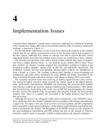
As illustrated in F igure 3-1, in the simplest OFDMA scheme (one sub-carrier per user)
each user signal is a single-carrier signal. At the base station (of, e .g., fixed wireless
access or interactive DVB-T) the received signal, being the sum of K users’ signals, acts
as an OFDM signal due to its multi-point to point nature. Unlike conventional FDMA
which requires K demodulators to handle K simultaneous users, OFDMA requires only
a single demodulator, followed by an N
c
-point DFT.
Hence, the basic components of an OFDMA transmitter at the terminal station are
FEC channel coding, mapping, sub-carrier assignment, and single carrier modulator (or
multi-carrier modulator in the case that several sub-carriers are assigned per user).
Since OFDMA is preferably used for the uplink in a multiuser environment, low-order
modulation such as QPSK with Gray mapping is preferred. However, basically high-order
modulation (e.g., 16- or 64-QAM) can also be employed.
user 0
user
K − 1
user 1
FEC
Mapping,
Rect. pulse
Mapping,
Rect. pulse
Mapping,
Rect. pulse
Modul.
f
c
Modul.
f
c
+ f
1
Modul.
f
c
+ f
K−1
Demod.
f
c
A/D
S
/
P
N
c
-Point DFT
user 0
user K − 1
user 1
TS
Base Station, BS
N
c
/T
s
K Transmitters
Receiver
TS
TS
Soft
Detect.
Soft
Detect.
Soft
Detect.
FEC
FEC
FEC
Dec.
FEC
Dec.
FEC
Dec.
Figure 3-1 Basic principle of OFDMA
Multi-Carrier FDMA 97
The sub-carrier assignment can be fixed or dynamic. In practice, in order to increase the
system robustness (to exploit frequency diversity) a dynamic assignment of sub-carriers
(i.e., frequency hopping) for each user is preferable. This approach is similar to M-or
Q-Modification in MC-CDMA (see Section 2.1.8). For pulse shaping, rectangular shaping
is usually used which results for K users in an OFDM-type signal at the receiver side.
In summary, where only one sub-carrier is assigned to a user, the modulator for the
user could be a single-carrier modulator. If several carriers are used for a given terminal
station, the modulator will be a multi-carrier (OFDM) modulator.
A very accurate clock and carrier synchronization is essential for an OFDMA system, to
ensure orthogonality between the K modulated signals originating from different terminal
stations. This can be achieved, for instance, by transmitting synchronization signals from
the base stations to all terminal stations. Therefore, each terminal station modulator derives
its carrier frequency and symbol timing from these common downlink signals.
At the base station the main components of the receiver are the demodulator (including
synchronization functions), FFT and channel decoder (with soft decisions). Since in the
case of a synchronous system the clock and carrier frequencies are readily available at
the base station (see Section 3.2.1.2), very simple carrier and clock recovery circuits are
sufficient in the demodulator to extract this information from the received signal [30].
This fact can greatly simplify the OFDM demodulator.
3.2.1.2 Synchronization Sensitivity
As mentioned before, OFDMA requires an accurate carrier spacing between different
users and precise symbol clock frequency. Hence, in a synchronous system, the OFDMA
transmitter is synchronized (clock and frequency) to the base station downlink signal,
received by all terminal stations [3][5][11].
In order to avoid time drift, the symbol clock of the terminal station is locked to
the downlink reference clock and on some extra time synchronization messages (e.g.
time stamps) transmitted periodically from the base station to all terminal stations. The
reference c lock in the base station requires a quite high accuracy [3]. Furthermore, the
terminal station can synchronize the transmit sub-carriers in phase and frequency to the
received downlink channel.
Since the clock and carrier frequencies are readily available at the reception side in
the base station, no complex carrier and clock recovery circuits are necessary in the
demodulator to extract this information from the received signal [30]. This simplifies the
OFDMA demodulator. Although the carrier frequency is locally available, there are phase
differences between different user signals and local references. These phase errors can be
compensated, for instance, by a phase equalizer which takes the form of a complex mul-
tiplier bank with one multiplier per sub-carrier. This phase equalization is not necessary
if the transmitted data is differentially encoded and demodulated.
Regarding the sensitivity to the oscillator’s phase noise, the OFDMA technique will
have the same sensitivity as an OFDM system. Therefore, low noise oscillators are needed,
particularly if the number of sub-carrier s is high or high-order modulation is used.
If each terminal station is fixed positioned (e.g., return channel of DVB-T), the ranging
procedure (i.e., measuring the delay and power of individual signals) and adjusting the
phase and the transmit power of the transmitters can be done at the installation and later on
periodically in order to cope with drifts which may be due to weather or aging variations
98 Hybrid Multiple Access Schemes
and other factors. The ranging information can be transmitted periodically from the base
station to all terminal stations within a given frame format [3][5][11].
Phase alignment of different users through ranging cannot be perfect. Residual mis-
alignment can be compensated for using a larger guard interval (cyclic extension).
3.2.1.3 Pulse Shaping
In the basic version of OFDMA, one sub-carrier is assigned to each user. The spectrum of
each user is quite narrow, which makes OFDMA more sensitive to narrowband interfer-
ence. In this section, another variant is described which may lead to increased robustness
against narrowband interference.
With rectangular pulse shaping, OFDMA has a sinc
2
(f ) shaped spectrum with over-
lapping sub-channels (see Figure 3-2a). The consequence of this is that a narrowband
interferer will affect not only one sub-carrier but several sub-carriers [31]. The robust-
ness of OFDMA to band-limited interference can be increased if the bandwidth of
individual sub-channels is strictly limited so that either adjacent sub-channels do not
overlap, or each sub-channel spectrum only overlaps with two adjacent sub-channels.
The non-overlapping concept is illustrated in Figure 3-2b. As long as the bandwidth
of one sub-channel is smaller than 1/T
s
, the narrowband interferer will only affect one
sub-channel. As shown in F igure 3-2b, the orthogonality between sub-channels is guar-
anteed, since there is no overlapping between the spectra of adjacent sub-channels. Here
a Nyquist pulse shaping is needed for ISI-free transmission on each sub-carrier, compa-
rable to a conventional single-carrier transmission scheme. This requires oversampling of
the received signal and DFT operations at a higher rate than N
c
/T
s
. In other words, the
increased robustness to narrowband interference is achieved at the expense of increased
complexity.
Rectangular
shaping
frequency
time
(b) Nyquist shaping(a) Rectangular shaping
Nyquist
shaping
Figure 3-2 Example of OFDMA with band-limited spectra
Multi-Carrier FDMA 99
The Nyquist shaping function g(t) can be implemented with a time-limited square root
raised cosine pulse with a roll-off factor α,
g(t) =
sin
πt
T
s
(1 − α)
+
4αt
T
s
cos
πt
T
s
(1 + α)
πt
T
s
1 −
4αt
T
s
2
for t ∈{−4T
s
, 4T
s
}
0otherwise
(3.8)
The relationship between T
s
,T
s
and α (roll-off factor) provides the property of the indi-
vidual separated spectra, where T
s
= (1 + α)T
s
.
3.2.1.4 Frequency Hopping OFDMA
The application of frequency hopping (FH) in an OFDMA system is straightforward.
Rather than assigning a fixed particular frequency to a given user, the base station assigns
a hopping pattern [2][11][28][36]. In the following it is assumed that N
c
sub-carriers are
available and that the frequency hopping sequence is periodic and uniformly distributed
over the signal bandwidth.
Suppose that the frequency sequence (f
0
,f
7
,f
14
, ) is assigned to the first user, the
sequence (f
1
,f
8
,f
15
, ) to the second user and so on. The frequency assignment to N
c
users can be written as
f(n,k)= f
k+(7nmodN
c
)
,k= 0, ,N
c
− 1,(3.9)
where f(n,k) designates the sub-carrier frequency assigned to user k at symbol time n.
OFDMA with frequency hopping has a close relationship with MC-CDMA. We know
that MC-CDMA is based on spreading the signal bandwidth using direct sequence spread-
ing with processing gain P
G
. In OFDMA, frequency assignments can be specified with
a code according to a frequency hopping (FH) pattern, where the number of hops can be
slow. Both schemes employ OFDM for chip transmission.
3.2.1.5 General OFDMA Transceiver
A general conceptual block diagram of an OFDMA transceiver for the uplink of a mul-
tiuser cellular system is illustrated in Figure 3-3. The terminal station is synchronized
to the base station. The transmitter of the terminal station extracts from the demodu-
lated downlink r eceived data MAC messages on information about sub-carrier allocation,
frequency hopping pattern, power control messages and timing, and further clock and fre-
quency synchronization information. Synchronization of the terminal station is a chieved
by using the MAC control messages to perform time synchronization and using frequency
information issued from the terminal station downlink demodulator (the recovered base
station system clock). The MAC control messages are processed by the MAC management
block to instruct the terminal station modulator on the transmission resources assigned to
100 Hybrid Multiple Access Schemes
- Sub-carrier allocation
- Timing
- Power control, Ranging
Synchronization
Interleaving
Encoding
Symbol mapping
Framing
Multi-carrier modulator
(IFFT)
Multi-carrier demodulator
(FFT)
Sub-carrier shaping
RF up-converter
RF down-converter
RF
output
Pilot
insertion
Medium Access Controller
Channel
estimation
Synchronization
Matched filtering
Equalization, Demapping
Deinterleaving, Decoding
RF
input
Base Station
OFDMA Receiver
BS Transmitter
Terminal Station
OFDMA Transmitter
TS Receiver
Clock,
frequency
MAC
messages
Clock,
frequency
Downlink
Uplink
MAC
Figure 3-3 General OFDMA conceptual transceiver
it and to tune the access performed to the radio frequency channel. The pilot symbols are
inserted to ease the channel estimation task at the base station.
At the base station, the received signals issued by all terminal stations are demodulated
by the use of an FFT as an OFDM receiver, assisted by the MAC layer manage-
ment block.
It should be emphasized that the transmitter and the receiver structure of an OFDMA
system is quite similar to an OFDM system. Same components like FFT, channel estima-
tion, equalization and soft channel decoding can be used for both cases.
In order to offer a variety of multimedia services requiring different data rates, the
OFDMA scheme needs to be fl exible in terms of data rate assignment. This can be
achieved by assigning the required number of sub-carriers according to the request
of a given user. This method of assignment is part of a MAC protocol at the base
station.
Note that if the number of assigned sub-carriers is an integer power of two, the inverse
FFT can be used at the terminal station transmitter, which will be equivalent to a con-
ventional OFDM transmitter.
3.2.2 OFDMA with Code Division Multiplexing: SS-MC-MA
The extension of OFDMA by code division multiplexing (CDM) results in a multi-
ple access scheme referred to as spread spectrum multi-carrier multiple access (SS-
MC-MA) [18][19]. It applies OFDMA for user separation and additionally uses CDM
on data symbols belonging to the same user. The CDM component is introduced in
order to achieve additional diversity gains. Like MC-CDMA, SS-MC-MA exploits the
Multi-Carrier FDMA 101
advantages given by the combination of the spread spectrum technique and multi-carrier
modulation. The SS-MC-MA scheme is similar to the MC-CDMA transmitter with M-
Modification. Both transmitters are identical except for the mapping of the user data to
the subsystems. In SS-MC-MA systems, one user maps L data symbols to one sub-
system which this user exclusively uses for transmission. Different users use differ-
ent subsystems in SS-MC-MA systems. In MC-CDMA systems, M data symbols per
user are mapped to M different subsystems where each subsystem is shared by dif-
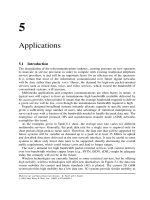
ferent users. The principle of SS-MC-MA is illustrated for a downlink transmitter in
Figure 3-4.
The SS-MC-MA and MC-CDMA systems have the following similarities:
— SS-MC-MA and MC-CDMA systems exploit frequency diversity by spreading each
data symbol over L sub-carriers.
— Per subsystem, the same data detection techniques can be applied with both SS-MC-
MA and MC-CDMA systems.
— ISI and ICI can be avoided in SS-MC-MA and MC-CDMA systems, resulting in
simple data detection techniques.
However, their main differences are:
— In SS-MC-MA systems, CDM is used for the simultaneous transmission of the data
of one user on the same sub-carriers, whereas in MC-CDMA systems, CDM is used
for the transmission of the data of different users on the same sub-carriers. Therefore,
SS-MC-MA is an OFDMA scheme on a sub-carrier level, whereas MC-CDMA is a
CDMA scheme.
— MC-CDMA systems have to cope with multiple access interference, which is not
present in SS-MC-MA systems. Instead of multiple access interference, SS-MC-MA
systems have to cope with self-interference caused by the superposition of signals
from the same user.
frequency interleaving/hopping
L − 1 N
c
− 1
L − 1
0
0
L data symbols
of user 0
L data symbols
of user K − 1
0
spreader
c
(0)
spreader
c
(0)
OFDM
d
0
(0)
d
L−1
(0)
0
d
(
K−1
)
x
serial-to-parallel
converter
serial-to-parallel
converter
+
+
spreader
c
(L−1)
spreader
c
(L−1)
L−1
d
(
K−1
)
s
(K−1)
s
(0)
Figure 3-4 SS-MC-MA downlink transmitter
102 Hybrid Multiple Access Schemes
— In SS-MC-MA systems, each sub-carrier is exclusively used by one user, enabling
low complex channel estimation especially for the uplink. In MC-CDMA systems, the
channel estimation in the uplink has to cope with the superposition of signals from
different users which are faded independently on the same sub-carriers, increasing the
complexity of the uplink channel estimation.
After this comparative introduction of SS-MC-MA, the uplink transmitter and the assigned
receiver are described in detail in this section.
Figure 3-5 shows an SS-MC-MA uplink transmitter with channel coding for the data
of user k. The vector
d
(k)
= (d
(k)
0
,d
(k)
1
, ,d
(k)
L−1
)
T
(3.10)
represents one block of L parallel converted data symbols of user k. Each data symbol
is multiplied with another orthogonal spreading code of length L.TheL × L matrix
C = (c
0
, c
1
, ,c
L−1
)(3.11)
represents the L different spreading codes c
l
,l = 0, ,L− 1, used by user k.The
spreading matrix C can be the same for all users. The modulated spreading codes are
synchronously added, resulting in the transmission vector
s
(k)
= Cd
(k)
= (S
(k)
0
,S
(k)
1
, ,S
(k)
L−1
)
T
.(3.12)
To increase the robustness of SS-MC-MA systems, less than L data modulated spreading
codes can be added in one transmission vector s
(k)
.
Comparable to frequency interleaving in MC-CDMA systems, the SS-MC-MA trans-
mitter performs a user-specific frequency mapping such that subsequent chips of s
(k)
are
interleaved over the whole transmission bandwidth. The user-specific frequency mapping
assigns each user exclusively its L sub-carriers, avoiding multiple access interference.
The Q-Modification introduced in Section 2.1.8.2 for MC-CDMA systems is inherent
in SS-MC-MA systems. M-Modification can, as in MC-CDMA systems, be applied to
SS-MC-MA systems by assigning a user more than one subsystem.
OFDM with guard interval is applied in SS-MC-MA systems in the same way as in
MC-CDMA systems. In order to perform coherent data detection at the receiver and to
L−1
0
OFDM
with
user specific
frequency
mapper
+
serial-to-parallel
converter
serial-to-parallel
converter
d
(k)
s
(k)
x
symbol-
mapper
inter-
leaver
channel
encoder
data source
of user k
pilot symbol
generator
spreader
c
(0)
spreader
c
(L−1)
Figure 3-5 SS-MC-MA t ransmitter of user k
Multi-Carrier FDMA 103
L − 1
0
yr
(k)
.
parallel-to-serial
converter
deinter-
leaver
channel
decoder
data sink
of user k
inverse
OFDM
with
user-specific
frequency
demapper
detector
and
symbol demapper
with LLR output
channel
estimator
Figure 3-6 SS-MC-MA receiver of user k
guarantee robust time and frequency synchronization, pilot symbols are multiplexed in
the transmitted data.
An SS-MC-MA receiver with coherent detection of the data of user k is shown in
Figure 3-6. After inverse OFDM with user-specific frequency demapping and extraction
of the pilot symbols from the symbols with user data, the received vector
r
(k)
= H
(k)
s
(k)
+ n
(k)
= (R
(k)
0
,R
(k)
1
, ,R
(k)
L−1
)
T
(3.13)
with the data of user k is obtained. The L × L diagonal matrix H
(k)
and the vector
n
(k)
of length L describe the channel fading and noise, respectively, on the sub-carriers
exclusively used by user k.
Any of the single-user or multiuser detection techniques presented for MC-CDMA
systems in Section 2.1.5 can be applied for the detection of the data of a single user
per subsystem in SS-MC-MA systems. However, SS-MC-MA systems offer (especially
in the downlink) the advantage that with multi-symbol detection (equivalent to mul-
tiuser detection in MC-CDMA systems) in one estimation step simultaneously L data
symbols of a single user are estimated. Compared to MC-CDMA systems, the com-
plexity per data symbol of multi-symbol detection in SS-MC-MA systems reduces by
a factor of L in the downlink. With multi-symbol detection, LLRs can inherently be
obtained from the detection algorithm which may also include the symbol demapping.
After deinterleaving and decoding of the LLRs, the detected source bits of user k are
obtained.
A promising future mobile radio system may use MC-CDMA in the downlink and SS-
MC-MA in the uplink. This combination achieves for both links a high spectral efficiency
and flexibility. Furthermore, in both links the same hardware can be used, only the user
data have to be mapped differently [16]. Alternatively, a modified SS-MC-MA scheme
with flexible resource allocation can achieve a high throughput in the downlink [24].
SS-MC-MA can cope with a certain amount of asynchronism. It has been shown in [21]
and [22] that it is possible to avoid any additional measures for uplink synchroniza-
tion in cell radii up to several kilometers. The principle is to apply a synchronized
downlink and each user transmits in the uplink directly after he has received its data
without any additional time correction. A guard time shorter than the maximum time
difference between the user signals is used, which increases the spectral efficiency of
the system. Thus, SS-MC-MA can be achieved with a low-complex synchronization in
the uplink.
104 Hybrid Multiple Access Schemes
Moreover, the SS-MC-MA scheme can be modified such that with not fully loaded
systems, the additional available resources are used for more reliable transmission [6][7].
With a full load, these BER performance improvements can only be obtained by reducing
the spectral efficiency of the system.
3.2.3 Interleaved FDMA (IFDMA)
The multiple access scheme IFDMA is based on the principle of FDMA where no mul-
tiple access interference occurs [34][35]. The signal is designed in such a way that the
transmitted signal can be considered a multi-carrier signal where each user is exclusively
assigned a sub-set of sub-carriers. The sub-carriers of the different users are interleaved.
It is an inherent feature of the IFDMA signal that the sub-carriers of a user are equally
spaced over the transmission bandwidth B, which guarantees a maximum exploitation of
the available frequency diversity. The signal design of IFDMA is performed in the time
domain and the resulting signal has the advantage of a low PAPR. However, IFDMA
occupies a larger transmission bandwidth compared to the rectangular type spectrum with
OFDM, which reduces the spectral efficiency.
The transmission of IFDMA signals in multipath channels results in ISI which requires
more complex receivers than multi-carrier systems designed in the frequency domain.
Compared to MC-CDMA, an IFDMA scheme is less flexible, since it does not support
adaptive sub-carrier allocation and sub-carrier loading.
The IFDMA signal design is illustrated in Figure 3-7. A block of Q data symbols
d
(k)
= (d
(k)
0
,d
(k)
1
, ,d
(k)
Q−1
)
T
(3.14)
assigned to user k is used for the construction of one IFDMA symbol. The duration of a
data symbol is T and the duration of an IFDMA symbol is
T
s
= QT .(3.15)
In order to limit the effect of ISI to one IFDMA symbol, a guard interval consisting of a
cyclic extension of the symbol is included between adjacent IFDMA symbols, comparable
d
0
d
0
d
1
d
2
d
1
d
0
d
1
d
0
d
1
d
Q − 1
d
Q − 1
d
0
d
1
d
0
d
1
d
Q − 1
d
Q − 1
d
Q − 1
d
Q − 1
T
s
′ = QT
Q T
c
L Q T
c
L
g
Q T
c
T
Figure 3-7 IFDMA signal design with guard interval
Multi-Carrier TDMA 105
to the guard interval in multi-carrier systems. Each IFDMA symbol of duration T
s
includes
the guard interval of duration
T
g
= L
g
QT
c
.(3.16)
An IFDMA symbol is obtained by compressing each of the Q symbols from symbol
duration T to chip duration T
c
, i.e.,
T
c
=
T
L
g
+ L
,(3.17)
and repeating the resulting compressed block (L
g
+ L) times. Thus, the transmission
bandwidth is spread by the f actor
P
G
= L
g
+ L. (3.18)
The compressed vector of user k can be written as
s
(k)
=
1
L
g
+ L
d
(k)
T
, d
(k)
T
, ,d
(k)
T
(L
g
+L)copies
T
.(3.19)
The transmission signal x
(k)
is constructed by element-wise multiplication of the com-
pressed vector s
(k)
with a user-dependent phase vector c
(k)
of length (L
g
+ L)Q having
the components
c
(k)
l
= e
−j 2πlk/(QL)
,l= 0, ,(L
g
+ L)Q − 1.(3.20)
The element-wise multiplication of the two vectors s
(k)
and c
(k)
ensures that each user
is assigned a set of sub-carriers orthogonal to the sub-carrier sets of all other users. Each
sub-carrier set contains Q sub-carriers and the number of active users is restricted to
K
L. (3.21)
The IFDMA receiver has to perform an equalization to cope with the ISI which is
present with IFDMA in multipath channels. For low numbers of Q, the optimum maxi-
mum likelihood sequence estimation can be applied with reasonable complexity whereas
for higher numbers of Q, less complex suboptimum detection techniques such as linear
equalization or decision feedback equalization are required to deal with the ISI.
Due to its low PAPR, a practical application of IFDMA can be an uplink where power-
efficient terminal stations are required which benefit from the constant envelope and more
complex receivers which have to cope with ISI are part of the base station.
3.3 Multi-Carrier TDMA
The combination of OFDM and TDMA is referred to as MC-TDMA or OFDM-TDMA.
Due to its well understood TDMA component, MC-TDMA has achieved success and
it is currently part of several high-rate wireless LAN standards, e.g., IEEE 802.11a/g/h,
ETSI HIPERLAN/2, and MMAC, and is also part of the IEEE 802.16a and draft ETSI-
HIPERMAN WLL standards [4][5][10][11] (see Chapter 5).
106 Hybrid Multiple Access Schemes
MC-TDMA transmission is done in a frame manner like in a TDMA system. One time
frame within MC-TDMA has K time slots (or bursts), each allocated to one of the K
terminal stations. One time slot/burst consists of one or several OFDM symbols. The
allocation of time slots to the terminal stations is controlled by the base station medium
access controller (MAC). Multiple access interference can be avoided when ISI between
adjacent OFDM symbols can be prevented by using a sufficiently long guard interval or
with a timing advance control mechanism.
Adaptive coding and modulation is usually applied in conjunction with MC-TDMA
systems, where the coding and modulation can be easily adapted per transmitted burst.
The main advantages of MC-TDMA are in guaranteeing a high peak data rate, in its
multiplexing gain (bursty transmission), in the absence of multiple access interference
and in simple receiver structures that can be designed, for instance, by applying differ-
ential modulation in the frequency direction. In case of coherent demodulation a quite
robust OFDM burst synchronization is needed, especially for the uplink. A frequency syn-
chronous system where the terminal station transmitter is frequency-locked to the received
signal in the downlink or spending a high amount of overhead transmitted per burst could
remedy this problem.
Besides the complex synchronization mechanism required for an OFDM system, the
other disadvantage of MC-TDMA is that diversity can only be exploited by using addi-
tional measures like channel coding or applying multiple transmit/receive antennas. As
a TDMA system, the instantaneous transmitted power in the terminal station is high,
which requires more powerful high power amplifiers than for FDMA systems. Further-
more, the MC-TDMA system as an OFDM system needs a high output power back-
off.
As shown in Figure 3-8, the terminal station of an MC-TDMA system is synchronized
to the base station in order to reduce the synchronization overhead. The transmitter of
the terminal station extracts from the demodulated downlink data such as MAC messages
burst allocation, power control and timing advance, and further clock and frequency
synchronization information. In other w ords, the synchronization of the terminal sta-
tion is achieved using the MAC control messages to perform time synchronization and
using frequency information issued from the terminal station downlink demodulator (the
recovered base station system clock). MAC control messages are processed by the MAC
management block to instruct the terminal station modulator on the transmission resources
assigned to it and to tune the access. Here, the pilot/reference symbols are inserted at the
transmitter side to ease the burst synchronization and channel estimation tasks at the base
station. At the base station, the received burst, issued by each terminal station, is detected
and multi-carrier demodulated.
It should be emphasized that the transmitter and receiver structure of an MC-TDMA
system is quite similar to an OFDM/OFDMA system. The same components, such as FFT,
channel estimation, equalization and soft channel decoding, can be used for both, except
that for an MC-TDMA system a burst synchronization is required, equivalent to a single-
carrier TDMA system. Furthermore, a frequency synchronous system would simplify the
MC-TDMA receiver synchronization tasks.
Combining OFDMA and MC-TDMA achieves a flexible multiuser system with high
throughput [9].
Ultra Wide Band Systems 107
MAC
- Time burst allocation,
- Power control, Ranging
Synchronization
Interleaving,
Encoding
Symbol mapping
Multi-carrier modulator
(IFFT)
Multi-carrier demodulator
(IFFT)
TDMA burst formatting
D/A & RF
RF & A/D
RF
output
Pilot/Ref.
insertion
Medium Access Controller
(MAC)
Channel
estimation
Synchronization
Burst synchronization
Equalization, Demapping
Deinterleaving, Decoding
RF
input
Base Station
MC-TDMA Receiver
BS Transmitter
Terminal Station
MC-TDMA Transmitter
TS Receiver
Clock,
frequency
MAC
messages
Clock,
frequency
Downlink
Uplink
Figure 3-8 General MC-TDMA conceptual transceiver
3.4 Ultra Wide Band Systems
The technique for generating an ultra wide band (UWB) signal has existed for more than
three decades [27], which is better known to the radar community as a baseband carrier
less short pulse [1].
A classical way to generate an UWB signal is to spread the data with a code with
a very large processing gain, i.e., 50 to 60 dB, resulting in a transmitted bandwidth of
several GHz. Multiple access can be realized by classical CDMA where for each user a
given spreading code is assigned. However, the main problem of such a technique is its
implementation complexity.
As the power spectral density of the UWB signal is extremely low, the transmitted
signal appears as a negligible white noise for other systems. In the increasingly c rowded
spectrum, the transmission of the data as a noise-like signal can be considered a main
advantage for the UWB systems. However, its drawbacks are the small coverage and the
low data rate for each user. Typically for short-range application (e.g., 100 m), the data
rate assigned to each user can be about several kbit/s.
In [25] and [37] an alternative approach compared to classical CDMA is proposed for
generating a UWB signal that does require sine-wave generation. It is based on time-
hopping spread spectrum. The key advantages of this method are the ability to resolve
multiple paths and the low complexity technology availability for its implementation.
3.4.1 Pseudo-Random PPM UWB Signal Generation
The idea of generating a UWB signal by transmitting ultra-short Gaussian monocycles
with controlled pulse-to-pulse intervals can be found in [25]. The monocycle is a wideband
108 Hybrid Multiple Access Schemes
signal with center frequency and bandwidth completely dependent of the monocycle dura-
tion. In the time domain, a Gaussian monocycle is derived by the first derivative of the
Gaussian function given by
s(t) = 6a
eπ
3
t
τ
e
−6π
t
τ
2
,(3.22)
where a is the peak amplitude of the monocycle and τ is the monocycle duration. In the
frequency domain, the monocycle spectrum is given by
S(f) =−j
2fτ
2
3
eπ
2
e
−
π
6
(f τ)
2
,(3.23)
with center frequency and bandwidth approximately equal to 1/τ .
In Figure 3-9, a Gaussian monocycle with τ = 0.5 ns duration is illustrated. This mono-
cycle will result in a center frequency of 2 GHz with 3 dB bandwidth of approximately
2 GHz (from 1 GHz to 3.16 GHz). For data transmission, pulse position modulation
(PPM) can be used, which varies the precise timing of transmission of a monocycle
about the nominal position. By shifting each monocycle’s actual transmission time over
a large time frame in accordance with a specific PN code, i.e., performing time hopping
(see Figure 3-10), this pseudo-random time modulation makes the UWB spectrum a pure
white noise in the frequency domain. In the time domain each user will have a unique
PN time-hopping code, hence resulting in a time-hopping multiple access.
A single data bit is generally spread over multiple monocycles, i.e., pulses. The duty
cycle of each transmitted pulse is about 0.5–1%. Hence, the processing gain obtained
by this technique is the sum of the duty cycle (ca. 20–23 dB) and the number of pulses
used per data bit. As an example, if we consider a transmission with 10
6
pulses per
second with a duty cycle of 0.5% and with a pulse duration of 0.5 ns (B = 2 GHz
bandwidth), for 8 kbit/s transmitted data the resulting processing gain will be 54 dB,
which is significantly high.
time
Amplitude
t = 0.5 nsec
Figure 3-9 Gaussian monocycle with duration 0.5 ns
Ultra Wide Band Systems 109
Time
Amplitude
T
n
T
n+1
T
n+2
T
n+3
T
n+4
T
n+5
Figure 3-10 PN time modulation with 5 pulses
The ultra wide band signal generated above can be seen as a combination of spread
spectrum with pulse position modulation.
3.4.2 UWB Transmission Schemes
A UWB transmission scheme for a multiuser environment is illustrated in Figure 3-11,
where for each user a given time-hopping pattern, i.e., PN code, is assigned. The trans-
mitter is quite simple. It does not include any amplifier or any IF generation. The signal
of the transmitted data after pulse position modulation according to the user’s PN code is
emitted directly at the Tx antenna. A critical point of the transmitter is the antenna which
may act as a filter.
.
.
.
K Correlators
or Rakes
Baseband
processing
Pulse
generat.
Program.
delay
Program.
delay
PN code
user 0
Synch.
Data
user 0
Data
user
K − 1
TS Transmitter
TS Transmitter BS Receiver
PN code
user K − 1
Antenna
Pulse
generat.
PN code
user K − 1
Synch.
Data
user 0
Data
user
K − 1
.
.
.
. . .
K− 1
0
Mod.
PN code
user 0
Prog.
delay
Pulse
generat.
Antenna
Mod.
Prog.
delay
Pulse
generat.
Antenna
Figure 3-11 Multiuser UWB transmission scheme
110 Hybrid Multiple Access Schemes
The receiver components are similar to the transmitter. A rake receiver as in a con-
ventional DS-CDMA system might be required to cope with multipath propagation. The
baseband signal processing extracts the modulated signal and controls both signal acqui-
sition and tracking.
The main application fields of UWB could be short range (e.g., indoor) multiuser
communications, radar systems, and location determination/positioning. UWB may have
a potential application in the automotive industry.
3.5 Comparison of Hybrid Multiple Access Schemes
A multitude of performance comparisons have been carried out between MC-CDMA and
DS-CDMA as well as between the multi-carrier multiple access schemes MC-CDMA,
MC-DS-CDMA, SS-MC-MA, OFDMA and MC-TDMA. It has been shown that MC-
CDMA can significantly outperform DS-CDMA with respect to BER performance and
bandwidth efficiency in the synchronous downlink [8][13][14]. The reason for better per-
formance with MC-CDMA is that it can avoid ISI and ICI, allowing an efficient, simple
user signal separation. The results of these comparisons are the motivation to consider
MC-CDMA as a potential candidate for a future 4G mobile radio system which should
outperform 3G systems based on DS-CDMA.
The design of a future air interface for broadband mobile communications requires
a comprehensive comparison between the various multi-carrier based multiple access
schemes. In Section 2.1.9, the performance of MC-CDMA, OFDMA, and MC-TDMA has
been compared in a Rayleigh fading channel for scenarios with and without FEC channel
coding, where different symbol mapping schemes have also been taken into account. It
can generally be said that MC-CDMA outperforms the other multiple access schemes but
requires additional complexity for signal spreading and detection. The reader is referred
to Section 2.1.9 and to [15][17][23][26][29] to directly compare the performance of the
various schemes.
In the following, we show a performance comparison between MC-CDMA and OFDMA
for the downlink and between SS-MC-MA and OFDMA for the uplink. The transmission
bandwidth is 2 MHz and the carrier frequency is 2 GHz. The guard interval exceeds
the maximum delay of the channel. The mobile radio channels are chosen according to
the COST 207 models. Simulations are carried out with a bad urban (BU) profile and a
velocity of 3 km/h of the mobile user and with a hilly terrain (HT) profile and a velocity
of 150 km/h of the mobile user. QPSK is chosen for symbol mapping. All systems are
fully loaded and synchronized.
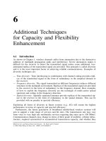
In Figure 3-12, the BER versus the SNR per bit for MC-CDMA and OFDMA systems
with different channel code rates in the downlink is shown. The number of sub-carriers is
512. Perfect channel knowledge is assumed in the receiver. The results for MC-CDMA are
obtained with soft interference cancellation [20] after the 1st iteration. It can be observed
that MC-CDMA outperforms OFDMA. The SNR gain with MC-CDMA compared to
OFDMA strongly depends on the propagation scenario and code rate.
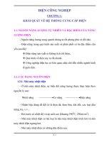
Figure 3-13 shows the BER versus the SNR per bit of a n SS-MC-MA system and
an OFDMA system in the uplink. The number of sub-carriers is 256. Both systems
apply one-dimensional channel estimation which requires an overhead on pilot symbols of
22.6%. The channel code rate is 2/3. The SS-MC-MA system applies maximum likelihood
Comparison of Hybrid Multiple Access Schemes 111
MC-CDMA, R = 1/2, HT 150 kmh
MC-CDMA, R = 1/2, BU 3 km/h
MC-CDMA, R = 2/3, HT 150 km/h
MC-CDMA, R = 2/3, BU 3 km/h
OFDMA, R = 1/2, HT 150 km/h
OFDMA, R = 1/2, BU 3 km/h
OFDMA, R = 2/3, HT 150 km/h
OFDMA, R = 2/3, BU 3 km/h
4567891011121314153
E
b
/N
0
in dB
10
−3
10
−2
10
−1
10
0
10
−4
BER
Figure 3-12 BER versus SNR of MC-CDMA and OFDMA in the downlink; QPSK; fully loaded
system
8
E
b
/N
0
in dB
10
−5
9 101112131415161718192021
SS-MC-MA, HT 150 km/h
SS-MC-MA, BU 3 km/h
OFDMA, HT 150 km/h
OFDMA, BU 3 kmh
10
−4
10
−4
BER
10
−2
10
−1
10
0
Figure 3-13 BER versus SNR of SS-MC-MA and OFDMA with one-dimensional pilot symbol
aided channel estimation in the uplink; R = 2/3; QPSK; fully loaded system
112 Hybrid Multiple Access Schemes
detection. The performance of SS-MC-MA can be further improved by applying soft
interference cancellation in the receiver. The SS-MC-MA system outperforms OFDMA
in the uplink, however, it r equires more complex receivers. The SS-MC-MA system and
the OFDMA system would improve in performance by about 1 dB in the downlink due
to reduced overheads with two-dimensional channel estimation.
3.6 References
[1] Bennett C.L. and Ross G.F., “Time-domain electromagnetics and its applications,” Proceedings IEEE,
vol. 66, pp. 299–318, March 1978.
[2] Chen Q., Sousa E.S. and Pasupathy S., “Multi-carrier CDMA with adaptive frequency hopping for mobile
radio systems,” IEEE Journal on Selected Areas in Communications, vol. 14, pp. 1852–1858, Dec. 1996.
[3] ETSI DVB-RCT (TS 301 958), “Interaction channel for digital terrestrial television (RCT) incorporating
multiple access OFDM,” Sophia Antipolis, France, March 2001.
[4] ETSI HIPERLAN (TS 101 475), “Broadband radio access networks HIPERLAN Type 2 functional spec-
ification – Part 1: Physical layer,” Sophia Antipolis, France, Sept. 1999.
[5] ETSI HIPERMAN (Draft TS 102 177), “High performance metropolitan area network, Part 1: Physical
layer,” Sophia Antipolis, France, Feb. 2003.
[6] Giannakis G.B., Anghel P.A., Wang Z. and Scaglione A., “Generalized multi-carrier CDMA for MUI/ISI-
resilient uplink transmissions irrespective of frequency-selective multipath,” in Proc. International Work-
shop on Multi-Carrier Spread-Spectrum & Related Topics (MC-SS’99), Oberpfaffenhofen, Germany,
pp. 25–33, Sept. 1999.
[7] Giannakis G.B., Stamoulis A., Wang Z. and Anghel A., “Load-adaptive MUI/ISI-resilient generalized
multi-carrier CDMA with linear and DF receivers,” European Transactions on Telecommunications (ETT),
vol. 11, pp. 527–537, Nov./Dec. 2000.
[8] Hara S. and Prasad R., “Overview of multi-carrier CDMA,” IEEE Communications Magazine, vol. 35,
pp. 126–133, Dec. 1997.
[9] Ibars C. and Bar-Ness Y., “Rate-adaptive coded multi-user OFDM for downlink wireless systems,” in
Proc. International Workshop on Multi-Carrier Spread-Spectrum & Related Topics (MC-SS 2001),Oberp-
faffenhofen, Germany, pp. 199–207, Sept. 2001.
[10] IEEE-802.11 (P802.11a/D6.0), “LAN/MAN specific requirements – Part 2: Wireless MAC and PHY spec-
ifications – high speed physical layer in the 5 GHz band,” IEEE 802.11, May 1999.
[11] IEEE 802.16ab-01/01, “Air interface for fixed broadband wireless access systems – Part A: Systems
between 2 and 11 GHz,” IEEE 802.16, June 2000.
[12] Jankiraman M. and Prasad R., “Wideband multimedia solution using hybrid CDMA/OFDM/SFH tech-
niques,” in Proc. International Workshop on Multi-Carrier Spread-Spectrum & Related Topics (MC-SS’99),
Oberpfaffenhofen, Germany, pp. 15–24, Sept. 1999.
[13] Kaiser S., “OFDM-CDMA versus DS-CDMA: Performance evaluation in fading c hannels,” in Proc. IEEE
International Conference on Communications (ICC‘95), Seattle, USA, pp. 1722– 1726, June 1995.
[14] Kaiser S., “On the performance of different detection techniques for OFDM-CDMA in fading channels,” in
Proc. IEEE Global Telecommunications Conference (GLOBECOM’95), Singapore, pp. 2059–2063, Nov.
1995.
[15] Kaiser S., “Trade-off between channel coding and spreading in multi-carrier CDMA systems,” in Proc.
IEEE International Symposium on Spread Spectrum Techniques and Applications (ISSSTA’96),Mainz,
Germany, pp. 1366 –1370, Sept. 1996.
[16] Kaiser S., Multi-Carrier CDMA Mobile Radio S ystems – Analysis and Optimization of Detection, Decod-
ing, and Channel Estimation.D
¨
usseldorf: VDI-Verlag, Fortschritt-Berichte VDI, series 10, no. 531, 1998,
PhD thesis.
[17] Kaiser S., “MC-FDMA and MC-TDMA versus MC-CDMA and SS-MC-MA: Performance evaluation for
fading channels,” in Proc. IEEE International Symposium on Spread Spectrum Techniques and Applications
(ISSSTA’98), Sun City, South Africa, pp. 115–120, Sept. 1998.
[18] Kaiser S. and Fazel K., “A spread-spectrum multi-carrier multiple-access system for mobile communica-
tions,” in Proc. International Workshop on Multi-Carrier Spread-Spectrum (MC-SS’97), Oberpfaffenhofen,
Germany, pp. 49 –56, April 1997.
References 113
[19] Kaiser S. and Fazel K., “A flexible spread spectrum multi-carrier multiple-access system for multi-media
applications,” in Proc. IEEE International Symposium on Personal, Indoor and Mobile Communications
(PIMRC’97), Helsinki, Finland, pp. 100–104, Sept. 1997.
[20] Kaiser S. and Hagenauer J., “Multi-carrier CDMA with iterative decoding and soft-interference cancella-
tion,” in Proc. IEEE Global Telecommunications Conference (GLOBECOM’97), Phoenix, USA, pp. 6–10,
Nov. 1997.
[21] Kaiser S. and Krzymien W.A., “Performance effects of the uplink asynchronism in a spread spectrum
multi-carrier multiple access system,” European Transactions on Telecommunications (ETT), vol. 10,
pp. 399–406, July/Aug. 1999.
[22] Kaiser S., Krzymien W.A. and Fazel K., “SS-MC-MA systems with pilot symbol aided channel estimation
in the asynchronous uplink,” European Transactions on Telecommunications (ETT), vol. 11, pp. 605–610,
Nov./Dec. 2000.
[23] Lindner J., “On coding and spreading for MC-CDMA,” in Proc. International Workshop on Multi-Carrier
Spread-Spectrum & Related Topics (MC-SS’99), Oberpfaffenhofen, Germany, pp. 89–98, Sept. 1999.
[24] Novak R. and Krzymien W.A., “A downlink SS-OFDM-F/TA packet data system employing multi-user
diversity,” in Proc. International Workshop on Multi-Carrier Spread-Spectrum & Related Topics (MC-SS
2001), Oberpfaffenhofen, Germany, pp. 181–190, Sept. 2001.
[25] Petroff A. and Withington P., “Time modulated ultra-wideband (TM-UWB) overview,” in Proc. Wireless
Symposium 2000, San Jose, USA, Feb. 2000.
[26] Rohling H. and Gr
¨
unheid R., “Performance comparison of different multiple access schemes for the down-
link of an OFDM communication system,” in Proc. IEEE Vehicular Technology Conference (VTC’97),
Phoenix, USA, pp. 1365–1369, May 1997.
[27] Ross G.F., “The transient analysis of certain TEM mode four-post networks,” IEEE Transactions on
Microwave Theory and Techniques, vol. 14, pp. 528–542, Nov. 1966
[28] Sari H., “Orthogonal frequency-division multiple access with frequency hopping and diversity,” in Proc.
International Workshop on Multi-Carrier Spread-Spectrum (MC-SS’97), Oberpfaffenhofen, Germany,
pp. 57–68, April 1997.
[29] Sari H., “A review of multi-carrier CDMA,” in Proc. International Workshop on Multi-Carrier Spread-
Spectrum & Related Topics (MC-SS 2001), Oberpfaffenhofen, Germany, pp. 3–12, Sept. 2001.
[30] Sari H. and Karam G., “Orthogonal frequency-division multiple access and its application to CATV net-
works,” European Transactions on Telecommunications (ETT), vol. 9, pp. 507–516, Nov./Dec. 1998.
[31] Sari H., Levy Y. and Karam G., “Orthogonal frequency-division multiple access for the return channel on
CATV networks,” in Proc. International Conference on Telecommunications (ICT’96), Istanbul, Turkey,
pp. 52–57, April 1996.
[32] Sari H., Levy Y. and Karam G., “OFDMA –A new multiple access technique and its application to interac-
tive CATV networks,” in Proc. European Conference on Multimedia Applications, Services and Techniques
(ECMAST ’96), Louvain-la-Neuve, Belgium, pp. 117–127, May 1996.
[33] Sari H., Vanhaverbeke F. and Moeneclaey M., “Some novel concepts in multiplexing and multiple access,”
in Proc. International Workshop on Multi-Carrier Spread-Spectrum & Related Topics (MC-SS’99),Oberp-
faffenhofen, Germany, pp. 3–12, Sept. 1999.
[34] Schnell M., De Broeck I. and Sorger U., “A promising new wideband multiple access scheme for future
mobile communications systems,” European Transactions on Telecommunications (ETT), vol. 10,
pp. 417–427, July/Aug. 1999.
[35] Sorger U., De Broeck I. and Schnell S., “Interleaved FDMA – a new spread-spectrum multiple
access scheme,” in Proc. IEEE International Conference on Communications (ICC’98), Atlanta, USA,
pp. 1013–1017, June 1998.
[36] Tomba L. and Krzymien W.A., “An OFDM/SFH-CDMA transmission scheme for the uplink,” in Proc.
International Workshop on Multi-Carrier Spread-Spectrum (MC-SS’97), Oberpfaffenhofen, Germany,
pp. 203–210, April 1997.
[37] Win M.Z. and Scholtz R.A., “Ultra-wideband bandwidth time-hopping spread-spectrum impulse radio for
wireless multiple access communications,” IEEE Transactions on Communications, vol. 48, pp. 679–691,
April 2000.