Tài liệu Điện thoại di động giao thức viễn thông cho các mạng dữ liệu P2 pdf
Bạn đang xem bản rút gọn của tài liệu. Xem và tải ngay bản đầy đủ của tài liệu tại đây (657.78 KB, 21 trang )
2
Mobile agent-based service
implementation, middleware,
and configuration
There are two agents groups: I ntelligent Agents and Mobile Agents (MAs). Intelligent
Agents have the ability to learn and react. MAs can migrate between different hosts,
execute certain tasks, and collaborate with other agents.
In the Intelligent Network (IN) architecture, the control of the network resources is
performed by the signaling plane, whereas the service creation, deployment, and provi-
sioning is performed by the service plane. This separation allows introduction of new
services and service features without changing the basic functionality of the network for
the establishment and the release of resources such as calls and connections.
Traffic in the signaling network is reduced by moving services closer to the cus-
tomers, and the messages related to servic e control are handled locally. The overhead of
downloading service programs is done off-line and does not impact signaling performance.
MAs enable both temporal distribution (i.e., distribution over time) and spatial distri-
bution (i.e., distribution over different network nodes) of service logic.
MAs can be implemented in Java programming language. Additional features and
mechanisms supported a nd envisioned in Jini programming language allow for imple-
mentation of mobile devices in practical systems.
2.1 AGENT-BASED SERVICE IMPLEMENTATION
Distributed Object Technology (DOT) provides a Distributed Processing Environment
(DPE) to enable designers to create object-oriented distributed applications, which are not
necessarily aware of the physical layout of the underlying network structure hidden by
platform services. DOT-based specifications of DPEs, like CORBA 2.0, have been adopted
Mobile Telecommunications Protocols For Data Networks. Anna Ha
´
c
Copyright
2003 John Wiley & Sons, Ltd.
ISBN: 0-470-85056-6
12 MOBILE AGENT-BASED SERVICE IMPLEMENTATION, MIDDLEWARE, AND CONFIGURATION
by the Telecommunications Information Networking Architecture (TINA) Consortium as
the basis for the distributed architecture.
Mobile Agent Technology (MAT) uses the capabilities provided by machine-indepen-
dent, interpreted languages like Java to deploy a framework in which applications can
roam between network nodes maintaining their execution status. MAT platforms are often
based on a CORBA DPE layer that allows distributed applications to dynamically recon-
figure their layout according, for instance, to processing needs. This way certain MAs may
have a CORBA interface enabling them to exploit the facilities offered by the distributed
objects communication infrastructure.
This framework provides service designers with additional flexibility by using CORBA
object location and object interfacing facilities, and by using code migration capabilities
to dynamically upgrade network nodes with new applications.
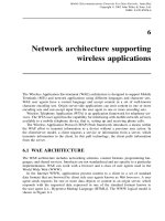
The application of DOT and MAT to the IN architecture provides benefits to the service
provisioning process as shown in Figure 2.1, with maintaining the basic principle of IN
related to call and service separation.
The introduction of DOT and MAT at the service design and deployment level allows
for r eusability for easy and rapid deployment of services, extensibility towards new and
updated services, a nd flexibility of service design. The adoption of DOT and MAT within
the Service Switching Points (SSPs) allows for services distribution among the switches
with faster handling of service requests, more reliable service execution, and network
scalability.
In the IN architecture, the control of the network resources is performed by the signaling
plane, whereas the service creation, deployment, and provisioning is performed by the
service plane. This separation allows introduction of new services and service features
Intrinsic
bottlenecks in
traditional IN
can lead to poor
performances
New technologies
for network
unaware of
distributed
applications
High expenses
in switching
design and
maintenance
Mobile code
supports
dynamically
reconfigurable
network structures
Adaptive broadband service provisioning architecture
Open switching platforms able to accommodate mobile code
Figure 2.1 Application of DOT and MAT to the IN.
AGENT-BASED SERVICE IMPLEMENTATION 13
without changing the basic functionality of the network for the establishment and the
release of resources such as calls and connections.
In the IN architecture, the intelligence is kept inside the core network that reduces
the need to update the equipment of the Access Network (AN) representing the most
widespread and expensive portion of the overall network. The IN architecture shown in
Figure 2.2 comprises functional e ntities mapped into physical elements.
The communication between network entities is done through Signaling System No. 7
(SS7). The Intelligent Network Application Protocol (INAP) also uses SS7 for the IN
SCS
SCEF
SMS
SMAF
SMF
SCP
SDF
SCF
SSP
SSF
CCF
IP
SRF
Physical entities
Functional entities
SCS
SMS
SCP
IP
Service
Creation System
Service
Management
System
Service
Control Point
Intelligent
Peripheral
SSP
Service
Switching Point
SSF
CCF
SDF
SCEF
SRF
SCF
SMF
SMAF
Service Switching
Function
Call Control
Function
Service Data
Function
Service Creation
Environment Function
Specialized Resource
Function
Service Control
Function
Service Management
Function
Service Management
Access Function
Figure 2.2 Deployment of functional entities to physical entities in the IN.
14 MOBILE AGENT-BASED SERVICE IMPLEMENTATION, MIDDLEWARE, AND CONFIGURATION
SMS
SCE
SSP
TE TE TE TE
SSP
MAP
1
3. . .
n
2
ORB
MAP
SCP SCP SCP
MAP MAP MAP
Signaling system #7
• • •
• • •
Figure 2.3 Introduction of DOT and MAT in the IN for service design, deployment, and
maintenance.
messages. IN architecture can support third-generation mobile systems and has the capacity
of the third-party call setup between IN and the Internet.
Figure 2.3 illustrates how DOT and MAT are introduced at the service design, deploy-
ment, and maintenance level. Services are designed as Java-based MAs in Service Creation
Environments (SCEs) and then transferred to the Service Control Points (SCPs) by using
capabilities provided by Mobile Agent Platforms (MAPs). In this architecture, SCPs
contain CORBA and MAT in their design. Service providers benefit from a flexible
service-provisioning environment by adopting object-oriented techniques for software
design and by using MAT facilities to apply immediate and sophisticated policies for
release distribution, update, and maintenance. Service Management System (SMS) stores
and distributes services and manages the running service instances.
MAPs are introduced in the switching nodes. CORBA method invocations are used
between SSPs and SCPs as an alternative to INAP as shown in Figure 2.4. The service
logic (arrow 1) can be duplicated and distributed to the SCPs (arrows 2, 3, n), and directly
to the SSPs. In this case, SS7 is only used for communication between SSPs.
This architecture with service distribution to the switches allows for faster handling of
service requests, higher reliability in handing the services, scalability, and reduction of
traffic in the signaling network.
Service requests are handled faster by using a n agent in the switch that causes call
handling, which usually does not require the establishment of a transaction with an SCP
and the consequent exchange of messages in the network. Therefore, no complex protocol
stacks are needed below the application part. Instead, c ommunication between internal
switch processes occurs.
AGENT-BASED SERVICE IMPLEMENTATION 15
SMS
SCE
MAP
1
3. . .
n
2
ORB
MAP
SCP SCP SCP
MAP MAP
TE TE
SSP
MAP
TE TE
SSP
MAP
MAP
Signaling system #7
• • •
Figure 2.4 Introduction of MAPs in the IN switches.
The impact of network f aults on the behavior of service is reduced since the network is
accessed mainly to download the service logic. Network errors can occur during download-
ing Service Location Protocols (SLPs) (i.e., agent migration) or during a Remote Method
Invocation (RMI) (through CORBA infrastructure). These situations can be handled by
using persistent mechanisms. Most MATs offer persistent agent facilities and, for CORBA
objects, the Persistent Object Service (POS) can be used. This way service performance
degradation is reduced.
The problem of having centralized points is solved by distributing the service code
across the network, which has a larger number of switches than SCPs. Dynamic SLP/SDT
(Service Description Table) distribution allows IN services to be spread across the network
to satisfy higher demand for those services. The distribution is performed dynamically
when it is needed. In a distributed IN, the SLPs of the first IN calls are downloaded from
the SMS to the SCP and then executed in the SCP. When the capacity of IN calls in
SCP is exceeded, the SLPs are downloaded to the SSP, which must have the processing
power and infrastructure to accomplish the new tasks (i.e., the SSP must also provide
SCP functionality). This way the SCP can accommodate a higher number of calls and
is restricted to the user interaction functionality [Broadband Special Resource Function
(B-SRF) capability]. The distribution of the SLP to the attached SSPs can sustain the
additional processing required per call.
Traffic in the signaling network is reduced by moving services closer to the cus-
tomers, and the messages related to servic e control are handled locally. The overhead of
downloading service programs is done off-line and does not impact signaling performance.
The distribution of services to the switches does not affect the IN basic principle of
distinguishing between enriched call control (Call Control/Service Switching Functions,
CCF/SSF) and service intelligence (Service Control Function, SCF). The detection of IN
call attempts is still determined at call control level, and following that, an invocation of
IN facilities is done by the switch. The difference is now in the communication technology
16 MOBILE AGENT-BASED SERVICE IMPLEMENTATION, MIDDLEWARE, AND CONFIGURATION
7
F
89
R
456
1
0
*
#
23
7
F
89
R
456
1
0
*
#
23
7
F
89
R
456
1
0
*
#
23
Agency
Agency
SCS
B-SCP
SEN
B-IP
SLP/
SDT
SMS
SCS
SMS
INAP
INAP
INAP
B-IP
B-SCP
B-SSP
Agency
Agency
Agency
INAP
INAP
B-SSP
B-SS&CP
INAP
End user
devices
IN
Agent-based IN
SLP/
SDT
Figure 2.5 Distributed IN architecture.
between SSF and SCF, which is based on CORBA principles. Backward compatibility
with traditional IN can be achieved by using IN/CORBA gateways, which allow for
gradual introduction of distributed IN as advanced service islands. The distributed IN
architecture is shown in Figure 2.5. In this figure, prefix B- is used with the IN functional
entities to indicate the application of IN concepts to a broadband environment.
Broadband infrastructure is not a mandatory requirement and the benefits of MAT/DOT
techniques to IN apply also to a narrowband architecture.
The following network elements are used in the network architecture: Service Creation
System (SCS), SMS, Service Execution Node (SEN), Broadband Service Switching and
Control Point (B-SS & CP), and Customer Premises Equipment. For broadband multime-
dia services, the terminals need to have support to access switched broadband network
(e.g., ATM). They need to have specialized hardware (e.g., ATM cards) and firmware (e.g.,
User to Network Interface – UNI signaling stack). MAT and CORBA can be applied to
network physical entities including terminals.
Services are developed and tested within SCE. The SMS provides service storage,
service uploading to network elements, and service control capabilities (i.e., agent local-
ization, alarm handling). The SEN is the physical element that joins the roles of the
Broadband Service Control Point and Broadband Intelligent Peripheral. Broadband SSP
AGENT-BASED MIDDLEWARE 17
has the capability to locally execute services downloaded from the network and is named
B-SS & CP.
In distributed IN where CORBA can be used for message exchange, generic program-
ming interfaces are available for developers. In this architecture, B-SCF, B-SDF, and
B-SRF are implemented as CORBA-based software components allowing DPE’s location
transparency and direct method invocation.
There are several benefits of distributed IN architecture. The network elements can
communicate in a homogeneous way. The SEN can be the contact point between the
users and the network. The operator can choose a distributed, centralized service or
mixed service.
Interactive Multimedia Retrieval (IMR) is an integrated multimedia service within the
framework of broadband IN. Broadband Video Telephone (BVT), is a real-time, multime-
dia, two-party service that provides two geographically separated users with the capability
of exchanging high-quality voice information, together with the transmission of high-
quality video data. BVT is offered by Broadband-Integrated Services Digital Network
(B-ISDN), which supports the facilities requested by the new generation of multimedia
workstations.
The BVT service uses mobility management procedures to enable users to register
at different (fixed) terminals. In a manner similar to the IMR and BVT services, the
realization of these procedures is based on DOT and MAT.
MAs enable both temporal distribution (i.e., distribution over time) and spatial dis-
tribution (i.e., distribution over different network nodes) of service logic. In multimedia
services, the porting of services usually occurs between IN elements of different types
(SSPs and SCPs), whereas in mobility services, the porting of services is usually between
modules of the same type (SCPs). These two approaches are not alternative and can be
combined; therefore, if multimedia services are offered to mobile users, then MAT can
be widespread in the IN architecture in the most effective way.
2.2 AGENT-BASED MIDDLEWARE
Terminal and user mobility are important aspects of communications systems. Laptop com-
puters, Personal Digital Assistants (PDAs), and mobile phones are the elements of mobile
office. The Agent-based Mobile Access to Multimedia Information Services (AMASE)
supports agent mobility.
A mobility system that can be accessed by a user from any kind of terminal must
have an appropriate device support and must be scalable, that is, the mobility system can
be installed on different kinds of devices, especially mobile devices with strict resource
constraints such as PDAs and mobile phones. A mobility system can be sized from a
full-fledged system to a subsystem until it reaches a size and complexity that matches the
constraints set by the devices involved and still provides all the required services.
The distributed AMASE Agent Environment comprises several devices and nodes,
each running one instance of the stand-alone AMASE Agent Platform, which can be
scaled to fit into different device types. The agent system shown in Figure 2.6 consists
of two layers, the Agents System (AS) and the communication facilities. Communication
18 MOBILE AGENT-BASED SERVICE IMPLEMENTATION, MIDDLEWARE, AND CONFIGURATION
Administration API CF APIAgent API
CF API
AMASE
Agent system
Persistent
storage
Agent manager
Communication manager
Monitoring
module
User
manager
Fixed networks Cellular networks Wireless LANs
Communication Facility (CF)
Security
manager
Resource
manager
Agent soft-
ware update
System
state
Configu-
ration
Agent
state
Mobile and system
agent handling
Unique naming
module
Event
handling
Service trading Service center Remote service call
CF-service
handler
Agent
communication
protocol handler
Agent
transport
protocol handler
Agent
directory
protocol handler
Figure 2.6 Architecture of the AMASE system.
facilities provide access to a broad range of underlying networks and handle the roaming
between different kinds of networks.
The AS layer provides a runtime environment for cooperative MAs. This layer allows
agents to migrate from one AS to another, to access services available in the network,
and to communicate with other agents. The Service Center of the Agent System is a
fundamental component for mobile agent management and user mobility and is used for
locating and accessing services and agents.
The AMASE system and its supported agents are developed in Java. An agent system
launcher supports loading a scaled version of the AS into a mobile device and executing
it on different Java Virtual Machines (JVM). The launcher closely cooperates with a unit
for agent system software update allowing for upgrading the AS’s software at least at
start-up or upon request. An agent launcher is used for application allowing for more
convenient and browser-like launching of agent-based applications by hiding all the Java
and agent system specifics.
The core of the AS is the Agent Manager (AM), allowing MAs access to the application-
specific parts of the AS’s functionality via an agent API. The communication facilities
are interfaced by AS’s Communication Manager (CM), and the communication facilities
detect connection to available networks and their special services. The CM establishes
the protocols for interagent communication, agent migration, and for accessing a Service
Center and its Agent Directory (AD) via its protocol handlers.
AGENT-BASED MIDDLEWARE 19
The Persistent Storage area is either located in the persistent memory area of the
underlying device, or on a magnetic medium. This area is needed to save agents and the
agent system state and configuration.
The C M comprises user and security managers that establish a user management and
allow for the enforcement of access policies. An additional resource manager provides
information about device utilization, for example, memory or agent population. A com-
ponent for dynamic updates of the agents’ software allows for versioning and updates of
agent classes.
The AM is responsible for controlling the agent population of the agent system. AM
allows for launching and termination of agents and provides them with the functionality
needed for migration, communication, service access, and so on. In AMASE environment,
there are MAs and system agents. MAs are c reated by application and they can roam
within the network. They are not allowed to access system resources for security reasons.
Usually these agents interact with the user for an initial configuration before they are
launched into the network. They allow the user to perform remote operations without a
constant network connection.
MAs and system agents are supported by the AS. System agents can access system
resources and become a mediator between the MAs and the system resources and the
services they need to access.
The AM cooperates with the user manager and the resource manager, which permits
them to assign detailed access rights to agents. Both agent types are maintained separately
by the AM, which supports a clearly defined type-dependent handling, for example, in case
of a shutdown. Agents are registered with the local AM, and MAs are also automatically
registered with the Service Center’s AD.
In Figure 2.6, the CM connects the entire agent system to the communication facilities,
which c onnect a device to the available networks. The CM surveys preconfigured ports on
sockets provided by the communication facilities to receive incoming messages. Agents
can be dispatched and handled by the AM. Each CM has access either to a local or
remote router provided by the agent-related directories. This router helps CM to find and
address the other agent systems. The CM is responsible for converting Java objects into
byte streams and is involved in synchronous communication, which requires temporal
suspension of agents.
CM and communication facilities optimize communication and connection handling.
The protocols consider network and device characteristics, and Quality of Service (QoS)
information. Connections are physically closed during timeouts but kept open virtually.
These operations that are transparent to the agents save connection costs and support
disconnected operations and user mobility. The following communications mechanisms
are provided by using the agent system communication manager, its protocol handlers,
and the underlying communication facilities:
• asynchronous one-way agent-to-agent messages;
• synchronous two-way agent-to-agent messages based on Remote Procedure Call
mechanisms;
20 MOBILE AGENT-BASED SERVICE IMPLEMENTATION, MIDDLEWARE, AND CONFIGURATION
• blackboards for local agent communication within agent systems – a blackboard is a
data area where agents can leave information that may be read and removed by other
agents under configurable access restrictions;
• postbox messages for specified agents; this is a message queue that belongs to a
single agent and which is located at a well-known location in the network that is
known to both the message senders and the postbox owner; the owner agent can
only read the box contents and remove the messages, and all other agents can drop
messages.
MAs are capable of migrating, which can occur at any time; thus, a mechanism is
needed to determine an agent’s current location. This mechanism is not necessary for
asynchronous communication and communication based on blackboards and postboxes; it
is inevitable for direct communication of agents. The Mobile Agent System Interoperabil-
ity Facility (MASIF) specifies a Mobile Agent Facility (MAF) component MAFFinder,
which is an abstract facility for mobile agent localization. MAFFinder is abstract because
it does not specify how the agents are to be localized – only that a presence of such
facility is required. Concepts for mobile agent localization include broadcast, forwarding,
and directory service/home registry.
AMASE system introduces a Service Center based on a directory service using general
mobile agent execution cycle. MAs are restricted in their size and complexity owing to
the costs of agent migration. MAs use services to execute the tasks required. The agents
contact a facility in the agent system that provides a naming or trading service and passes
information on the location of the requested services. This Service Center in AMASE
system is based on the concept introduced by the Java Agent Environment (JAE).
AMASE system introduces a ticket concept to pass information to MAs while keeping
the actual migration and location information transparent. Mobile agent r equesting a
service from the Service Center receives a ticket shown in Figure 2.7. By calling useSer-
vice (ticket), the MA uses the service provided, migrating to the respective agent system if
it is not located in the same agent system. In addition to the information a bout home loca-
tion, destination, and migration history, it is possible to store additional data in the ticket
object, for instance, departure time, maximum number of connection retries, and priority
information. The origin entry provides details about the creation and the starting point of
the MA that is needed if the agent returns after having accomplished its task. Because of
the user mobility and the disconnected operations, the originating device might be turned
off and may become unreachable for the mobile agent. In this case, the permanent home
entry gives an alternative address. The permanent home is an agent system at the service
provider or the agent enabled home computer.
The architecture of the Service Center shown in Figure 2.8 introduces a new mechanism
for localizing MAs by using the AD. Whenever a MA requests a new service or migrates
to another host, its position is updated in the Service Center. The agent location is stored
in the AD. This is implemented as a Lightweight Directory Access Protocol (LDAP)
server, with the Service Center holding an LDAP client for accessing the AD.
In this approach, a MA’s position is always known by the Service Center. The update
of the agent’s position is embedded in the agent migration process; a migration is not
completed before the update has been executed. This way the MAs can always be tracked.
AGENT-BASED MIDDLEWARE 21
Destination:
Departure:
Departure Time:
Origin:
Permanent Home:
History:
amase.rwth.as4
amase.rwth.as3
30 min
amase.rwth.as_mobile0
amase.rwth.as0
amase.rwth.as3
amase.rwth.as1
amase.rwth.mobile0
Properties: IDENTITY
Property 1 UserID
RetryDelay System
MaxRetry
8
100 ms
20 Domain
TICKET
Figure 2.7 An abstract ticket object.
LDAP AD
Other
service centers
LDAP
client
Trader
Service center
SC
management
and remote
service
call
Local
services
Mobile
agents
SC − API
Figure 2.8 Architecture of the service center.
There are no message bursts caused by agent localization. The AD concept allows a seam-
less integration into the facilities required for localization services for mobile agent use.
The AMASE system allows the user to access individually configured services and
data from different kinds of terminals, keeping transparent the details of the configuration
and underlying mechanisms. The user profiles a re in the profile directory similar to the
22 MOBILE AGENT-BASED SERVICE IMPLEMENTATION, MIDDLEWARE, AND CONFIGURATION
AD. A user profile contains information about the user’s preferences and data, display and
security settings, and scheduling information and address books. The profile directory is
a generic database for maintaining user information, which includes application-specific
data. Customized agents adapted to application-specific needs can be created on the device
the user is currently deploying. The user can specify types of services to be used without
having to be aware of their location or current availability.
The mobility middleware system is presented in Figure 2.9. The mobile agent, equipped
with the service description and a specification of the preferred mechanism to return
results, contacts the AD to localize the appropriate system agents that provide the required
services. The agent obtains the ticket and migrates to the appropriate system agents and
uses their services. Once the results are generated, the profile directory is used. If the user
specified a type of terminal to deliver the results, the MA obtains the address from the
profile directory and returns the results via the respective telecommunication service. On
the other hand, if the user does not specify a method for returning the results, the MA
decides which method to use. User and terminal profiles used with MAT create a flexible
and device-independent user mobility.
The users can become temporarily unreachable when the results are available. MAs
allow the users to disconnect after specifying the service. If the method specified for
returning the result is an asynchronous message (e.g., e-mail, fax), no feedback is required
by the MAs. On the other hand, if the agent’s execution depends on the user’s feedback
or if the return method is selected by the user after an initial notification, the MA can-
not be terminated and must wait for user input to continue execution. The AMASE
system introduces the kindergarten concept for an MA, which recognized that the tar-
get user is currently unavailable, or, if the execution of the notification method failed
Service center
(agent directory)
Service center
(profile directory)
Telecommunication
services
Mobile agent-
kindergarten
Mobility middleware
(Fixed network) agent system
System agents
Contact user
(Mobile)
agent system
3
6
5
4
2
1
Figure 2.9 The agent-based mobility middleware.
MOBILE AGENT-BASED SERVICE CONFIGURATION 23
2
Storage
Coordinator
Persistent
storage
Mobile agent kindergarten
1
Figure 2.10 The mobile agent kindergarten concept.
or timed out, to contact a kindergarten coordinator that checks if the system having
last served the MA is capable of holding this agent until the user becomes available.
In this case, the agent is suspended until further notice. The agent is instructed to
migrate to a host providing a kindergarten storage. This server suspends the MA and
resumes it when the user reconnects. The MA can also be moved to persistent stor-
age until being resumed, which allows for managing a large number of MAs. The
kindergarten concept shown in Figure 2.10 provides a mechanism for handling MAs
belonging to disconnected users and forms the basis of mobility support deploying user
and terminal profiles.
2.3 MOBILE AGENT-BASED SERVICE
CONFIGURATION
MAT allows for object migration a nd supports Virtual Home Environment (VHE) in
the Universal Mobile Telecommunications System (UMTS). VHE uses MAs in service
subscription and configuration.
UMTS supports QoS, the Personal Communication Support (PCS), and VHE. The
VHE allows for service mobility and roaming for the user, which carries subscribed and
customized services while roaming. During the registration procedure, the VHE enables
the visited network to obtain the information about the user’s service provider, the user’s
personalized service profile, and the identification about service capabilities to execute
specific services.
The VHE architecture shown in Figure 2.11 can be viewed as middleware layer that
hides from the user the concrete network capabilities and differences in user and provider
system capabilities. Service intelligence can be located inside the network within the
Service Control and Mobility Management Platform (SC & MMP) or outside the network
within the Universal Service Identification Module (USIM) of the end system. Service
adaptation and media conversion is needed to cope with the diversity of end systems
supporting personal mobility and QoS variations of different ANs supporting terminal
24 MOBILE AGENT-BASED SERVICE IMPLEMENTATION, MIDDLEWARE, AND CONFIGURATION
Provider
systems
End
systems
Applications (subscribed services)
Virtual home environment
Transport networks
Figure 2.11 Virtual home environment.
mobility. The enhancements of service control intelligence during service execution and
dynamic subscription of a new third-party services should be allowed in the system.
The UMTS environment shown in Figure 2.12 consists of a terminal, the AN, the
SC & MMP, and the third-party service provider. A user registers at the terminal that
presents services to the user. The user’s identification and authentication is handled by
the UMTS Subscriber Identity Module (USIM). The network access of the terminal is
managed by the access network. Fixed or mobile terminals are linked by the AN to the
SC & MMP. The SC & MMP contains service logic and is responsible for the mobility
management. Third-party service provides support supplementary services. A third-party
service provider has a connection to one or more SC & MMPs and does not have its own
mobility management facilities.
A middleware layer is introduced in UMTS architecture in Figure 2.13. The middleware
consists of Distributed Agent Environment (DAE), for example, Grasshopper, which is
built on the top of DPE, for example, CORBA, and spans all potential end user systems
and provider systems. The nodes provide agent environments through middleware system
SC&MMP
SC&MMP
ANAN
Mobile station
USIM
SC&MMP
Third party SP
Third party SP
Third party SP
End user system Home provider system Other provider system Third party provider system
Figure 2.12 The main components of the third-generation mobile communication system.
MOBILE AGENT-BASED SERVICE CONFIGURATION 25
AN
Mobile station
USIM
Visited MSC Gateway MSC Third party service provider
AgencyAgencyAgency
Agents
DPE/DAE
Core
network
Agency
Figure 2.13 The d istributed agent environment spanning across UMTS end user and
provider systems.
to enable downloading and migration of MAs. MAs contain intelligence related to mobility
management and service control (VHE control) and the end user application between the
involved system nodes, including the Mobile Stations (MSs).
In agent-based UMTS, a VHE-agent realizes the VHE concept; a Service Agent (SA)
represents a provided service; a Terminal Agent (TA) allows the terminal to inform the
provider system about its capabilities; and a Provider Agent (PA) realizes a trader within
the provider system, which manages all supported services (SA), that is, maintains an
overview of all available services within the provider domain.
The VHE allows individually subscribed and customized services to follow their associ-
ated users wherever they roam. The VHE-agent follows the user to the domain to which
the user is roaming. At every domain, the VHE-agent provides the user’s subscribed
services and configurations.
Agencies in the MS allow dynamic distribution of mobility management and service
control intelligence to be downloaded dynamically from the MS into the (visited) provider
system and from the (visited) provider system onto the MS, to be distributed within one
provider system at the most appropriate location and to be distributed between different
provider systems. The end systems through the USIM can take an active part in mobility
management and service control.
The PA residing in every provider domain contains the knowledge of all services
provided by this domain. The PA is designed as a trader in MASIF. The PA is the
initial contact point of the VHE-agent after the user is roamed to a new domain. The
PA is designated as a stationary agent since its task makes the migration of this agent
not necessary.
The SAs are located within the provider domain, or at the third-party service provider
domains, or at the user’s terminal. The Converter Agents (CAs) at the provider agency are
responsible for converting incoming and outgoing calls on the basis of user and terminal
requirements. This allows for support of services on terminals that cannot originally
26 MOBILE AGENT-BASED SERVICE IMPLEMENTATION, MIDDLEWARE, AND CONFIGURATION
USIM agency
Service agents
Service provider agency
Third party service agents
Converter agents
SA
SA
SA
PA
VHE
TA
Outgoing
(access)
Incoming
Figure 2.14 Basic agent relationships.
present the service such as reading out a fax or e-mail on a telephone. The knowledge
of the terminal capabilities is maintained by the TA. Different types of agents and their
communication relationships are shown in Figure 2.14.
The VHE-agent can migrate from the provider domain from which the user comes to
the provider domain to which the user is roaming. Another possibility is to store a major
copy of the VHE-agent within the home service provider domain. Whenever the user
roams to a new provider domain, a copy of the VHE-agent migrates to this domain. The
VHE-agent can also be stored on the terminal agency. The VHE-agent migrates from the
terminal agency to the provider agency when the user roams to a new domain.
Dynamic subscription allows a user to subscribe to and to unsubscribe services. The
subscription component presents the entire set of provided services to the user. The
information can be retrieved during the registration procedure after the user roamed to a
new provider, and the subscription component requests the provider to get information
about provided services. The services of a new provider can also be concatenated to the
service list that is stored by the VHE. The network can provide a roaming broker that can
be contacted by the subscription component to get the information about service providers.
The abstract service subscription is present at the provider where the user r oams.
The user registers at the new provider, and the VHE-agent contacts the PA to receive a
subscription interface to process the VHE request. The PA finds an SA that corresponds
to the abstract service description. The PA returns a reference to the existing SA that
matches with the service description. If there is no SA matching service description, the
PA finds a corresponding agent at different service providers. The PA explores possibilities
illustrated in Figure 2.15. The current service provider can contact other service providers,
or a roaming broker can be used, or the home service provider can provide a reference
to the service agent.
The User Interface Agent (UIA) is responsible for the presentation of the SA at
the user’s terminal. The UIA provides terminal-dependent service presentation capabil-
ities. The same service can be represented by many UIAs for terminals with different
capabilities. The VHE-agent decides which UIA download to the terminal as shown in
Figure 2.16. The VHE-agent contacts the TA, which resides on the terminal agency, that
MOBILE AGENT-BASED SERVICE CONFIGURATION 27
Third party service provider region
Third party SP agency
Roaming Broker Agency
Place
SA
PA
RBA
2
2
3
2
PA
TA
VHE
SA
SA
Place Place
MSC agency
USIM agency
Mobile station
1
1
1 - Provider agent tries to find a service
agent in its own domain and with capabilities
that can be presented at the terminal of
the user
2 - Provider agent contacts the Roaming
Broker (RB). The RB tries to find a matching
service agent
3 - Provider agent contacts the home
service provider to get access to the
service agent
Home service provider region
Visited service provider region
PA
Place Place
Home service provider agency
SA
SA
Figure 2.15 Service access strategies.
1
4
2
3
Service provider region
TA
Place
SA
PA
VHE
Place
MSC agency
USIM agency
Mobile station
1- VHE-agent requests the Terminal Agent to
get properties of the terminal. This information
will be sent by the TA to the VHE-agent.
2 - The VHE-agent will request the provider
agent.
3 - To find a corresponding UIA.
4 - If a UIA was found, it will be downloaded to
the terminal agency.
Figure 2.16 The UIA selection procedure.
28 MOBILE AGENT-BASED SERVICE IMPLEMENTATION, MIDDLEWARE, AND CONFIGURATION
is, mobile station. This TA is device dependent and contains technical information about
the terminal. The VHE-agent requests the TA to get this information. The returned val-
ues are used by the VHE-agent to find a corresponding UIA. The service subscription
procedure is used to locate the UIA.
2.4 MOBILE AGENT IMPLEMENTATION
MAs can be implemented in Java programming language. Additional features and mech-
anisms supported and envisioned in Jini programming language allow for implementation
of mobile devices in practical systems.
The Jini vision introduced by Edwards allows for devices and software services to work
together in a simple, fast, and reliable manner. The requirements for devices a nd software
specify robust software infrastructure developed to support reliable systems. The devices
must be easy to use and administer, and should work instantly after being connected. The
software systems must be evolvable, and software services and devices should permit their
use without reconfiguration of the network. These devices form spontaneous communities
within dynamic networking.
Mobile code is used in several structures to support mobile applications. In Java pro-
gramming language, applets are used for small applications to be installed automatically
wherever they are needed and removed when their users do not need them. In the agent
paradigm, small, autonomous bits of code travel to search for desired data. The mobile
code is used for performance and autonomy. Agents can provide a better performance
as the code moves closer to data in the network. Agent autonomy allows the user to
log off or shut down the machine, and the agent that left the originator computer can
continue to run even if the originator disconnects. Java RMI allows for building various
distributed systems and can be used for automatic application installation or for building
agent-based systems. Mobile code in RMI is used for object-oriented networked systems
and it supports evolvable implementations of remote objects and new implementations of
parameter and return types. Jini uses mobile code to achieve maintenance, evolvability,
and ease of administration for networked devices and services. Jini is layered atop RMI,
allowing all the benefits of mobile code to be used by programs in Jini.
Jini supports spontaneously created self-healing communities of services, and it is
based on the concepts of discovery, lookup, leasing, remote events, and transactions.
Jini uses discovery protocols to find the available lookup services. The Multicast
Request Protocol is used to find the active lookup services after an application or service
becomes initiated. Lookup services announce their existence in the system by using the
Multicast Announcement Protocol. An application or service talks to the lookup service
by using the Unicast Discovery Protocol.
The lookup service is a process that has semantic information about available services.
The service items have proxy objects and attributes describing these services.
Jini concept of leasing allows the resource to be loaned to a customer for a fixed period
of time rather than granting access to a resource for an unlimited amount of time. This
ensures that the communities of services are stable, self-healing, and resilient to failures,
errors, and crashes.
PROBLEMS TO CHAPTER 2 29
Jini uses remote events to allow services to notify each other about the changes in
their state. These are messages sent as asynchronous notifications directly to a software
component and handled outside the normal flow of control of the component.
Computations involving multiple services reach safe and known state by using transac-
tions in Jini. Transactions provide atomicity, consistency, isolation, and durability to data
manipulations. All the operations under transactions are executed as a n atomic operation.
Transactions ensure state consistency after completion. Transactions are isolated during
execution; they do not affect one another until completion. Transaction durability makes
the changes permanent.
2.5 SUMMARY
MAT uses the capabilities provided by machine-independent, interpreted languages like Java
to deploy a framework in which applications can roam between network nodes maintaining
their execution status. MAT platforms are often based on a CORBA DPE layer, which allows
distributed applications to dynamically reconfigure their layout according, for instance, to
processing needs. This way certain MAs may have a CORBA interface enabling them to
exploit the facilities offered by the distributed objects communication infrastructure.
The introduction of DOT and MAT at the service design and deployment level allows
for reusability for easy and rapid deployment of services, extensibility towards new and
updated services, and flexibility of service design.
The AS layer provides a runtime environment for cooperative MAs. This layer allows
agents to migrate from one AS to another, to access services available in the network, and
to communicate with other agents. The Service Center of Agent System is a fundamental
component for mobile agent management and user mobility and is used for locating and
accessing services and agents.
MAT allows for object migration and supports VHE in the UMTS. VHE uses MAs in
service subscription and configuration.
The UMTS environment consists of a terminal, the AN, the SC & MMP, and the
third-party service provider.
In agent-based UMTS, a VHE-agent realizes the VHE concept; an SA represents a pro-
vided service; a TA allows the terminal to inform the provider system about its capabilities;
and a PA realizes a trader within the provider system, which manages all supported services
(SA), that is, maintains an overview of all available services within the provider domain.
PROBLEMS TO CHAPTER 2
Mobile agent-based service implementation, middleware, and configuration
Learning objectives
After completing this chapter, you are able to
• demonstrate an understanding of distributed object technology;
• discuss what is meant by intelligent agents;
30 MOBILE AGENT-BASED SERVICE IMPLEMENTATION, MIDDLEWARE, AND CONFIGURATION
• demonstrate an understanding of agent-based service implementation;
• explain how to handle service requests;
• explain temporal and spatial distribution of service logic;
• discuss multimedia services;
• demonstrate an understanding of a mobility system;
• explain what agent system, agent manager, and communication manager are;
• explain mobility middleware system;
• demonstrate an understanding of the Universal Mobile Telecommunications System
(UMTS);
• discuss what an agent-based UMTS is;
• demonstrate an understanding of the VHE concept;
• explain how the VHE-agent migrates in the system;
• explain dynamic subscription of services;
• demonstrate an understanding of mobile agent implementation in Java program-
ming language;
• demonstrate an understanding of mobile agent implementation in Jini program-
ming language.
Practice problems
2.1: What is the role of DPE in DOT?
2.2: What are the functions of Intelligent and Mobile Agents?
2.3: What distribution of service logic is enabled by Mobile Agents?
2.4: What are the requirements for a mobility system?
2.5: What is the role of the Agent System layer?
2.6: Where is the Persistent Storage located and why is it needed?
2.7: What is supported by the UMTS?
2.8: What are the elements of the UMTS environment?
2.9: How is the VHE concept realized in agent-based UMTS?
2.10: What is the role of dynamic subscription?
2.11: What is the role of the User Interface Agent (UIA)?
2.12: What are applets used for in Java programming language?
2.13: What is the concept of Jini programming language?
Practice solutions
2.1: DOT provides a DPE to enable designers to create object-oriented distributed appli-
cations, which are not necessarily aware of the physical layout of the underlying
network structure hidden by platform services.
2.2: Intelligent Agents have the ability to learn and react. MAs can migrate between
different hosts, execute certain tasks, and collaborate with other agents.
2.3: MAs enable both temporal distribution (i.e., distribution over time) and spatial
distribution (i.e., distribution over different network nodes) of service logic.
2.4: Mobility system that can be accessed by a user from any kind of terminal must
have an appropriate device support and must be scalable, that is, the mobility system
PROBLEMS TO CHAPTER 2 31
can be installed on different kinds of devices, especially mobile devices with strict
resource constraints such as P DAs and mobile phones. A mobility system can be
sized from a full-fledged system to a subsystem until it reaches a size and complexity
that matches the constraints set by the devices involved and still provides all the
required services.
2.5: The AS layer provides a runtime environment for cooperative MAs. This layer
allows agents to migrate from one AS to another, to access services available in
the network, and to communicate with other agents. The Service Center of AS is a
fundamental component for mobile agent management and user mobility, and it is
used for locating and accessing services and agents.
2.6: The Persistent Storage area is either located in the persistent memory area of the
underlying device or on a magnetic medium. This area is needed to save agents
and the agent system state and configuration.
2.7: UMTS supports QoS, the PCS, and VHE.
2.8: The UMTS environment consists of a terminal, the AN, the SC & MMP, and the
third-party service provider.
2.9: In agent-based UMTS, a VHE-agent realizes the VHE concept; an SA represents a
provided service; a TA allows the terminal to inform the provider system about its
capabilities; and a PA realizes a trader within the provider system, which manages
all supported services (SA), that is, maintains an overview of all available services
within the provider domain.
2.10: Dynamic subscription allows a user to subscribe to and to unsubscribe services.
The subscription component presents the entire set of provided services to the user.
2.11: The UIA is responsible for the presentation of the SA at the user’s terminal. The
UIA provides terminal-dependent service presentation capabilities. The same service
can be represented by many UIAs for terminals with different capabilities.
2.12: In Java programming language, applets are used for small applications to be installed
automatically wherever they are needed, and removed when their users do not
need them.
2.13: Jini supports spontaneously created self-healing communities of services and is
based on the concepts of discovery, lookup, leasing, remote events, and transactions.