Tài liệu Điện thoại di động giao thức viễn thông cho các mạng dữ liệu P3 ppt
Bạn đang xem bản rút gọn của tài liệu. Xem và tải ngay bản đầy đủ của tài liệu tại đây (164.22 KB, 21 trang )
3
Wireless local area networks
Virtual LANs provide support for workgroups that share the same servers and other
resources over the network. A flexible broadcast scope for workgroups is based on
Layer 3 (network). This solution uses multicast addressing, mobility support, and the
Dynamic Host Configuration Protocol (DHCP) for the IP. The hosts in the network are
connected to routers via point-to-point connections. The features used are included in
the IPv6 (Internet Protocol version 6) protocol stacks. Security can be achieved by using
authentication and encryption mechanisms for the IP. Flexible broadcast can be achieved
through enhancements to the IPv6 protocol stack and a DHCP extension for workgroups.
Orthogonal Frequency Division Multiplex (OFDM) is based on a mathematical concept
called Fast Fourier Transform (FFT), which allows individual channels to maintain their
orthogonality or distance to adjacent channels. This technique allows data symbols to
be reliably extracted and multiple subchannels to overlap in the frequency domain for
increased spectral efficiency. The IEEE 802.11 standards group chose OFDM modulation
for wireless LANs operating at bit rates up to 54 Mb s
−1
at 5 GHz.
Wideband Code Division Multiple Access (WCDMA) uses 5 MHz channels and sup-
ports circuit and packet data access at 384 kb s
−1
nominal data rates for macrocellular wire-
less access. WCDMA provides simultaneous voice and data services. WCDMA is the radio
interface technology for Universal Mobile Telecommunications System (UMTS) networks.
Dynamic Packet Assignment (DPA) is based on properties of an OFDM physical layer.
DPA reassigns transmission resources on a packet-by-packet basis using high-speed receiver
measurements. OFDM has orthogonal subchannels well defined in time–frequency grids,
and has the ability to rapidly measure interference or path loss parameters in parallel on all
candidate channels, either directly or on the basis of pilot tones.
3.1 VIRTUAL LANs
Virtual LANs provide support for workgroups. A LAN consists of one or more LAN
segments, and hosts on the same LAN segment can communicate directly through Layer 2
(link layer) without a router between them. These hosts share the same Layer 3 (network
Mobile Telecommunications Protocols For Data Networks. Anna Ha
´
c
Copyright
¶ 2003 John Wiley & Sons, Ltd.
ISBN: 0-470-85056-6
34 WIRELESS LOCAL AREA NETWORKS
layer) subnet address, and communication between the hosts of one LAN segment remains
in this segment. Thus Layer 3 (network layer) subnet address forms a broadcast scope
that contains all hosts on the LAN segment.
The workgroups are groups of hosts sharing the same servers and other resources
over the network. The hosts of a workgroup are attached to the same LAN segment, and
broadcasting can be used for server detection, name resolution, and name reservation.
In a traditional LAN the broadcast scope is limited to one LAN segment. Switched LANs
use a switch infrastructure to connect several LAN segments over high-speed backbones.
Switched LANs share the Layer 3 (network layer) subnet address, but offer an increased
performance compared to traditional LANs, since not all hosts of a switched LAN have to
share the bandwidth of the same LAN segment. LAN segments connected over backbones
allow for distribution of hosts over larger areas than that covered by a single LAN segment.
Traditional switched LANs require a separate switch infrastructure for each workgroup
in the environment with several different workgroups using different LAN segments.
Virtual LANs are switched LANs using software configurable switch infrastructure. This
allows for creating several different broadcast scopes over the same switch infrastructure
and for easily changing the workgroup membership of individual LAN segments.
The disadvantage of virtual LANs is that a switch infrastructure is needed and admin-
istration includes Layers 2 and 3 (link and network). A desirable solution involves only
Layer 3 (network) and does not require special hardware.
Kurz et al. propose a flexible broadcast scope for workgroups based on Layer 3 (net-
work). This solution uses multicast addressing, mobility support, and the DHCP for the
IP. The hosts in the network are connected to routers via point-to-point connections. The
features used are included in the IPv6 protocol stacks. Security can be achieved by using
authentication and encryption mechanisms for the IP. Flexible broadcast can be achieved
through enhancements to the IPv6 protocol stack and a DHCP extension for workgroups.
In IPv6, a special address range is reserved for multicast addresses for each scope, and
a multicast is received only by those hosts in this scope that are configured to listen to
this specific multicast address. To address all hosts in a certain scope with a multicast, the
multicast must be made to the predefined all-nodes address, to which all hosts must listen.
When existing software using IPv4 (Internet Protocol version 4) is migrated to IPv6, the
IPv4 broadcasts are changed to multicasts to the all-nodes address, as this is the simplest
way to maintain the complete functionality of the software.
IPv6 multicasting can be used to form the broadcast scope of a workgroup. The
workgroup is the multicast group, whose hosts listen to the same multicast address, the
workgroup address. A host can listen to several multicast addresses at the same time and
can be a member of several workgroups.
Multicasting exists optionally for IPv4 and is limited by a maximum of hops. The
multicast in IPv6 is limited by its scope, which is the address range.
In a virtual LAN, the workgroup membership of a host is determined by configuration
of the switches. Kurz et al. propose that a host has to determine its workgroups and
their corresponding multicast addresses. Different workgroups are separated in Layer 3
(network) since each host has the possibility to address a specified subset of hosts of the
network using multicasting. All hosts can be connected directly to the routers, and the
members of different workgroups can share the same LAN segment.
VIRTUAL LANs 35
The administration of the workgroups is designed by storing the information about
hosts and their workgroups in a central database in a DHCP server. The information is
distributed by using the Dynamic Host Configuration Protocol version 6 (DHCPv6).
3.1.1 Workgroup management
In a workgroup address configuration, the host sends a DHCP Request with a Workgroup
Address Extension to the DHCP Server. The DHCP Server replies with a Workgroup
Address Extension containing all workgroup addresses assigned to this host. After receiv-
ing the workgroup addresses, the host sends the Internet Control Message Protocol
version 6 (ICMPv6) Group Membership Report to each of its workgroup addresses to
inform the multicast routers about its new membership in these multicast groups.
After learning its workgroup addresses, the host has to configure its interfaces to listen
to these multicast addresses. The host has to change all outgoing multicasts to the all-
nodes address (which are equivalent to IPv4 broadcasts) to multicast to the workgroup
address of the host. This can be done by changing the IPv6 stack to intercept all outgoing
multicasts to the all-nodes address and to change this address to the workgroup addresses
of the host. If the host is a member of several workgroups, the multicast has to be sent
to all workgroup addresses of the host.
The purpose of DHCP is to provide hosts with addresses and other configuration
information. DHCP delivers the configuration data in extensions that are embedded in
request, reply, or reconfigure messages. The request message is used by the client to
request configuration data from the server, and the reply message is used by the server to
return the requested information to the client. If there is a change in the DHCP database,
the server uses the reconfigure message to notify the client about the change and to start
the new request reply cycle.
Kurz et al. introduce a DHCP Workgroup Address Extension to deliver workgroup
addresses to the host. In a DHCP Request the client must set the workgroup count to zero,
must not specify any workgroup addresse s, and must specify its node name. In a DHCP
Reply the server must set the workgroup count to the number of workgroup addresses
existing for this client, include all workgroup addresses existing for this client, and use
the client’s node name. In a DHCP Reconfigure the server must set the workgroup count
to zero, must not specify any workgroup addresses, and must use the client’s node name.
Mobile hosts can be the members of workgroups. The Internet draft Mobility Support
in IPv6 proposes that a mobile host attached to a network segment other than its home
segment continues to keep its home address on the home segment and forms a global
care-of address for its new location. The binding update options included in IPv6 packets
are used to inform correspondent hosts as well as the home agent, a router that is on the
same segment as the home address of the mobile host, about its new care-of address. After
the home agent is informed about the new care-of address of the mobile host, the home
agent receives packets on the home segment addressed to the mobile host and tunnels
them to the care-of address of the mobile host.
Kurz et al. propose enhancements to the Internet draft Mobility Support in IPv6 for a
mobile workgroup member to send or receive multicast packets from its home network
and to participate in the multicast traffic of its group. If a mobile host leaves the scope
36 WIRELESS LOCAL AREA NETWORKS
of a multicast group it joined, the home agent must forward packets sent to the home
address of the mobile host and also all packets sent to the concerned multicast address.
The mobile host has to be able to send packets to the multicast address of its workgroup,
even though it is outside the scope of this address. This can only be done by tunneling
the packets to a host inside the scope of the multicast address and resending them from
that host. Since the home agent is on the segment associated with the home address of
the mobile host, the task of resending multicasts of a mobile host can also be taken over
by the home agent.
The Internet draft Mobility Support in IPv6 proposes a binding update option, which
is used to notify the home agent and other hosts about a new care-of address of a mobile
host. The original home link local address of the mobile host has to be specified in the
source address field in the IP header of the packet containing the binding update option.
It can also be specified in the home link local address field in the binding update option,
but a multicast address cannot be specified this way. Kurz et al. introduce an optional
field for a multicast address in the binding update option to inform the home agent about
workgroup addresses to which the mobile host listens. A field for the workgroup address
is used to indicate that there is a multicast group address specified in the option.
3.1.2 Multicast groups
A mobile host that left the scope of one of its multicast groups sends a binding update
option to its home agent to inform it about the new care-of address. A mobile host has
to specify its multicast group address in the binding update option. If the mobile host is
a member of several multicast groups, it has to send a binding update option for each of
its multicast groups.
A home agent notified by a binding update option about a multicast address for a
mobile host must join this multicast group and handle packets with this multicast address
in the destination address field in the same way as the packets with the home address
of the mobile node in this field. The mobile host must treat a received encapsulated
multicast packet in the same way as the packet received directly. The mobile host must
not send a binding update option to the address specified in the source address field of
an encapsulated multicast packet.
When sending a multicast packet to its multicast group, the mobile host has to use its
home address in the source address field of the multicast packet and tunnel this packet to
its home agent. When a home agent receives an encapsulated multicast packet in which
the source address field is the same as the home address of a mobile host served by it,
the home agent has to act like a router, receiving this multicast packet from the home
segment of the mobile host and additionally forwarding it to the home segment of the
mobile host.
This way of providing mobile workgroup members with the possibility to leave the
scope of the multicast address has a drawback that it may not scale well in the case of
broadcast intensive workgroup protocol stacks, since all the broadcasting traffic, which
was intended to remain in the limited area, has to be forwarded to the mobile node.
If many workgroup members use the possibility of global mobility, there is a risk of
overloading the Internet with workgroup broadcasting traffic.
WIDEBAND WIRELESS LOCAL ACCESS 37
Virtual LANs enhance the flexibility of the available software without requiring any
changes to the software. The software adapted in the new IPv6 address space in the future
can be changed to use the all-nodes multicast address instead of IPv4 broadcast. When
using IPv6 multicasting, no special Virtual LAN switches and protocols are required, and
only small enhancements to IPv6 and DHCP are necessary. This solution can offer a
viable software alternative to Virtual LANs when faster routers are available.
3.2 WIDEBAND WIRELESS LOCAL ACCESS
3.2.1 Wideband wireless data access based on OFDM and dynamic
packet assignment
OFDM has been shown to be effective for digital audio and digital video broadcasting
at multimegabit rates. The IEEE 802.11 standards group chose OFDM modulation for
Wireless LANs operating at bit rates up to 54 Mb s
−1
at 5 GHz.
OFDM has been widely used in broadcast systems, for example, for Digital Audio
Broadcasting (DAB) and for Digital Video Broadcasting (DVB). OFDM was selected for
these systems primarily because of its high spectral efficiency and multipath tolerance.
OFDM transmits data as a set of parallel low bandwidth (from 100 Hz to 50 kHz) carriers.
The frequency spacing between the carriers is a reciprocal of the useful symbol period. The
resulting carriers are orthogonal to each other, provided correct time windowing is used at
the receiver. The carriers are independent of each other even though their spectra overlap.
OFDM can be easily generated using an Inverse Fast Fourier Transform (IFFT) and it can
be received using an FFT. High data rate systems are achieved by using a large number of
carriers (i.e., 2000–8000 as used in DVB). OFDM allows for a high spectral efficiency as
the carrier power, and modulation scheme can be individually controlled for each carrier.
Chuang and Sollenberger proposed OFDM modulation combined with DPA, with wide-
band 5-MHz channels for high-speed packet data wireless access in macrocellular and
microcellular environments, supporting bit rates ranging from 2 to 10 Mb s
−1
. OFDM can
largely eliminate the effects of intersymbol interference for high-speed transmission rates
in very dispersive environments. OFDM supports interference suppression and space–time
coding to enhance efficiency. DPA supports spectrum efficiency and high-rate data access.
Chuang and Sollenberger proposed DPA based on properties of an OFDM physical
layer. DPA reassigns transmission resources on a packet-by-packet basis using high-
speed receiver measurements. OFDM has orthogonal subchannels well defined in time–
frequency grids and has the ability to rapidly measure interference or path loss parameters
in parallel on all candidate channels, either directly or on the basis of pilot tones.
The protocol for a downlink comprises of four steps:
1. A packet page from a base station to a terminal.
2. Rapid measurements of resource usage by a terminal using the parallelism of an
OFDM receiver.
3. A short report from the terminal to the base station of the potential transmission quality
associated with each radio resource.
4. Selection of resources by the base and transmission of the data.
38 WIRELESS LOCAL AREA NETWORKS
22 packet-data channels3 control channels
528 tone divided into 22 24-tone clusters
x
x
x
Frequency
Assignment channel
Paging channel
Pilot channel
• • • • • • • •
24 OFDM blocks 104 OFDM blocks in 8 slots
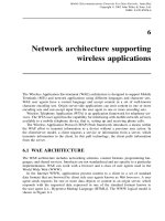
Figure 3.1 Division of radio resources in time and frequency domains to allow DPA for high
peak-rate data services.
The frame structures of adjacent Base Stations (BSs) are staggered in time; the neigh-
boring BSs sequentially perform the four different DPA functions with a predetermined
rotational schedule. This avoids collision of channel assignments. This protocol pro-
vides a basis for admission control and bit rate adaptation based on measured signal
quality.
Figure 3.1 shows radio resources allocation scheme in which 528 subchannels, each of
4.224 MHz, are organized into 22 clusters of 24 subchannels of 192 kHz each in frequency
and 8 time slots of 13 OFDM blocks each within a 20 ms frame of 128 blocks. This allows
flexibility in channel assignment while providing 24 blocks of control overhead to perform
the DPA procedures. Each tone cluster contains 22 individual modulation tones plus two
guard tones. There are 13 OFDM blocks in each traffic slot and two blocks are used
as overhead – a leading block for synchronization and a trailing block as guard time for
separating consecutive time slots. A radio resource is associated with a frequency hopping
pattern in which the packets are transmitted using eight different tone clusters in each of
the eight traffic slots. Coding across eight traffic slots for user data exploits frequency
diversity, which gives sufficient coding gain for performance enhancement in the fading
channel. This arrangement supports 22 resources in frequency that can be assigned by
DPA. Considering overhead for OFDM block guard time, synchronization, slot separation,
and DPA control, a peak data rate of 2.1296 (3. 3792 × 22/24 × 11/13 × 104/128) Mb s
−1
is available for packet data services using all 22 radio resources, each of 96.8 kb s
−1
.
Frame structure is shown in Figure 3.2 for downlink DPA. The uplink structure is sim-
ilar but the control functions are slightly different. In each frame the control channels for
both the uplink and downlink jointly perform the four DPA procedures sequentially with
a predetermined staggered schedule among adjacent BSs. The control c hannel overhead is
included to allow three sectors to perform DPA at different time periods. This allows inter-
ference reduction and additional Signal to Interference Ratio (SIR) enhancement for the
control information. Spectrum reuse is achieved for traffic channels through interference
avoidance using DPA to avoid slots causing potential interference. The frame structure
WIDEBAND WIRELESS LOCAL ACCESS 39
0.625 ms1.5625 ms1.5625 ms
10 OFDM
blocks
10 OFDM
blocks
BS 2 broadcasts
paging information
BS 1
transmits
a list of
assigned
channels/ACK
BS 1, 3, 4
transmit
pilots
Traffic slots
BS 1, 2, 3 and 4
transmit based
on DPA
1. BS 4
transmits
a list of
assigned
channels/ACK
2. BS 1 broadcasts
paging information
3. BS 2, 3, 4
transmit
pilots
3 blocks 3 blocks 3 blocks 3 blocks 3 blocks 3 blocks 3 blocks1 B 1 B
GuardGuardGuard Sector #3Sector #2Sector #1Sector #3Sector #2Sector #1
1 B
1 B 2 B
Sync
2 B
Sync
Pilots
1 B
4 OFDM
blocks
12
Frame
20 ms
Control slots 22 resources in 8 traffic slots Control slots
341234
Unused
channel
Superframe
80 ms
Superframe
80 ms
Figure 3.2 Frame structure for downlink DPA.
permits SIR e stimation on all unused traffic slots. The desired signal is estimated by the
received signal strength from the two OFDM blocks used for paging. The interference
is estimated by measuring three blocks of received pilot signals. The pilot channels are
generated by mapping all the radio resources currently in use onto corresponding pilot
subchannels, thus providing an interference map without monitoring the actual traffic
subchannels. The OFDM scheme handles many subchannels in parallel, which allows
for fast SIR estimation. The measurement errors are reduced through significant diversity
effects with 528 available subchannels to map 22 resources over three OFDM blocks.
The estimated SIR is compared against an admission threshold (for instance, 10 dB), and
channel occupancy can be controlled to achieve good Quality of Service ( QoS) for the
admitted users.
3.2.2 Wireless services support in local multipoint distribution systems
Several systems support broadband wireless communications and mobile user access.
These are the Multichannel Multipoint Distribution System (MMDS) and the Local Mul-
tipoint Distribution System (LMDS), also called Local Multipoint Communication System
(LMCS) or Microwave Video Distribution System (MVDS).
The MMDS systems work at frequencies lower than 5 GHz in large coverage areas
with cell radius of up to 40 km. MMDS systems can be used for transmission of video
40 WIRELESS LOCAL AREA NETWORKS
and broadcast services in rural areas. Because of the large cell size, MMDS systems do
not perform well for bidirectional communication that integrates a return channel.
The LMDS systems work with higher frequencies where a larger frequency spectrum
is available than that in the MMDS systems. The coverage for LMDS systems involves
smaller cells of up to 5 km radius and requires repeaters to be placed in a Line Of Sight
(LOS) configuration. This local coverage with a large available bandwidth makes LMDS
systems suitable for interactive multimedia services distribution.
Broadband wireless access is based on the Two-Layer Network (TLN) concept in
which subscribers are grouped into microcells, which are embedded into a macrocell.
The microcells coverage uses local repeaters operating at 5.8 GHz fed by a BS through
40 GHz links. OFDM modulation is used to allow the reception with plug-free receivers
located inside the buildings. A 40 GHz band fixed receiver provides a rooftop antenna in
LOS with the transmitting antenna. This LMDS system provides a n integrated wireless
return channel.
The LMDS architecture uses co-sited BS equipment. The indoor digital equipment
connects to the network infrastructure, and the outdoor microwave equipment mounted
on the rooftop is housed at the same location. The Radio Frequency (RF) planning uses
multiple sector microwave systems, where the cell site coverage is divided into 4, 8, 12,
16, or 24 sectors.
The user accesses the network through Hybrid Fiber Radio (HFR), Radio To The
Building (RTTB) and Radio To The Curb (RTTC). In HFR, a Radio Frequency Unit (RFU)
carries out signal down conversion from RF frequency to the intermediate frequency.
The signal feeds the Radio Termination (RT) of each user through a bus link. In RTTB
architecture the signal feeds the user Network Termination (NT) through point-to-point
cable links. In RTTC the RFU is placed in a common outdoor unit and is shared among
several buildings.
In high-population cities, LMDS systems can be used as LOS propagation channels at
high frequencies. LOS operation is inherently inflexible even for low mobility services.
On the other hand, the available bandwidth for LMDS frequencies exceeds 1 GHz, making
it a very desirable transmission method. The frequency bands assigned to MMDS and
LMDS are included in the frequency bands allocated for fixed services. The exception
is the 40.5–42.5-GHz band allocated for MVDS systems. The 28-GHz channel is not
generally open in several countries. This is why the 40-GHz technology is considered.
However, the baseband system is designed to be compatible with interchangeable RF
system (5/17/28/40 GHz).
LMDS is a stand-alone system providing wireless multimedia and Internet services,
and it can be used as the support infrastructure for other wireless multimedia services, for
example, UMTS, wireless LAN, and Broadband Radio Access Network (BRAN), which
provide a high-speed digital connection to the user.
Sukuvaara et al. proposed a two-layer 40-GHz LMDS system providing wireless inter-
active cellular television and multimedia network. The first layer, a macrocell, uses
40-GHz wireless connection between the BS and the sub–base station, which can be
a frequency and/or protocol conversion point called a local repeater. The second layer,
a microcell, operates at 5.8 GHz. The user can connect a multimedia PC (Personal Com-
puter) to a local repeater access point at 5.8 GHz or directly to the BS at 40 GHz. The
WIDEBAND WIRELESS LOCAL ACCESS 41
5.8 GHz connection can be used cost effectively within cities and high-density population
areas, and the 40 GHz connection can be used in rural areas. The macrocell size can be up
to 5 km. The microcell size is from 50 to 500 meters depending on services and location.
A 40-GHz transceiver unit serves dozens of microcell users. The microcell architecture
prevents LOS indoor propagation, supports nomadic terminals, and is cost effective.
3.2.3 Media Access Control (MAC) protocols for wideband wireless local access
Wireless LANs provide wideband wireless local access and offer intercommunication
capabilities to mobile applications. This technology is supported by 802.11 standard
developed by the IEEE 802 LAN standards organization. Wireless LANs are also pro-
vided by High Performance Radio LAN (HIPERLAN) Type 1 defined by the European
Telecommunications Standards I nstitute (ETSI) RES-10 Group.
IEEE 802.11 uses data rates up to 11 Mb s
−1
and defines two network topologies. The
infrastructure-based topology allows Mobile Terminals (MTs) to communicate with the
backbone network through an access point. In ad hoc topology, MTs communicate with
each other without connectivity to the wired backbone network. HIPERLAN uses data
rate 23.5 Mb s
−1
and the ad hoc topology.
QoS guarantees are achieved through infrastructure topology, and a priority scheme in
the Point Coordination Function (PCF) in the IEEE 802.11. HIPERLAN defines a channel
access priority scheme based on the lifetime of packets to achieve QoS.
Wireless Asynchronous Transfer Mode (WATM) standardization involves Wireless
ATM Group (WAG) of the ATM Forum and the BRAN project of ETSI. These efforts
involve developing a technology for wideband wireless local access that includes ATM
features in the radio interface, thus combining support of user mobility with statistical
multiplexing and QoS guarantee provided by wired ATM networks. The goal is to reduce
complexity of interworking between the wireless access network and the wired ATM
backbone and to attain a higher level of integration.
3.2.4 IEEE 802.11
The IEEE 802.11 MAC (Media Access Control) protocol provides asynchronous and
synchronous (contention-free) services, which are provided on top of physical layers and
for different data rates. The asynchronous service is mandatory, and the synchronous
service is optional.
The asynchronous service is provided by the Distributed Coordination Function (DCF),
which implements the basic access method of the IEEE 802.11 MAC protocol also known
as Carrier Sense Multiple Access with Collision Avoidance (CSMA/CA) protocol. The
implementation of DCF is mandatory.
Contention-free service is provided by the PCF, which implements a polling access
method. A point coordinator cyclically polls wireless stations, allowing them to transmit.
The PCF relies on the asynchronous service provided by the DCF. The implementation
of the PCF is not mandatory.
Basic access mechanism illustrated in Figure 3.3 explains that in DCF a station must
sense the medium before initiating transmission of a packet. If the medium is sensed to
42 WIRELESS LOCAL AREA NETWORKS
Packet arrival
Frame transmission
Elapsed backoff time
Residual backoff time
Frame
Frame
Frame
Frame
Station 1
Station 2
Station 3
Station 4
Station 5
DIFS DIFS DIFS DIFS
Frame
Figure 3.3 Basic access mechanism.
be idle for a time interval greater than a Distributed Interframe Space (DIFS), the station
transmits the packet. Otherwise, the transmission is deferred and the backoff process is
started. The station computes a random time interval, the backoff interval, uniformly
distributed between zero and a maximum called the Contention Window (CW). This
backoff interval is then used to initiate the backoff timer, which is decremented only
when the medium is idle, and it is frozen when another station is transmitting. Every time
the medium becomes idle, the station waits for a DIFS and then periodically decrements
the backoff timer. The decrementing period is the slot time corresponding to the maximum
round trip delay between two stations controlled by the same access point.
When the backoff timer expires, the station can access the medium. If more than one
station starts transmission simultaneously, a collision occurs. In a wireless environment,
collision detection is not possible. A positive acknowledgement ACK shown in Figure 3.4
is used to notify the sending station that the transmitted frame was successfully received.
The transmission of the ACK is initiated at a time interval equal to the Short Interframe
Space (SIFS) after the end of reception of the previous frame. The SIFS is shorter than
DIFS; thus the receiving station does not need to sense the medium before transmitting
the ACK.
If the ACK is not received, the station assumes that the transmitted frame was not
successfully received, and it schedules a retransmission and enters the backoff process
Frame
ACK
SIFS
Source station
Destination station
Figure 3.4 Acknowledgement mechanism.
WIDEBAND WIRELESS LOCAL ACCESS 43
again. After each unsuccessful transmission attempt, the CW is doubled until a predefined
maximum (CW
max
) is reached. This reduces the probability of collisions. After a successful
or unsuccessful frame transmission, the station must execute a new backoff process if there
are frames queued for transmission.
The hidden station problem occurs when a station successfully receives frames from
two different stations that cannot receive signals from each other. This may cause a station
to sense the medium being idle even if the other station is transmitting. This results in a
collision at the receiving station. The IEEE 802.11 MAC protocol includes an optional
mechanism based on the exchange of two short control frames, as shown in Figure 3.5, to
solve the hidden station problem. A Request To Send (RTS) frame is sent by a potential
transmitter to the receiver. A Clear To Send (CTS) frame is sent by the receiver in
response to the received RTS frame. If the CTS frame is not received within a predefined
time interval, the RTS frame is retransmitted by executing the backoff algorithm. After
a successful exchange of RTS and CTS frames, the data frame is sent by the transmitter
after waiting for a SIFS.
A duration field in RTS and CTS frames specifies the time interval necessary to com-
pletely transmit the data frame and the related ACK. This information is used by the
stations that hear either the transmitter or the receiver to update their Net Allocation
Vector (NAV), a timer that is continuously decremented regardless of the status of the
medium. The stations that hear either the transmitter or the receiver refrain from trans-
mitting until their NAV expires, and the probability of a collision occurring because of
a hidden station is reduced. The RTS/CTS mechanism introduces an overhead that may
be significant for short data frames. When RTS/CTS mechanism is enabled, collisions
can occur only during the transmission of the RTS frame, which is shorter than the data
frame. This reduces the time of collision and wasted bandwidth.
The effectiveness of the RTS/CTS mechanism depends on the length of the data frame
to be protected. The RTS/CTS mechanism improves the performance when data frame
sizes are larger than the size of the RTS frame, which is the RTS threshold. The RTS/CTS
mechanism is enabled for data frame sizes over the threshold and is disabled for data frame
sizes under the threshold.
To support time-bounded services the IEEE 802.11 standard defines the PCF to allow
a single station in each cell to have a priority access to the medium. This is implemented
by using the PCF Interframe Space (PIFS) and a beacon frame that notifies all the other
RTS
Source station (3)
Destination station (2)
Stations close to the source (4)
Stations close to destination (1)
CTS
NAV
NAV
SIFS SIFS SIFS
ACK
Frame
Figure 3.5 Request To Send/Clear To Send (RTS/CTS) mechanism.
44 WIRELESS LOCAL AREA NETWORKS
stations in the cell not to initiate transmissions for the length of the Contention-Free
Period (CFP). When all the stations are silenced, the PCF station allows a given station to
have contention-free access by using an optional polling frame sent by the PCF station.
The length of the CFP can vary within each CFP repetition interval, depending on the
system load.
3.2.5 ETSI HIPERLAN
HIPERLAN standards defined by ETSI are high performance radio LANs. There are four
HIPERLAN types illustrated in Figure 3.6 with the operating frequencies and indicative
data transfer rates on the radio interface.
In HIPERLAN Type 1, which is also Wireless 8802 LAN, the HIPERLAN Chan-
nel Access Mechanism (CAM) is based on channel sensing and a contention resolution
scheme called Elimination Yield – Non-preemptive Priority Multiple Access (EY-NPMA).
The channel status is sensed by each station in the network. If the channel is sensed as
being idle for at least 1700 bit periods, the channel is considered free, and the station is
allowed to start transmission of the data frame. Each data frame transmission must be
acknowledged by an ACK from the destination station.
If the channel is not free when a frame transmission is desired, a channel access with
synchronization takes place. Synchronization is performed at the end of the previous
transmission interval, and the channel access cycle begins according to the EY-NPMA
scheme. The channel access cycle consists of three phases: prioritization, contention, and
transmission. Figure 3.7 shows an example of a channel access cycle with synchronization.
Prioritization phase is used to allow only contending stations with the highest priority
frames to participate in the next phase. A CAM priority level h is assigned to each frame.
Priority levels are numbered from 0 to (H − 1), where 0 is the highest priority level. The
prioritization phase consists of at most H prioritization slots, each 256 bit periods long.
During priority detection, each station that has a frame with CAM priority level h senses
the channel f or the first h prioritization slots. In priority assertion, if the channel is idle
during this interval, the station transmits a burst in the (h + 1)th slot, and it is admitted
to the contention phase. Otherwise, it stops contending and waits for the channel access
cycle. The contention phase starts immediately after transmission prioritization burst and
consists of two further phases – elimination and yield.
HIPERLAN
Type 4
Wireless ATM
interconnect
DLC
PHY
(17 GHz)
(155 Mb s
−1
)
HIPERLAN
Type 3
Wireless ATM
remote access
DLC
PHY
(5 GHz)
(20 Mb s
−1
)
HIPERLAN
Type 2
Wireless ATM
short-range
access
DLC
PHY
(5 GHz)
(20 Mb s
−1
)
HIPERLAN
Type 1
Wireless 8802
LAN
MAC
PHY
(5 GHz)
(23 Mb s
−1
)
Figure 3.6 HIPERLAN types.
WIDEBAND WIRELESS LOCAL ACCESS 45
Prioritization
phase
Priority
detection
Priority
assertion
Cycle
syncronization
interval
Contention
phase
Transmission
phase
Data frame
Yield
phase
DB
Survival
verification
interval
Elimination
phase
ACK
Figure 3.7 Channel access cycle with synchronization.
46 WIRELESS LOCAL AREA NETWORKS
The elimination phase consists of at most n elimination slots, each 256 bit periods
long, followed by a 256–bit period–long elimination survival verification slot. Beginning
with the first elimination slot, each station transmits a burst for a number B of elimination
slots, according to the following truncated geometric probability distribution function:
Pr{B = b}=
(1 − q)q
b
0 ≤ b<n
q
n
b = n
When burst transmission ends, each station senses the channel for the duration of the
elimination survival verification slot. If the channel is sensed as being idle, the sta-
tion is admitted to the yield phase. Otherwise, the station drops itself from contention
and waits for the next channel access cycle. The yield phase starts after the end of
the elimination survival verification interval and consists of at most m yield slots, each
64–bit periods–long. Each station listens to the channel for a number D of yield slots
before beginning transmission, if allowed. Variable D has a truncated geometric distribu-
tion function:
Pr{D = d}=
(1 − p)p
d
0 ≤ d<m
p
m
d = m
If the channel is sensed idle during the yield listening interval, the station is allowed to
begin the transmission phase. Otherwise, the station looses contention and waits for the
next channel access cycle.
The elimination and yield phases are complementary. The elimination phase reduces
the number N of stations taking part in the channel access cycle. The yield phase, which
performs well w ith the small number of contending stations, further reduces the number
of stations allowed to transmit, possibly even to one. Furthermore, with EY-NPMA at
least one station is always allowed to transmit.
Real-time traffic transmission is supported by dynamically varying the CAM priority
depending on the user priority and packet residual lifetime. The user priority is assigned
to each packet according to the type of traffic it carries; it determines the maximum CAM
priority value the packet can reach. The residual packet lifetime is the time interval in
which the transmission of the packet must occur before the packet must be discarded. Since
multihop routing is supported by the standard, the residual packet lifetime is normalized
to the number of hops the packet has to traverse to reach the final destination.
HIPERLAN Type 2 is a short-range wireless access to ATM networks providing local
wireless access to ATM infrastructure networks by terminals that interact with access
points connected to an ATM switch or multiplexer. WATM access network provides
the QoS, including the required data transfer rates the users expect from a wired ATM
network. The specification of HIPERLAN Type 2 is carried out by ETSI BRAN.
3.2.6 Dynamic slot assignment
Dynamic Slot Assignment (DSA++) protocol extends the ATM statistical multiplexing to
the radio interface of wireless users. The architecture of ATM multiplexer with radio cell
is shown in Figure 3.8. The radio cell has a central BS and Wireless Terminals (WTs),
WIDEBAND WIRELESS LOCAL ACCESS 47
Physical
layer
Physical
layer
AT M
AT M
M-LLC
M-MAC
M-PHY
Physical
layer
AT M
M-LLC
M-MAC
M-PHY
Physical
layer
AT M
M-LLC
M-MAC
M-PHY
M-LLC
M-MAC
M-PHY
User services
User services
User services
Wireless ATM terminal
Base station
Physical
layer
AT M
AAL
Physical
layer
Physical
layer
Physical
layer
Physical
layer
Physical
layer
AT M
ATM multiplexer
AT M
AAL
Physical
layer
AT M
AAL
User services
Physical
layer
AT M
AAL
User services
Physical
layer
AT M
AAL
User services
ATM terminal
Physical
layer
AT M
AAL
Figure 3.8 Architecture of ATM multiplexer with radio cell.
48 WIRELESS LOCAL AREA NETWORKS
and can be viewed as a distributed, virtual ATM multiplexer with a radio interface inside.
This allows for a centralized master–slave type of MAC protocol, where the BS, as the
master of a r adio cell, schedules the contention-free transmission of ATM cells on the
uplink and downlink.
The virtual ATM multiplexer represents a distributed queuing system with queues
inside the WTs for uplink cells and the BS for downlink cells. Similarly, as in fixed
ATM networks with a relatively low data rate (e.g., 20 MB s
−1
), the QoS requirements of
real-time oriented services can only be supported if the transmission order of ATM cells
is based on the waiting time inside the queues. The BS needs to have current knowledge
of the capacity requirements of the mobile WTs. This can be achieved by piggybacking
onto uplink ATM cells the instantaneous requirements of each mobile WT. However, it
may not be possible to piggyback the newest requirements, that is, the mobile WT is
idle. In this case, WTs are provided with special uplink signaling slots so that they can
transmit their capacity requests to the BS according to a random access scheme.
The DSA++ protocol is implemented on top of a Time Division Multiple Access
(TDMA) channel. Time slots may carry either a signaling burst or one ATM cell along
with the a dditional signaling overhead of the physical layer. A Time Division Duplex
(TDD) system is implemented to build up the uplink and downlink channels.
Time slots are grouped together into signaling periods. Figure 3.9 shows a frame struc-
ture of a signaling period. The length of each signaling period, and the ratio between the
uplink and downlink sections, is variable and assigned dynamically by the BS to cope
with the c urrent load of the system. Each signaling period consists of four phases.
Downlink signaling: The downlink signaling burst is transmitted from the BS to the WTs
and opens a signaling period of a specific length, giving information about the structure
and slot assignments of the signaling period. The downlink signaling informs the WTs
about the number of slots in the other three phases and contains at least
• a reservation message for each uplink slot of the signaling period;
Signaling periodSignaling periodSignaling period
Downlink Cells
Uplink Cells
Uplink Signaling
Downlink Signaling
Time
Transceiver
turnaround
interval
Figure 3.9 Frame structure of a signaling period.
WIDEBAND WIRELESS LOCAL ACCESS 49
• an announcement message for each downlink slot of the signaling period;
• a control message to implement the collision resolution algorithm of the random access.
Downlink cells: In this phase the downlink cells are transmitted contention-free from the
BS to the WTs.
Uplink cells: Since each of these slots is assigned to specific WTs, in this phase uplink
cells are transmitted contention-free from the WTs to the BS.
Uplink signaling: During this phase, which is carried out via a sequence of short slots,
the WTs have the possibility to access the channel to signal their capacity requests to
the BS.
Random access is used for transmission of the capacity requests of the WTs. To guaran-
tee the QoS requirements of the connections, f ast collision resolution with a deterministic
delay is essential. Since all WTs are the possible candidates to transmit via random access
and are known by the BS, an identifier splitting algorithm can be used, which leads to
short and deterministic delays to resolve any collision. The splitting algorithm groups
the terminals into sets. All terminals in a setareallowedtotransmitinaspecificslot.A
transmission will only be successful if exactly one terminal in a set transmits. If a collision
occurs, the set is divided into subsets according to the order of the splitting algorithm.
In the case of an identifier splitting algorithm, the follow-up subset is determined by the
identifier of the terminal. An example of a binary identifier splitting algorithm with an
identifier space of dimension n = 4 is shown in Figure 3.10, where τ
p
is the duration of
a period able to offer any random access slots.
In DSA++ protocol, at the beginning of each frame the identifier space of size N
is divided into a variable number t of consecutive intervals and a random access slot
nn
− 1
n
+ 1
t
[t
P
]
Identifier
space
5 terminals selected
randomly
First digit is 1First digit is 0
0000
0001
000
00
1
0
1
1
00
11
01
11
100
001
011
011
0011
1000
1100
1011
1000
0001 1001
0010 1010
0011 1011
0100 1100
0101 1101
0110 1110
0111 1111
Figure 3.10 An example of a binary identifier splitting algorithm.
50 WIRELESS LOCAL AREA NETWORKS
is assigned to each interval. The l th interval starts with terminal i
l
and ends with ter-
minal (i
{l+1}
− 1), with i
1
= 0, and i
t
= (N − 1). The downlink signaling burst signals
the interval division to the WTs by transmitting the start identifier i
l
of each interval.
The maximum time required to resolve the collision is limited because of the limited and
known number of WTs served by the BS. Petras and Kramling show that the solution
time of a collision can be reduced by using an estimate of the transmission probability of
each terminal to determine the size of the subsets and the splitting order.
The coding of the capacity requests and the scheduling algorithm depend on the ATM-
service class. An earliest due date strategy is used for Constant Bit Rate (CBR) and
real-time Variable Bit Rate (rt-VBR) service classes. For Available Bit Rate (ABR) and
Unspecified Bit Rate (UBR) service classes, Fair Weighted Queuing and First Come First
Served (FCFS) strategies are used.
3.3 SUMMARY
In IPv6, a special address range is reserved for multicast addresses for each scope, and
a multicast is only received by the hosts in this scope, which are configured to listen to
this specific multicast address. To address all hosts in a certain scope with a multicast,
the multicast must be made to the predefined all-nodes address, to which all hosts must
listen. When existing software using IPv4 is migrated to IPv6, the IPv4 broadcasts are
changed to multicasts to the all-nodes address, as this is the simplest way to maintain the
complete functionality of the software.
In a workgroup address configuration, the host sends a DHCP Request with a Work-
group Address Extension to the DHCP Server. The DHCP Server replies with a Workgroup
Address Extension containing all workgroup addresses assigned to this host. After receiv-
ing the workgroup addresses, the host sends ICMPv6 Group Membership Report to each
of its workgroup addresses to inform the multicast routers about its new membership in
these multicast groups.
OFDM modulation combined with DPA with wideband 5-MHz channels for high-speed
packet data wireless access in macrocellular and microcellular environments supports bit
rates ranging from 2 to 10 Mb s
−1
. OFDM can largely eliminate the effects of intersymbol
interference for high-speed transmission rates in very dispersive environments. OFDM
supports interference suppression and space–time coding to enhance efficiency. DPA
supports spectrum efficiency and high-rate data access.
Several systems support broadband wireless communications and mobile user access.
These are MMDS and LMDS, also called LMCS or MVDS.
Broadband wireless access is based on the TLN concept in which subscribers are
grouped into microcells, which are embedded into a macrocell. The microcells coverage
uses local repeaters operating at 5.8 GHz fed by a BS through 40-GHz links. OFDM
modulation is used to allow the reception with plug-free receivers located inside the
buildings. A 40-GHz band fixed receiver provides a rooftop antenna in LOS with the
transmitting antenna. This LMDS system provides an integrated wireless return channel.
IEEE 802.11 uses data rates up to 2 Mb s
−1
and defines two network topologies. The
infrastructure-based topology allows MTs to communicate with the backbone network
PROBLEMS TO CHAPTER 3 51
through an access point. In ad hoc topology, MTs communicate with each other without
connectivity to the wired backbone network. HIPERLAN uses data rate 23.5 Mb s
−1
and
the ad hoc topology.
DSA++ protocol extends the ATM statistical multiplexing to the radio interface of
wireless users. The architecture of ATM multiplexer with radio cell has a central BS and
WTs, and can be viewed as a distributed, virtual ATM multiplexer with a radio interface
inside. This allows for a centralized master-slave type of MAC protocol, in which the BS,
as the master of a radio cell, schedules the contention-free transmission of ATM cells on
the uplink and downlink.
PROBLEMS TO CHAPTER 3
Wireless local area networks
Learning objectives
After completing this chapter, you are able to
• demonstrate an understanding of virtual LANs;
• explain the role of workgroups;
• explain multicasting in virtual LANs;
• explain workgroup address configuration;
• demonstrate an understanding of OFDM;
• explain what WCDMA is;
• explain DPA;
• demonstrate an understanding of LMDS;
• explain what MMDS is;
• explain what HFR, RTTB, and RTTC are;
• demonstrate an understanding of different MAC protocols for wideband wireless local
access;
• explain what IEEE 802.11 and HIPERLAN standards are;
• explain what Dynamic Slot Assignment (DSA++)protocolis;
Practice problems
3.1: What are the workgroups?
3.2: How is multicasting done in IPv6?
3.3: How is administration of workgroups designed?
3.4: What peak bit rates are supported by OFDM?
3.5: What is the role of WCDMA?
3.6: What is the function of DPA?
3.7: What is the role of BRAN?
3.8: What can the MMDS systems be used for?
3.9: What is the coverage for LMDS systems?
3.10: How does the user access the network?
52 WIRELESS LOCAL AREA NETWORKS
3.11: What are the services provided by the IEEE 802.11 MAC?
3.12: How does the CAM work in HIPERLAN Type 1?
3.13: How does the DSA++ protocol extend the ATM statistical multiplexing?
Practice problem solutions
3.1: The workgroups are groups of hosts sharing the same servers and other resources
over the network. The hosts of a workgroup are attached to the same LAN segment,
and broadcasting can be used for server detection, name resolution, and name
reservation.
3.2: In IPv6, a special address range is reserved for multicast addresses for each scope,
and a multicast is only received by the hosts in this scope, which are configured
to listen to this specific multicast address. To address all hosts in a certain scope
with a multicast, the multicast must be made to the predefined all-nodes address,
to which all hosts must listen. When existing software using IPv4 is migrated to
IPv6, the I Pv4 broadcasts are changed to multicasts to the all-nodes address, as this
is the simplest way to maintain the complete functionality of the software.
IPv6 multicasting can be used to form the broadcast scope of a workgroup. The
workgroup is the multicast group, whose hosts listen to the same multicast address,
the w orkgroup address. A host can listen to several multicast addresses at the same
time and can be a member of several workgroups.
Multicasting exists optionally for IPv4 and is limited by a maximum of hops.
The multicast in IPv6 is limited by its scope, which is the address range.
3.3: The administration of the workgroups is designed by storing the information about
hosts and their workgroups in a central database in a DHCP server. The information
is distributed by using the DHCPv6.
3.4: OFDM modulation combined with DPA with wideband 5-MHz channels for high-
speed packet data wireless access in macrocellular and microcellular environments,
supports peak bit rates ranging from 2 to 10 Mb s
−1
.
3.5: WCDMA uses 5-MHz channels and supports circuit and packet data access at
384 kb s
−1
nominal data rates for macrocellular wireless access. WCDMA provides
simultaneous voice and data services.
3.6: DPA is based on properties of an OFDM physical layer. DPA reassigns transmission
resources on a packet-by-packet basis using high-speed receiver measurements.
3.7: BRAN provides a high-speed digital connection to the user.
3.8: The MMDS systems work at frequencies lower than 5 GHz in large coverage areas
with cell radius of up to 40 km. MMDS systems can be used for transmission of
video and broadcast services in rural areas. Because of a large cell size, MMDS
systems do not perform well for bidirectional communication that integrates a
return channel.
3.9: The LMDS systems work with higher frequencies where larger frequency spectrum
is available than that in the MMDS systems. The coverage for LMDS systems
involves smaller cells of up to 5-km radius, and requires repeaters to be placed in
a LOS configuration. This local coverage with a large available bandwidth makes
LMDS systems suitable for interactive multimedia services distribution.
PROBLEMS TO CHAPTER 3 53
3.10: The user accesses the network through HFR, RTTB, and RTTC. In HFR an RFU car-
ries out signal down conversion from RF frequency to the intermediate frequency.
The signal feeds the RT of each user through a bus link. In RTTB architecture the
signal feeds the user NT through point-to-point cable links. In RTTC the RFU is
placed in a common outdoor unit and is shared among several buildings.
3.11: The IEEE 802.11 MAC (Media Access Control) protocol provides asynchronous
and synchronous (contention-free) services, which are provided on top of physical
layers and for different data rates. The asynchronous service is mandatory, and the
synchronous service is optional.
3.12: In HIPERLAN Type 1, which is also a Wireless 8802 LAN, the HIPERLAN CAM
is based on channel sensing and a contention resolution scheme called EY-NPMA.
The channel status is sensed by each station in the network. If the channel is
sensed as being idle for at least 1700 bit periods, the channel is considered free,
and the station is allowed to start transmission of the data frame. Each data frame
transmission must be acknowledged by an ACK from the destination station.
If the channel is not free when a frame transmission is desired, a channel access
with synchronization takes place. Synchronization is performed at the end of the
previous transmission interval, and the channel access cycle begins according to
the EY-NPMA scheme. The channel access cycle consists of three phases: priori-
tization, contention, and transmission.
3.13: DSA++ protocol extends the ATM statistical multiplexing to the radio interface of
wireless users. The architecture of ATM multiplexer with radio cell has a central
BS and WTs and can be viewed as a distributed, virtual ATM multiplexer with
a radio interface inside. This allows for a centralized master-slave type of MAC
protocol, in which the BS, as the master of a radio cell, schedules the contention-free
transmission of ATM cells on the uplink and downlink.